Le Shuttle, the locomotive from Eurotunnel
Gabriel MOISA
Technical University Cluj-Napoca
Abstract
This paper present some performances of locomotive ‘Le Shuttle’, so-called locomotive from ‘Eurotunnel’, techniques characteristics of traction motors 6 FHA 7079 and converters witch use it, the principal electric scheme and its function principle and no at last rind the principle scheme of command-control equipment MICAS-S2 with detailed description of its operation mode.
Keywords
Locomotive characteristics, Command systems, Control systems, European railways.
1. Introduction
“Euroshuttle Consortium Locomotives” put in traffic in year 1994 on the summer 38 locomotives from this series intended to support the different performances: for obtain exceptional traction effort, bred power and a optimum load axle, a weak wearing out on the wheels, but by a maximal availability, was chosen the formula with three bogie at two axle, provided with proper converter.
The progress realized in the fabrication of thyristors GTO and command-control techniques assisted by microcomputer was resented since of construction on the first polyvalent locomotives Re 456. The command system MICAS–S2 based on logic, anterior was used on the high-speed locomotives ‘Loc. 2000’.
Excepting of their predecessors, the principal transformer was conceived in a particular manner by compact type.
Locomotives from this series, answers on extreme severe exigency: safety in case of wrecks, rigorous observance of timetable, redundancy, optimum traffic frequency, and big reliability.
2. Technical Description
In year 1994 on the summer, ”Euroshuttle Consortium Locomotives” put in traffic 38 locomotives from this series. Because of: slashing conditions of exploitation like: big towed weight (coaches and car transportation trucks), air pressure exerted in the tunnel (Eurotunel), the locomotives had an axle disposition type Bo’Bo’Bo’, provided with a proper converter for each motor bogies. For “Le Shuttle” was realized a force circuit less sophisticated who used frequency static converters in three points circuits. The converters are purely with two interchangeable tension levels, with less of semiconductor elements.
The locomotive is powered by single-phase alternating current, with 25 kV tension and 50 Hz frequency. The maxim shaft power touch 5600 kW, the maxim torque 400 kN∙m and maxim voyage speed 160 km/h, in accord of air pumping and the tunnel ramps.
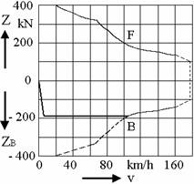
(F-Traction; B-Braking; v-Speed; Z-Active torque; ZB-Breaking torque)
Figure no 1. Torque-speed diagram of locomotive “Le Shuttle”
The traction motors have six poles, thick bares, isolation class H and forcible ventilation. The motors touch the maxim speed at 139 Hz and 2180 V like effective value. The nominal apparent power is 960 kW at 1100 rot/min. The electric energy was assumed from alternating current mains by two asymmetric pantographs, which were attached at a direction reverse situated under the principal vacuum circuit breaker, who supply the principal transformer.
Figure no 2. The principal electric scheme of locomotive
Legend:
1 – Pantograph; 2 – Pantographs section;
5 – Principal automatic circuit-breaker of vehicle (with vacuum) with interrupter for earthling;
7 – Principal transformer; 9 – Thunderrod;
11.0 –Traction frequency converter;
12/1,12/2 – Network single-phase converter 1 and 2;
12/3 – Three-phase inverter, 1 and 2 phases;
12.1 – Contactor for coupling the resistance from position 14;
12.2 – Section contactor;
13 – Three-phase inverter (3-nd phase) and instantaneous tension limiter;
14 – Resistance for striking current limit;
15.2 – Resistance of instantaneous tension limiter;
15.3 – The coil of smoothing circuit;
15.4 – The condenser of smoothing circuit;
15.5 – The condenser of intermediate circuit;
20 – Traction three-phase induction motor;
A –Frequency converter for auxiliary services;
C – Converter of train collector bar;
DG – Bogie.
The six secondary windings (identical) for motors supplying are galvanic separated. The motoring bogies are independent carrying away. Each of the two motors that compose a bogie was supplied by means of proper converter, which are commanded and coordinatessed by means of vehicle commander appliance, from the vehicle driven level.
Each system current converter of the three traction converters was supplied by means of single-phase rectifier at full wave by two separated windings of the transformer. By precise command of ignition angle and frequency modulation of the pulses was obtain a power factor between 0.98 inductive and 1. The current supplies converter the intermediate circuit by continuous tension situated between 2.4 and 2.8 kV, in accord of load torque. In case of an overvoltage (fault on a line), a GTO thyristor introduce in circuit a big power resistance. That particularity is important already in case of regenerative braking, when could be surpassed the maxim admit tension in intermediate circuit. The frequency modulation principle is applied until the flux weackage are beginning. Therefore, at big speed the GTO thyristors conduct at an appropriate half-wave. The thyristors bridges from power supply system and traction of the converter are specific to regulation in two points, which allow the optimum simulation of a sinusoidal wave. All the GTO function status is commanded by means of logical command appliance of the converters (SLG).
In cadre of MICAS-S2 system, the control and command functions are assured by means of computer, which command apparatus vehicle logic works (FLG). Accordingly, the different commands are direction to station bus compacted, where is controlled the retransmission messages reception too. If was selected, for example, a constant speeds, the instruction calculus the request torque and transmits the value to traction converters. The traction command apparatus (ALG) from different traction units determine arious parameters and ignition angles of GTO thyristors, necessary for elaboration of torque impose by FLG. At the same time, the ALG control the observance of exploitation conditions (temperature and currents) and take itself the protection functions that appertain on this level.
ALG and SLG logic is peeling faster than FLG logic. The two locomotives and wagons are interconnection by two data buses. This bus work beyond multiple transmissions by frequency shift principle. So that, the two locomotives can by commanded and diagnosed setting out since driven locomotive.
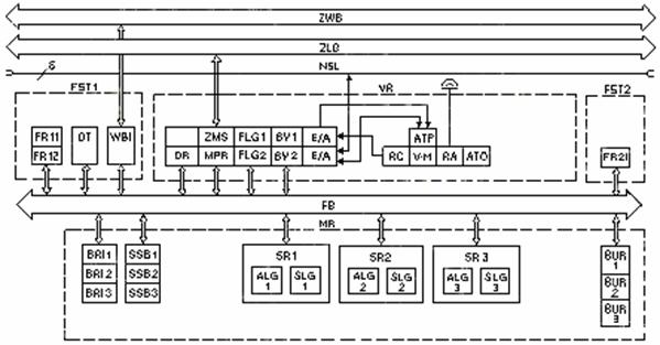
Figure no 3. The scheme by principle of command-control equipment
Legend:
ALG - traction command apparatus;
ATO - pace automaton command;
ATP - train automaton surveillance;
BRI - calculator-braking interface;
BUR - command apparatus of converter frequency supply;
BV - bus controller;
DR- diagnostic computer;
DT- diagnostic terminal;
E/A - input/output interface;
FB - vehicle bus;
FLG - vehicle command-control apparatus;
FR – computer of pilotage cabin;
FST- engine driver’s room;
MPR - Micas visualisation system;
MR - machine room;
NSL - multiple emergency command line (6 conductors);
RA - radio installation;
RC - radio command;
SLG - converter command apparatus;
SR - traction converter;
SSB - command currents block;
V-M - tachometric installation;
VR - vestibule room;
WBI - wagon bus interface;
ZLB - loc-loc bus;
ZMS - multiple commands on time multiplexer;
ZWB - wagon bus.
The connection loc-loc bus and wagon bus is established by means of traction automate coupling by pressure. The command modules are supplied at 110 V permanently, by locomotive battery. Before of switching, the system receive a test routine before than the inquiry sequence is beginning. The command and regulating parameters are sticking on the monitor in the driven cabin. The diagnostic functions are organised by three levels: the first level include locomotive leader’s message and instruction; the second level message and instruction settle the messages list memorised at overheads personnel’s intention and the last provide assistance for detailed tracking of troubles.
In ALG are integrated the antiskating and antisliding functions of different traction units. In centre of antisliding protection is finding a motor torque command, very sensible, with a reaction time of milliseconds order. If the system observes some axle packing, the torque is reduced la until 40 %, according to the sliding conditions, by means of tension high frequency chopping. The adaptive algorithms assure a correct behaviour in every exploitation conditions. The requested electric braking torque regulation is transmitted between the locomotives by means of loc-loc bus. The electric and pneumatic braking is combined. The command algorithms of skating status ASM supervise in order that was provided a balanced braking effect, less of current shocks.
3. Conclusions
Due to performances remembered in this paper and in the introductory part of work, is worth an thoroughgoing study by this locomotive in different situation: start, acceleration, pace, breakage, load, being therewith an interest in his implementation in our country Romania too, account of his working parameters: 25 kV/50 Hz on pantograph, identical with nationals parameters.
References
[1] Eggenberger, H.-P., Treacy, R.: Revue ABB 4/1994.
[2] Streiff, H.: La locomotive Bo’Bo’Bo’ serie 6/6 des Chemin de fer federaux suisses, Revue Brown Boveri, 64/1977.
[3] Balzarini, G., Haller, B.: Les nouvelles locomotives de ligne re 4/4 du Chemin de fer BT et du Chemin de fer SZU, Revue Brown Boveri, 74/1987.
[4] Eggenberger, H.: Locomotives a convertisseurs avec entrainement triphase pour Reseau Express Regional Zurich, Revue ABB, 10/90.
[5] Galliker, F.: Bauformen der ABB-Fahrmotoren fur alle kommenden Zugforderungsaufgaben, ABB Systemes de transport SA, Zurich, imprime CH-B 0940 D.