Loco2000. Technical Characteristics
Gabriel MOISA
Technical University Cluj-Napoca
Abstract
The paper show the function parameters of locomotive components “Loco 2000”, putting accent from their maximal values; the mode who works the force circuit, insisting of modulation technique necessary to obtain a high power factor and to eliminate harmonics. Is described the mode in who are realized the speed regulation and the afferent exploitation data. In the ultimate part of work is presenting the operation mode of the command-control MICAS-S2 system, the different commands imposed to others components (of the force circuit) and, in finale, the three diagnostic levels putting in service in case of troubles in system.
Keywords
Locomotive characteristics, Command systems, Control systems, European railways.
1. Introduction
“Loco 2000”, Re 4/4 460 type, is began in the trans-alpine transport in 1992 year, on the autumn. Is realized under ABB limited, Zurich and respond to very high exigencies, that: high traction force, necessary to surmount big ramps who reach occasionally 27 ‰, a good curve situate and small maintenance necessity. Is concept to generate minimal network troubles, to use fully the regenerative braking, who the denomination “exploitation less of wearing”. The locomotive use on the first the principal automatic circuit breaker with vide, developed by ABB, who no necessitate, practically, no maintenance. She uses frequently the regenerative braking, practically to stop, being a little fault of current on the supply under the route that circulates. Being given the entire exploitations exigency from European railways by 15 kV, 16 2/3 Hz, can be adapted on c.c. network by 3000 V, she can circulate very good in others countries than Switzerland.
2. Technical Description
The commercial exploitation of this type of locomotives is begun in year 1992 in the autumn. They are realized by “ABB Sistèmes de Transport SA” Zurich from cadre of Federal railroads (CFF). Them are in measure to circulate under ramps by 27‰, developing a maxim torque by 192 kN∙m. The maxim torque is available at a speed by 88 km/h, situated in proximity of adherence limit. At maxim technique speed, that is reducing under la 83 kN∙m. In her sequence, the axle power oscillates between 6100 and 4800 kW.
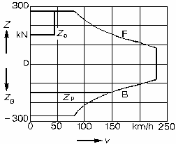
(F-Traction, B-Braking, v-Speed, Z-Axle torque,
ZB- Axle braking torque, Zp-Limit of adherence force)
Figure no 1. Torque-speed diagram of locomotive Re 4/4 460
The force electric circuit contents the principal transformer, with four independent traction windings, where are racordate, two by two, the frequency static converters. Hereby, in case of defect of a traction system, the train can continue the race at half-power.
The GTO thyristors, with a blockage tension by 4.5 kV and a commutation current by 2.5 kA, permit the exploitation of intermediate converter circuit, in coupling so called in three points, with a nominal tension by 3.5 kV. For high powers, is benefiting a high tension in the intermediate circuit and permit the mention of currents between the admissible limits. She offer, such as, the possibility to use some circuit for two-current locomotives, that circulate at continuum current network by 3000 V. Otherwise, is similar with locomotive ÖBB, series 1822. Grace of triple tension levels (0, 50 and 100%), the three points coupling of intermediate circuit offer the advantage of a bigger approximation of sinusoid. In this case, the request in tension of thyristors is not so big and is not need by a series coupling of semiconductor devices between poles.
The traction motors are high speeds, with four poles and the armature in court-circuit. The maxim speed is by 4180 rot/min, with a supply frequency by 143 Hz. The motors power in continuum regime is by 1200 kW, at a tension by 2640 V. The admissible overload is Pmax = 1560 kW. The isolation and leakage inductance are geared to the particular exploitation conditions with inverter, by manner that the supplementary inductance for attenuate of harmonics no be necessary.
The locomotive uses the regenerative braking as a prime priority. She serves to maintenance of train speed in descent under pant, as energy recuperation, practically to stop. Therefrom is the denomination “wearing out exploitation”. For protection anti over voltages of short duration, that can produce unexpected uncouples, in the intermediate circuit are integrated protection resistance. These resistance are coupling in case of network wedge, of system disturbs and their critics dynamic phenomenon.
The entrance converters (by four quadrants) as the three-phase inverter are constituted by commutations (valve clearances) identical. Each of the two entrance converters is formatted by four identical valve clearances, situated in the secondary of principal transformer. Is practised the synchronous modulation format by 12 network synchronous impulses. The entrance converter modifies the ratio active power-reactive power by variation of width and phase of impulse. The impulses from eight valve clearances are synchronous and shifting, the resulting impulses at frequency by 1600 Hz into primary of principal transformer. Therefore, the current by supply no contain than a harmonics spectre very diminishing. From network a power factor cosφ > 0.95, for powers higher than 50% from the nominal power is obtaining.
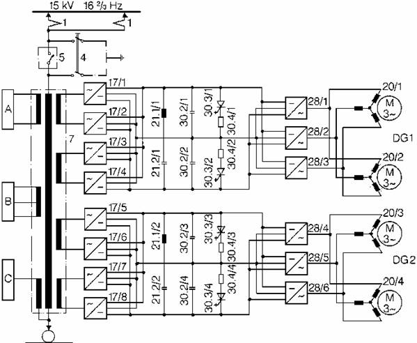
Figure no 2. The principal electric schema of locomotive Re 4/4 460
Legend for figure 2:
|
DG 1,2 - Bogie I and II (drive unit) A – Converter for auxiliary services B –The electric circuit of auxiliary services by 220 V C – Warming line by 1000 V 1 – Pantograph 4 – Earth connect circuit breaker 5 – Principal circuit breaker of vehicle (rapid with vacuum) 7 – Principal transformer |
|
17 – Single-phase converter (four quadrants) 20 – Traction three-phase asynchronous motor 21.1 – Filtration inductance 21.2 – Filtration condenser 28 – Three-phase inverter 30.2 – Condenser from intermediate circuit 30.3 – Instantaneous overvoltages limiter 30.4 – Afferent resistance |
Each of inverters is formed by three valve clearances, commanded with a postponement by 120 electric degrees. The frequency game is between 0 and 147 Hz and subdivision in three regulation games.
In start game, the rapport U/f is maintained constant. The total motor power is touched at 54 Hz (c.c.a. 1600 rot/min, respectively by 88 km/h). In medium game, to 125 Hz (c.c.a. 3650 rot/min, 200 km/h) all of motor maxim power is available.
In this case, the current must be decreasing, because of motors slide limit. The synchronisation of GTO thyristors it was chosen in so manner that the current harmonics into motors to be small of all the exploitation game. Therefore, the torque will be also small.
The central element of command-control MICAS-S2 system is the serial vehicle bus. Using conductors with optic fibres is possible a transmission speed by 1.1 Mb/sec and can, also, interconnect 256 apparatus address. This vehicle bus transmits the mechanic orders to vehicle command-control apparatus, which are treated and retransmission by bus to component apparatus. It was assuming the functions of “superior hierarchy”, that: pace speed regulation, calculation of traction and breakage effort values, the allotment between: electric braking, slippers braking and rail electromagnetic braking, effective speed treatment, as well as the surveillance of different limit values.
On the other hand, each of the two converter blocs contains the proper bus station, with concordant converter apparatus and the traction command-control.
The last is seeing about inverters command and surveillance function of converters. The apparatus receive the command values by means of the vehicle bus. In their sequence, they provide all along the time the effective status of converters to vehicle command-control apparatus.
The concordant information exchange is cyclic displaying, with different priorities. From redundancy motives, the important subsystems (bus control, pilot computer, central components) are two-ply, as the bus control.
The active control regulates the telegrams traffic, interrogating each bus station by a cyclic program, checking out simultaneous his functions.
The intern bus of each locomotive is interconnected with train bus by means of a bridge (alias two communication independent couplers). The signals of train bus are superimposed with command braking signals.
Legend
for figure 3: ALG - Traction
command-control apparatus BR - Braking computer BS - Bus station BUR - Converter for
auxiliary BV - Bus control DT - Diagnostic terminal DV - Diagnostics trait ELS - Electronic cupboard E/A - Entrance/exit SS - Interface StB - Electric command
cupboard UR- Converter unity FB - Vehicle bus FIS - Passengers
information system Fk – Radio FLG - Vehicle
command-control apparatus FR - Pilot room HB - Auxiliary services
block MPR - Diagram MICAS
computer MR - Machine room PT - Pneumatic keyboard SLG - Converters
command-control Apparatus v-M - Installation for
speed measurement ZB 1 -
Train bus 1 (EP line) Zb 2 - Train bus 2 (UIC
line) ZMS - Communication
coupling ZS - Security system ZUB - Train surveillance
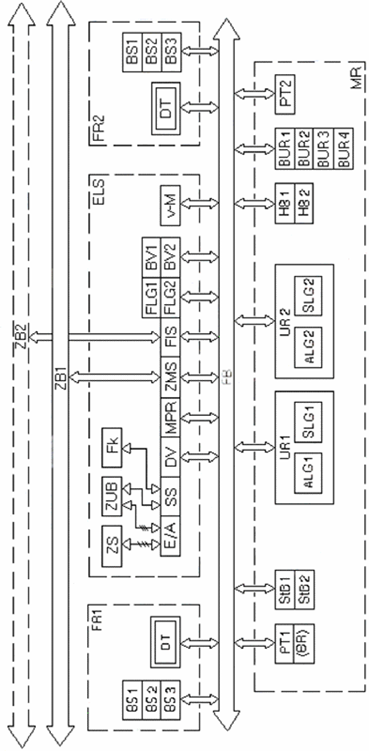
Figure no 3. The principle schema of command-control installation
All troubles signs and correspondent messages are pre-programmed in microcomputers decentralised of command-control level. These intimate the possible divergences by behaviour report imposed in their correspondent sector and transmit the information to trait diagnostics of the vehicle apparatus. Her memory, non-volatile, has a capacity by 2500 messages. The treatment of troubles of messages is making fewer than three levels.
In case of a non-correspondence, a lamp is switching on in front of mechanic. The short messages and the instructions are display on the screen, which is normally black.
By action of a debugger button, the mechanic can be ignored, set out of command desk and parts of installations very disturbed.
The second level is intended for little maintenance. Aid of simplified keyboard beside screen, can be interrogate the diagnostic trait apparatus, the registered trouble message appearing on the screen. The three level serves at deepen examination of troubles and the statistic trait of events.
All the data are load by portable PC sand transferred in a central data bank. In case of multiple commands, the different diagnostic systems form independent unity and the trouble messages are visualisation by means of train bus. As well as is, the visualisation the messages derived by coaches too.
3. Conclusions
Less of his performances, mention in this paper, is desirable that the power factor and the efficiency to be ameliorated. From this reason, is necessary a detailed study, theoretical and practical, in different situations: climbing and descent of ramps, the half-function (with a single supply bogie) and, why not, the regenerative braking tentative to stop (of train), earn to be surveyed.
References
[1] Jürg Lütscher, Paul Schläpfer – Loc 2000, Revue ABB 10/92.
[2] Gerber, M.; Drabek,E; Müller,R – Die Locomotiven 2000, Serie 460, der Schweizerischen Bundesbahnen, Schweizer Eisenbahn – Revue 10/1991.
[3] Weiss, T. – Die Lokomotive 2000 der Schweizerischen Bundesbahnen, 89 (1991) 11.
[4] Bonani, R. – Die elektrischen Locomotiven Re 4/4 der BT un der SZU mit Drehstrom Antriebstechnik.
[5] Kummrov, R.; Vitins, J. – Die Typefamilie “Lok 2000”. ZEV-Glasers Annalen 116 (1992) 9/10.
[6] Locomotives à convertisseur avec entraînement triphasé pour le Réseau Express Régional Zurich, Revue ABB 10/90.