Robust Controller Design for Speed Control of an Indirect Field Oriented Induction Machine Drive
A. MILOUDI*, A. DRAOU**
* University Centre of Saida, BP 138, En - Nasr, Saida 20000, Saida, Algeria
** University of Science and Technology of Oran, BP 1505 El M'naouar, Oran, Algeria
adraou@yahoo.com, amiloudidz@yahoo.fr
Abstract
The use of PI controllers for speed control of induction machine drives is characterized by an overshoot during tracking mode and a poor load disturbance rejection. This is mainly caused by the fact that the complexity of the system does not allow the gains of the PI controller to exceed a certain low value. At starting mode the high value of the error is amplified across the PI controller provoking high variations in the command torque. If the gains of the controller exceed a certain value, the variations in the command torque become too high and will destabilize the system.
To overcome this problem we propose the use of a limiter ahead of the PI controller. This limiter causes the speed error to be maintained within the saturation limits provoking, when appropriately chosen, smooth variations in the command torque even when the PI controller gains are very high.
In this paper, a new approach to control the speed of an indirect field oriented induction machine drive using a classical PI controller is proposed. Its simulated input – output non linear relationship is then learned off – line using a feed – forward linear network with one hidden layer.
The simulation of the system using either the modified PI controller or the learned neural network controller shows promising results. The motor reaches the reference speed rapidly and without overshoot, step commands are tracked with almost zero steady state error and no overshoot, load disturbances are rapidly rejected and variations of some of the motor parameters are fairly well dealt with.
Keywords
Induction motor drive, Field orientation control, PI controller, Speed control
1. Introduction
With the apparition of the indirect field oriented control (FOC), induction machine drives are beginning to become a major candidate in high performance motion control applications. In the complex machine dynamics, this decoupling technique permits independent control of the torque and the field [1].
Indirect FOC however is parameter sensitive [3-5]. Heating and saturation of the motor causes detuning in the decoupling operation and introduces errors in the torque and field motor output values. The design of robust controllers allowing parameter variation adaptation of the decoupling operation is then necessary.
PID classical controllers find some difficulties in dealing with the detuning problem. The complexity of the system does not allow the gains of the PID controllers to exceed a certain value causing the controller to deal very poorly with the detuning problem. At starting mode the high value of the error is amplified across the PI controller provoking high variations in the command torque which will destabilizes the system for high controller gains values. To overcome this problem we propose to use a limiter at the input of the controller in order to allow the system to accept high values of the PID controller gains.
In this paper an original PI based controller for speed adjustment of an indirect field oriented voltage fed induction machine drive is presented.
It’s simulated input-output non linear relationship is then learned offline using an appropriate neural network in order to realise a robust neural controller.
Nomenclature
|
|
rotor stator and mutual inductance |
|
|
rotor and stator resistance |
|
T* |
torque command |
|
|
rotor flux component command |
|
J |
rotor inertia referred to motor shaft |
|
B |
viscous friction coefficient |
|
P |
number of pole pairs |
|
|
stator electrical angle |
|
|
electrical synchronous speed |
|
|
electrical rotor speed |
|
|
rotor speed |
|
|
slip speed |
|
|
speed error |
|
|
direct and quadrature component of stator voltage command |
|
|
phase voltage |
2. Proposed original controller structure
Fig.1 gives the block diagram structure of a voltage fed induction motor speed control using indirect field oriented command scheme. To replace the controller used in this structure we propose the original PI based controller presented by fig. 2.
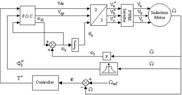
Fig. 1. Indirect field orientation control block diagram
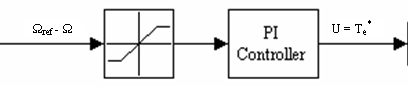
Fig. 2. Proposed PI based controller structure
To evaluate the importance of this proposition, some simulation work of the system command torque given by Fig.1 is presented for different values of the controller gains and the saturation limits.
The parameters of the motor used in the simulation are given in Table 1.
Table 1. Induction Machine Parameters
|
2 pairs of poles, 50Hz |
Rs = 4.85 Ω |
Ls = 27.4 mH |
|
220 V, 6.4 A |
Rr = 3.805 Ω |
Lr = 27.4 mH |
|
2 hp, 1420 rpm |
|
Lm = 25.8 mH |
J = 0.031 Kg∙m2 B = 0.00114 Kg∙m2/s
Fig. 3 shows the variations of the command torque of the system given by fig. 1 using a PI controller without limiter for different values of the integration gain and for Kp= 0.6. The command torque is shown to be unstable for an integration gain greater or equal to 8.
This result leads us to say that if the PI controller gains exceed certain values the system becomes unstable.
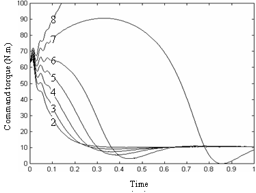
Fig. 3. Command torque variations for different values of the
PI integration gain and Kp= 0.6
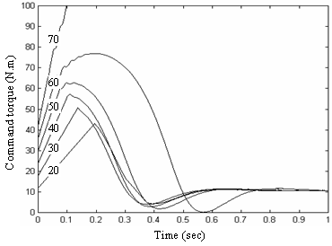
Fig. 4. Command torque variations
for different values of the saturation limits when Kp=0.6 and Ki=8
Fig. 4 shows the variations of the command torque of the system given by fig. 1 using the PI based controller illustrated by fig. 2 for different values of the saturation limits. The controller gains are chosen to be Kp = 0.6 and Ki = 8. The command torque which has been shown to be unstable when no limiter is used becomes stable when a limiter with saturation limits less than 60 is used.
This result leads us to say that an unstable system could be stabilized by adding a limiter with an appropriate value of the saturation limits.
3. Proposed controller parameters settings
The proposed controller parameters have been set using the following two steps:
Step 1. The saturation value has been set to 1, and the PI gain settings Kp = 40 and Ki = 100 have been obtained using the successive trials method.
Step 2. Step 1 is generalised by taking Kp = 40/k and Ki = 100/k where k is a variable representing the saturation limit value.
Fig. 5 shows the variation of the rotor's speed for different values of k. Initially the machine is started up with a load of 10 N∙m at 1s; a 5 N∙m load is applied during a period of 1s.
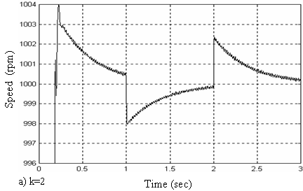
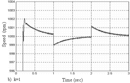
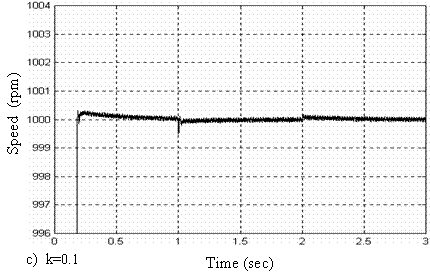
Fig. 5. Rotor's speed variation for different values of the saturation limit k when Kp= 40/k and Ki= 100/k
As the saturation limit decreases, the overshoot and the load disturbance speed dip decreases. Fig. 5a shows that for k = 0.1, the overshoot and the load disturbance speed dip are less than 0.1 rpm (0.01%).
The proposed PI based controller parameters are then chosen to be.
4. PI based controller simulation results
In order to verify the validity of the method of indirect field oriented induction machine drive control using the proposed controller, some simulation work have been performed. The proposed controller with parameters k = 0.1, Kp = 400 and Ki = 1000 is used to replace the controller block of fig. 1.
The parameters of the motor used in the simulation are given in Table 1.
Fig. 6 shows the settling performance of the controller and its disturbance rejection capability.
Initially the machine is started up with a load of 10 N∙m at 2s; a 5 N∙m load is applied during a period of 2s.
The speed of the motor reaches its peak value at 0.19s with 0.025% overshoot. It then settles up with less than 0.02% error at 0.3s.
The load disturbance has almost no effect on the speed of the motor. The controller rejects the disturbances in less than 0.05s with a maximum speed dip of 0.05%.
Fig. 7 shows the speed tracking performance of the proposed controller, under no load. The slope of the trapezoidal command speed is 5000 rpm/s. The speed of the motor tracks the trapezoidal command speed with almost zero speed error since start up. The proposed PI based controller accomplishes a very good speed tracking.
Simulations given by fig. 8 and fig. 9, examine the robustness of the proposed PI based controller to machine parameters changes.
Fig. 8 shows the PI based controller reaction to the variation of the moment of inertia. The motor's speed is simulated, under no load, for moments of inertia equal to J and 2J. Simulation results show that multiplying J by 2 affects the value of the peak time which changes from 0.12s to 0.23s, and that of the overshoot which changes from 0.53% to 0.02%.
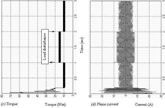
Fig. 6. PI based controller load disturbance

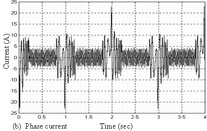
Fig.7. PI based Controller Tracking Performances
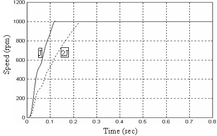
Fig. 8. Variation of the moment of inertia
Fig. 9 shows the PI based controller reaction to F.O.C. detuning problem. The motor is started up with a load of 10 N∙m; at 1s, the rotor's resistance value is doubled. This variation in Rr has no effect on the speed of the motor which is maintained by the proposed controller at its reference value with no visible alteration.
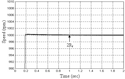
Fig. 9. Variation of the rotor's resistance
5. Structure of the neural network controller
Neural networks can be employed in advanced intelligent control applications by making use of their non linearity learning, parallel processing and generalisation capacities [2-7].
A neural network is constituted of densely interconnected neurones. A neurone is a computing node; it performs the multiplication of its inputs by constant weights, sums the results, shifts it by a constant bias and maps it to a non linear activation function before transferring it to its output.
A feed – forward neural network is organised in layers of neurones: an input layer, one or more hidden layers and an output layer. The inputs to each neurone of the input layer are the inputs to the network. The inputs to each neurone of the hidden or output layer are the outputs from the neurones of the preceding layer.
The mathematical model of a neurone is given by:
 (1)
(1)
Where y is the output from the neurone, (x1, x2, …, xn) are the inputs to the neurone, (w1, w2, …, wn) are the corresponding weights, and b is the bias of the neurone. The activation function f is generally the logarithmic or tangent sigmoidal function. For a logarithmic sigmoidal activation function the output from the neurone is given by:
 (2)
(2)
In a supervised off – line control, the proposed original PI based controller can be replaced by a neural network that learns the mapping form of the controller input – output relationship by adapting its parameters to a training set of examples of what it should do.
To design a neural network for a supervised off – line control, the following steps are necessary:
· Selection of the network structure: The number of layers, the number of neurones for each layer and the number of inputs to the network.
· Presentation of the training data: The network input and the target output vectors.
· Learning: Adaptation of the network parameters (Weights and bias of each neurone) in such a way that the network output gets as close as possible from the target output. Most of the learning algorithms perform the adaptation of weights and biases of the network iteratively until the error between the target vector and the output of the network becomes less than an error goal.
The structure of the neural controller chosen in this paper is given by fig. 10. The controller is a three layers feed – forward linear network with two neurones in the input and hidden layer and one neurone in the output layer. The speed error E is the only input to the controller. The activation functions are logarithmic sigmoid for the input and hidden layer neurones and linear for the output neurone.
The set of examples used to train the network is composed of the original PI based controller simulated input and output values, obtained during starting up, speed tracking and load disturbance of the motor.
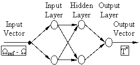
Fig. 10. Neural controller structure
6. Neural controller simulation results
The resulting neural network is used as a numerical controller to replace the proposed original PI based controller in the indirect field oriented induction machine drive control structure illustrated by fig. 1.
Fig. 11 shows the settling performance of the neural controller and its disturbance rejection capability.
Initially the machine is started up with a 10 N∙m load. At 1 s, a 5 N∙m load is added during a period of 1 s.
The speed of the motor reaches its peak value at 0.33 s with 0.04% overshoot and then stays inside a 0.04% error strip.
The load disturbance has almost no effect on the speed of the motor. The controller rejects the disturbances in less than 0.015 s with a maximum speed dip of 0.04%.
Fig. 12 shows the speed tracking performance of the neural controller, under no load. The slope of the trapezoidal command speed is 5000 rpm/s. The trapezoidal command speed is tracked with almost zero speed error since start up.
Simulations given by fig. 13 and fig. 14, examine the robustness of the neural controller to machine parameters changes.
Fig. 13 shows the neural controller reaction to the variation of the moment of inertia. The motor's speed is simulated, under no load, for moments of inertia equal to J and 2J. Simulation results show that multiplying J by 2 affects only the value of the peak time which changes from 0.159 s to 0.303 s.
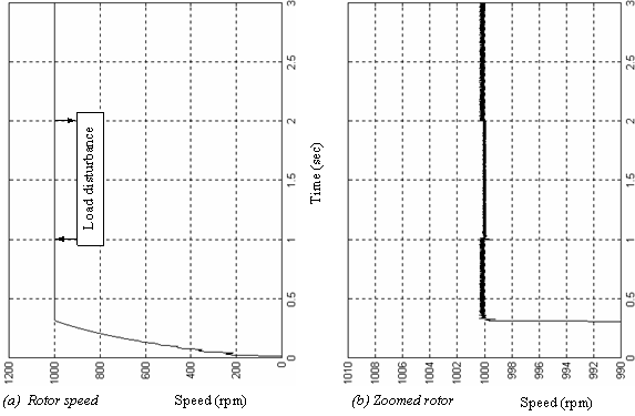
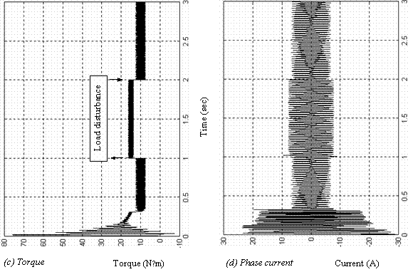
Fig. 11. Neural controller load disturbance
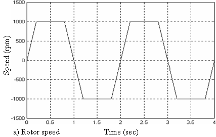
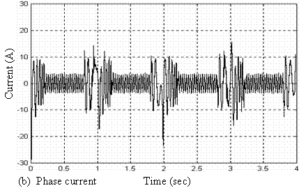
Fig. 12. Neural Controller Tracking Performances
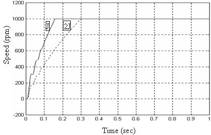
Fig. 13. Variation of the moment of inertia
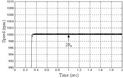
Fig. 14. Variation of the rotor's resistance
Fig. 14 shows the neural controller reaction to F.O.C. detuning problem. The motor is started up with a load of 10 N∙m. At 1s, the rotor's resistance value is doubled. This variation in Rr has no effect on the speed of the motor which is maintained by the neural controller at its reference value with no visible alteration.
Conclusions
In this paper it has been shown that a voltage fed induction motor speed control using indirect field oriented command scheme with a classical PI controller becomes unstable if the gains of the controller exceed a certain value. However, it has been shown by simulation that this instability could be removed by adding a limiter ahead of the PI controller. The resulting PI based controller has been proposed to adjust the speed of a field oriented induction machine drive. Its dynamical performances have been studied and then used to design a robust neural controller.
Simulation results show that both the proposed PI based controller and the designed neural controller realize good dynamic behaviour of the motor, with a rapid settling time, no overshoot, almost instantaneous rejection of load disturbance, a perfect speed tracking and they deal well with parameter variations of the motor. The two controllers seem to be high- performance robust controllers. However this result should be validated experimentally.
References
1. Leonhard W., Control of electrical drives, Springer-Verlag, 1985.
2. Ba - Razzouk A., Cheriti A., Olivier G., Artificial neural networks rotor time constant adaptation indirect field oriented control drives, IEEE PESC, Baveno, June 1986, p. 701-707.
3. Buh M. R., Lorenz R. D., Design and Implementation of Neural Network for Digital Current Regulation of Inverter Drives, Conf. Record of IEEE, IAS Annual Meeting, 1991, p. 415 - 421.
4. Ho E. Y. Y., Sen P. C., Decoupling control of induction motor drives, IEEE Trans. on Ind. Electron., May 1988, 35(2), p. 253 - 262.
5. Bose B. K., Technology Trends in Microcomputer Control of Electrical Machines, IEEE Trans. Ind. Electron., Feb. 1988, 35(1), p. 160 - 17.
6. Leonhard W., Adjustable - speed AC Drives, Proceedings of IEEE, April 1988, 76(4), p. 455 - 471.
7. Psalti A., Sideris A., Yamamura A., Neural controllers, Proceedings of 1st International Conference on Neural Networks, San Diego USA, 1987, 4, p. 551 - 558.