Dynamic
Compensation of the Reactive Energy
using a Fuzzy Controller
Belkacem MAHDAD, Tarek BOUKTIR, and Kamel SRAIRI
Department of Electrical Engineering, University of Biskra
Department of Electrical Engineering, University of Oum El Bouaghi, tbouktir@yahoo.com
Department of Electrical Engineering, University of Biskra, Algeria
Abstract
Solving the capacitor Allocation problem means in general the determination of the optimal location, allocation sizes and switching times for capacitors to be installed on a distribution feeder. The application of capacitors in electric power system is intended for the control of power flow, improvement of stability, voltage profile management, power factor correction, and loss minimisation. The installation of FACTS devices increases the electrical network controllability. This paper describes a simple approach based on logic concept. Fuzzy logic approach is described, which achieves a logical and feasible economic cost of operation without the need of exact mathematical formulation. The results obtained from the fuzzy logic proved that is it a powerful tool for solving such a non - linear problems.
Keywords
Power flow, FACTS, Compensation, Fuzzy controller, Capacitor allocation
I. Introduction
Shunt capacitors applied at a load-end of a circuit applying a load of lagging power factor have several effects:
· Increases voltage level at the load;
· Improves voltage regulation if the capacitor units are properly switched;
· Reduces I2∙R Kilowatt loss;
· Reduces I2∙X Kilovar loss;
· Decreases KVA loading on the source generators and circuits to relieve an overloaded condition and to release capacity of additional local growth.
A review of the literature on reactive power compensation in distribution feeders indicates that the problem of Capacitors Allocation has been extensively researched over the past several decades [7-9]. The solution techniques for the Capacitor Allocation problem can be classified into four categories: Analytical, numerical programming, heuristics, and artificial intelligence based. The choice of which method to use depends on: the problem to be solved, the complexity of the problem, the accuracy of desired results. Once these criteria are determined, the appropriate Capacitor Allocation techniques can be chosen.
The purpose of the transmission networks is to pool power plants and load centers in order to supply the load at a required reliability, maximum efficiency and at a lower cost. As power a transfer grows, the power system can becomes more insecure with unscheduled power flows and higher losses. In this context, as well as the rapid development of self commutated semiconductor devices, have made it possible to design power electronic semiconductor devices, have made it possible to design power electronic equipments. These equipments are well known as Flexible AC Transmission Systems (FACTS) devices, and introduced in 1988 by Hingorani [3]. The objective of FACTS devices is to bring a system under control and to transmit power as ordered by the control centres. It is also allows increasing the usable transmission capacity to its maximum thermal limits.
By using FACTS devices, it is possible to control the phase angle, the voltage magnitude at chosen buses and/or line impedances of a transmission system. Power flow is electronically controlled and it flows as ordered by control centre and consequently the losses and/or cost will be optimized. It has been observed that installation of FACTS devices increases the networks controllability. The use of fuzzy logic has received increased attention in recent years because of it‘s usefulness in reducing the need for complex mathematical models in problem solving. Fuzzy logic employs linguistic terms, which deal with the causal relationship between input and output variables. For this reason, the approach makes it easier to manipulate and solve problems.
II. Problem Formulation
Justification for using fuzzy logic in Reactive Power Sizing and Allocation
Fuzzy logic is a mathematical theory, which encompasses the idea of vagueness when defining a concept or a meaning. It is based on natural language. It is flexible and conceptually easy to understand. It can model nonlinear functions of arbitrary complexity and can be blended with conventional control techniques. In the fuzzy set theory, each inexact or fuzzy relation, such as "Large" or "Small”, is associated with a membership function that represents the degree of certainty for that relation. When the membership function of a fuzzy relation is equal to unity, it is equivalent to a crisp relation. Such ideas are readily applicable to Reactive Power Sizing and Allocation.
Fuzzy Variables
The fuzzy variables associated with Reactive Power Sizing and Allocation Problem 'RPSA' are stated below.
Fuzzy Input Variables:
· Bus voltage;
· Active Power loss;
· Reactive Power loss.
Fuzzy Output Variables:
· Capacitor Sizing (Mvar);
· Bus Allocation (Number of Bus);
Fuzzy sets Associated with 'RPSA'
After identifying the fuzzy variables associated with the Reactive Power Sizing and Allocation, the fuzzy sets defining these variables are selected and normalized between ‘0’ and ‘1’. This normalized value can be multiplied by selected scale factor to accommodate any desired variable.
The sets defining the voltage of buses are as follows:
• VBUS (KV) = {Low, Below Average, Average, Above Average, High}
The Active Power loss (APL) is stated by the following sets:
• APL (MW) = {Low, Medium, High}.
The Reactive Power loss (RPL) is stated by the following sets:
• RPL (Mvar) {Low, Medium, High}.
The Reactive Power Sizing, chosen as the Objective function is given by:
• RPS (Mvar)= {Low ,Below Average, Average, Above Average, High}.
Membership Function
Based on fuzzy sets, the membership functions are chosen for each fuzzy input and output variable.
Fuzzy Rule
The solution procedures start with performing a load flow study to calculate bus voltage, the membership functions of Bus voltage and Power loss are specified subsequently. Candidate location is then identified and size of capacitor is determined, without violating the voltage limits. Finally, a load flow is performed again to find the new bus voltage.
The relation between the fuzzy input and output variables are given by means of the fuzzy rules. There are five subsets for voltage Buses, 3 subsets for Active Power Loss, 3 subsets for Reactive Power Sizing, and it result 45 rules that can be composed (fig. 1).
The diagram of the dynamic compensation is presented by the fig. 2. A fuzzy controller receives information permanently (voltage, power loss) of the electric network and basing on predefined rules, it provided the reactive power as well as the site of the compensation as output elements. The fuzzy controller is sensible to the different perturbations in the electric network (variation of the load, change in the network configuration).
Fig. 1. View Surface of 45 fuzzy rules associated with RPSA
Fig. 2. The main Procedure
III. Power Flow Formulation
In this paper, we apply simplified method to evaluate the power loss using Newton-Raphson iterative method; we first develop a set of simplified line flow equations.
Considering the network test shown in (fig. 3) the system is assumed being a balanced three-phase system.
Fig. 3. Simple network test
![]() (1)
(1)
Sk = Ek·Ik* (2)
![]() (3)
(3)
The real and reactive power flowing are represented by equations (4), (5). The purpose of placing compensating capacitor along the distribution feeders is to lower the total power loss and bring the bus voltages within specified limits:
![]() (4)
(4)
![]() (5)
(5)
where (Vk)min ≤ Vk ≤ (Vk)max correspond to the permissible minimum and maximum voltage, respectively.
IV. Flexible AC Transmission Systems
Methods of Transmission Line Compensation
In this part, we give a detailed appreciation of the effects of applying FACTS controllers from a systems point of view without a specific reference to how work and describe the effect of applying compensation methods to a simple two-ended transmission line model.
Classical Compensation methods
In the analysis of transmission networks for design and operational purposes it is often necessary to include a more rigorous line representation particularly where longer transmission distances are involved. This may include lumped parameters (series reactance, series resistance and shunt capacitor) or where a more exact representation is required this parameters can be distributed.
Uncompensated line
Referring to the simplified model of the uncompensated system of fig 4 the voltage at the mid point of the line is taken to be VM, the real power P, exported along the line is given as:
![]() (6)
(6)
Fig. 4a. Simple power system model

Fig. 4b. The phase diagram
Series Compensation
Series capacitors reduce the total reactance of the transmission line, which is often the main reason for their application. This improves power system stability, reduces reactive power losses and improves voltage regulation of the transmission line.
The power flow along the transmission line is directly proportional to the difference of the phase angle and inversely proportional to the magnitude of the reactance. This concept can be demonstrated by using simple two bus lossless system as shown in fig. 5 with bus 1 having a voltage magnitude V1 at an angle δ1 and bus 2 having a voltage V2 at an angle δ2.
![]() (7)
(7)
Fig. 5. Simple two bus lossless system
The reactance associated with the line limits the power transfer through the system. However, the value of Xl could be decreased, to increase the power transfer, by adding series capacitances as seen in equation 7. One of the important results of series capacitor application is the reduction of the reactive power losses in the system especially in the compensated line.
Shunt Compensation
Figure 6 shows the arrangement of the ideal mid-point shunt compensator which maintains a voltage, VM , equal to the bus bar voltage such that |VS| = |VR| = |VM|. It can be VSVRVM seen that the compensator does not consume real power since the compensator voltage, VM and it’s current IM are in quadrature. Clearly, the power, P transferred from S to the mid-point is equal to the power transferred from the midpoint to R, and is given by:
Fig. 6. Simple model with mid-point shunt Compensation
![]() (8)
(8)
The reactive power generated by the compensator Qp is given by Qp = IMVM:
![]() (9)
(9)

Fig . 7. The phase diagram for shunt compensated line
Flexible AC Transmission Systems
Thyristor Controlled Series Compensator (TCSC)
The model of the network with TCSC is shown in fig 9. The controllable reactance Xc is directly used as a control variable to be implemented in the bus susceptance matrices.

Fig. 9. Equivalent circuit of TCSC
Here the only difference between normal line power flow equation and the TCSC line power flow equation is the controllable Xc.
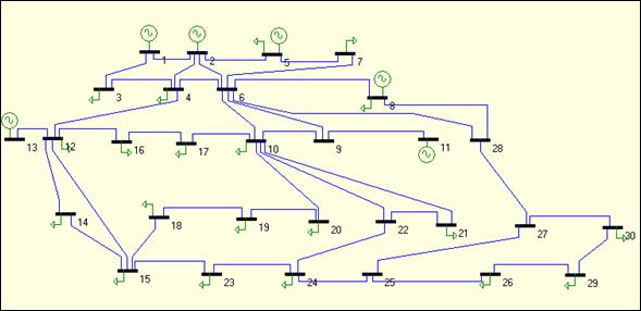
Fig. 10. IEEE 30-bus electrical system topology
Thyristor Controlled Phase shifter (TCPS)
The model of the network with TCSC is shown in fig. 11.

Fig. 11. Equivalent circuit of TCPS
According to the basic circuit theory, the injected equivalent circuit can be obtained from fig. 11 and can be shown in fig. 12.

Fig. 12. Injected model of TCPS
V. Numerical Examples and Computational Results
We consider the test network IEEE 30-bus system. The system consists of 41 lines, 6 generators, 4 tap-changing transformers, and shunt capacitor banks located at 9 buses (figure 10). The results obtained by dynamic compensation are compared with those obtained by static compensation in normal and abnormal situations.
Different states are taken into account:
· normal;
· normal while removing the line between buses 1 and 3;
· static compensation of the network without the line between buses 1 and 3;
· dynamic compensation of the network without the line between buses 1 and 3;
· normal while removing the line between buses 1 and 2;
· static compensation of the network without the line between buses 1 and 2;
· and dynamic compensation of the network without the line between buses 1 and 2.
All the bus voltages of the network during all these states are exposed in the figures 13, 14, 15 and 16. The voltage magnitudes given by the dynamic compensation are better than those given by the static compensation are. In the computation process, a load flow study is first performed to obtain the bus voltages and section losses as well as their corresponding membership values. Subsequently apply the AND operator on the membership Functions of Uv and Up, to determine an optimum bus for the installation of the compensating capacitor. Optimum Bus is the one with the lowest membership function evaluated using the following expressions:
Up(I) = min{Uv(i), Up(i), i =1,2,..., n}
Ul(I) = min{Ul(i), i =1,2,..., n}
where I is the bus with the lowest membership function. The Optimum size of reactive power selected for the installation is the quantity satisfying the voltage constraints. As it is illustrated in table 1, and for a same injected reactive power, the value of real power losses that resides in the electric network decreases in the case of the dynamic compensation, what influences efficiently on the generated power. One can deduct that an adequate implantation of the compensation system of reactive power (dynamic Control of the reactive energy) minimizes power losses of the electrical system, what takes to a considerable improvement of the efficiency of production and transportation.
Fig. 13. Comparison of IEEE 30 bus Network results obtained by dynamic compensation (removing the line 1-3)
Fig. 14. Comparison of IEEE 30 bus Network results obtained by static and dynamic compensation (removing line 1-3)
Fig. 15. Comparison of IEEE 30 bus Network results obtained by dynamic compensation (removing the line 1-2)
Fig. 16. Comparison of IEEE 30 bus Network results obtained by static and dynamic compensation (removing line 1-2)
Table1. Results of the IEEE 30 bus electrical Network
|
State |
Pg (Mw) |
Qg (Mvar) |
∆P (Mw) |
Vmin |
Qinj |
Qtot |
№ Bus |
|
Normal |
301.131 |
151.644 |
17.735 |
0.951 |
0 |
0 |
0 |
|
Normal + remove Line1-3 |
310.946 |
188.470 |
27.546 |
0.921 |
0 |
0 |
0 |
|
Dynamic compensation + remove Line 1-3 |
310.359 |
130.513 |
26.963 |
1.002
|
32.3932 8.0983 2.025 |
34.4182
|
30 5 5 |
|
Normal + remove Line 1-2 |
348.078 |
349.045 |
64.680 |
0.892 |
0 |
0 |
0 |
|
Dynamic Compensation + remove Line 1-2 |
343.919 |
270.053 |
60.520 |
0.955
|
37.9820 9.4955 2.3739 |
49.8514
|
30 5 3 |
|
Static Compensation + remove Line 1-3 |
312.467 |
144.858 |
29.071 |
0.989 |
32.3932 2.025 |
34.4182 |
30 5 |
|
Static Compensation + remove Line 1-2 |
349.995 |
300.898 |
66.597 |
0.942
|
37.9820 9.4955 2.3739 |
49.8514
|
30 5 3 |
Conclusions
In this work, a simple approach based on fuzzy logic concept is applied to Reactive Power Sizing and Allocation Problem, and it is demonstrated with numerical examples.
The comparison of results obtained by this approach and the static compensation proves that fuzzy logic approach gives more accuracy results.
The Reactive Power Sizing and Allocation Problem ‘RPSA’ is quite complex. A wide variety of methods and techniques have been attempted to solve the problem.
It’s clear from results and the existing literature, the global optimal solution still needs further research.
References
[1] Mekhamer S.F., El-Hawary M.E., Mansour M.M., Mostafa M.A., Soliman S.A., State of the art in optimal capacitor allocation for reactive power compensation in distribution feeders, Proceedings of the Large engineering Systems Conference on Power Engineering LESCOPE02 (26-28 June 2002), IEEE, p. 61-75, 2002.
[2] Matos M. A., A new Power flow method for radial Networks, IEEE Bologna PowerTech Conf., Italy, June 23-26, 2003.
[3] Hingorani N. G., High Power Electronics and Flexible AC Transmission System, IEEE Power Engineering review, July 1988.
[4] Bouktir T., Application de la programmation Orientée Objet à l’optimisation de l’écoulement de puissance, Thèse de Doctorat, Université de Batna, 2004.
[5] Nepomuceno E.G., Neto O.M., Takahashi R. H. C., Tavares C. E., A Heuristic Approach to Robust Control design for Power Systems with several Power Flow control needs in Flexible AC transmission System, IEEE Transaction on Power Systems, May 1999.
[6] Alvardo F. L., Solving Power Flow Problems with a Matlab implementation of the Power System Application Data dictionary, Proceeding of FACTS devices, Electrical Power and Energy Systems, 2003.
[7] Su C.-T., Tsai C.-C., A New Fuzzy–Reasoning Approach to Optimum Capacitor Allocation for Primary distribution Systems, Proceedings of the IEEE International Conference on Industrial Technology, 1996.
[8] Masoum M. A. S., Ladjevardi M., Jafarian A., and Fuchs A. F., Optimal Placement, Replacement and Sizing of Capacitor Banks in Distribution Networks by Genetic Algorithm, IEEE Transactions on Power Delivery, Vol. 19, No. 4, October 2004.
[9] Nelson R. J., Bian J., Williams S. L., Transmission Series Power Flow Control, IEEE Transactions on Power Delivery, Vol. 10, No. 1, January 1995.
[10] Momoh J. A., El-Hawary M. E., Adapa R., A Review of Selected Optimal Power Flow Literature to 1993-Part 1: Nonlinear and Quadratic Programming Approaches, IEEE Transactions on Power Systems, Vol. 14, No. 1, February 1999.
[11] Zhuding W., Feng Z., Feng Q. and Hong T., An Analytical Method for Solving Reactive Optimisation on Power Systems, IEEE TENCON, 1993.