Design and Construction of a Hydraulic Ram Pump
Shuaibu Ndache MOHAMMED
Department of Mechanical Engineering, Federal University of Technology, Minna, Nigeria
Abstract
The Design and Fabrication of a Hydraulic Ram Pump (Hydram) is undertaken. It is meant to lift water from a depth of 2m below the surface with no other external energy source required. Based on the design the volume flow rate in the derived pipe was 4.5238 × 10⁻⁵ m3/s (2.7 l/min), Power was 1.273 kW which results in an efficiency of 57.3%. The overall cost of fabrication of this hydram shows that the pump is relatively cheaper than the existing pumps.
Keywords
Hydram; Pump; Volume Flow Rate; Power; Efficiency; Impulse Valve; Delivery Valve.
Introduction
The hydraulic Ram pump or hydram is a complete automatic device that uses the energy in the flowing water such as spring, stream or river to pump part of the water to a height above that of the source. With a continuous flow of water a hydram operates continuously with no external energy source.
A hydram is a structurally simple unit consisting of two moving parts. These are the impulse valve (or waste valve) and the delivery (check) valve. The unit also consists of an air chamber and an air valve. The operation of a hydram is intermittent due to the cyclic opening and cloning of the waste and delivery values. The closure of the waste valve creates a high pressure rise in the drive pipe. An air chamber is required to transform the high intermittent pumped flows into a continuous stream of flow. The air valves allow air into the hydram to replace the air absorbed by the water due to the high pressure and mixing in the air chamber.
Pumps are among the oldest of the machines. They were used in ancient Egypt, China, India, Greece and Rome. Today, pumps are the second most commonly used kind of industrial equipment after the electric motors (Working, 1996).
The first pumps were force pumps and it is interesting that the earliest known example, a pump used by the Greeks in 300 B.C incorporated an air vessel. The use of this device was suspended in the middle-ages and revived in the 16th century when a German translation of the Greek work describing the pump was published. The earliest pump to be used was the hand pump. More advanced pumps were, however, known to the Romans, as shown by the double cylinder force pump now preserved in the British museum, but their use was apparently lost in this century at the end of the Roman Empire.
In Roman times, the first reciprocating pump appeared (250-0 BC) and this remained the main pump type in use for several centuries, operated by hand, animal, water or wind power, mechanical skill developed, and metals came more into use, but the limiting factor with all these older pumps was the relatively low power output which is delivered by them. The highest power developed by wind miles or water wheel were of the order of 10 horsepower (hp). The reciprocating pumps, which relied on suction, could only lift water slightly above 10 metres.
The performance of known types of pumps continued to be improved upon and their range of applications extended. One of such is the peristaltic pump which was developed into a pump for handling slurries of high specific gravity on a cost effective basis. Similarly, the Archimedean screw pump was developed into giant sizes for lifting water to high elevations.
It is reported that the first hydraulic ram pump was built by Whitehurst (1775), which operated manually by the opening and closing of the stopcock. This hydram was able to raise water to a height of 4.9m. The first automatic hydram was invented by Montgolfier in 1796 for raising water in his paper mill. His work was improved upon by pierce (1816), who designed the air or sniffer valve to introduce air into the air chamber and this hydram, which is 300 mm in diameter is reported to have pumped 1700l/min to a height of 48m. Easton and James (1820) were the first to produce hydrams in large scale for commercial purpose. Their rams were used for supplying water to large country houses, farms and village communities.
Calvert (1957) evaluated the performance characteristics of hydraulic ram. The possible independent variables of hydraulic ram installations were considered and with certain assumptions their number reduced using dimensionless parameters such as the Reynolds number, the Froude number, the Mach number, the head ratio and the coefficient of fluid friction. The Reynolds numbers was known to be in effective in machines of practical size and that a range exists over which the Mach number has little influence. The Froude number was found to be the criteria for defining the possibility of operation of the ram and the ram output and efficiency are dependent upon the head ratio.
In 1951, Krol [1] established that it was possible to forecast the behaviour of any automatic hydraulic ram, provided the following properties at a given installation have been determined separately.
· Loss of head due to impulse valve
· Drag coefficient of the impulse valve
· Loss of head in the pipe
· Head lost during the period of retardation.
According to Calvert (1960) the dimension of the drive pipe has a limiting value. This, he established by applying dimensional analysis technique. The relevant parameters were the head ratio, friction coefficient and the dimensionless numbers corresponding to those of Froude, Reynolds and Mach. Hydraulic Ram for village use was developed by V.I.T.A in USA [2]. The Ram was only used for small water supply with the impulse valve being designed to act on a spring mechanism, while the delivery valve is a simple clack valve. A general description of the hydraulic ram which solved most of the design problems was undertaken by Molyneux [3].
Design Analyses
Design Factors
The ram pump consists essentially of two moving parts, the impulse and delivery valves. The construction, basically consist of pipe fittings of suitable designed size.
The main parameters to be considered in designing a hydraulic ram include:
· The difference in height between the water source and pump site (called vertical fall).
· The difference in the height between the pump site and the paint of storage or use (life).
· The quantity (Q) of flow available from the source.
· The length of the pipe from the source to pump site (called the drains pipe).
· The quantity of water required.
· The length of pipe from the storage site (called the delivery pipe)
Determination of Design Parameters for the Hydram
Since a hydram makes use of sudden stoppage of flow in a pipe to create a high pressure surge, the volumetric discharge from the drive pipe is given by:
|
|
(1) |
where, Q = volumetric flow rate through the pipe, r = pipe radius, L = pipe length and
n = speed of revolution.
Also the velocity of fluid flow in the driven pipe is given by
|
|
(2) |
where, Vd = velocity of fluid flow and Ad = area of pipe.
In order to ascertain the nature of the flow (that is whether laminar or turbulent), it was necessary to determine the Reynolds number given by
|
|
(3) |
where, V = velocity of fluid flow, d = pipe diameter and ![]() = kinematic
viscosity.
= kinematic
viscosity.
The friction factor f can be derived mathematically for laminar flow, but no simple mathematical relation for the variation of f with Reynolds number is available of turbulent flow. Furthermore, Nikuradse et al. found that the relative roughness of the pipe (the ratio of the size of the surface imperfection to the inside diameter of the pipe) affects the value of f too.
For smooth pipes Blasius suggested that for turbulent flow
|
|
(4) |
where, f = frictional factor of the pipe and Re is Reynolds number.
The DarcyWersbach formula is the basis of evaluating the loss in head for fluid flow in pipes and conduits and is given by
|
|
(5) |

where, g = acceleration due to gravity, L = length of the pipe, V= fluid velocity and d = pipe diameter.
The velocity of fluid flow in the Tjunction is given by
|
|
(6) |
where Q = is the volumetric fluid discharge and AT = pipe x-sectional area at T-junction.
Loss due to sudden enlargement at the T-junction is expressed as
|
|
(7) |
Other losses of head, as in pipe fittings are generally expressed as
|
|
(8) |

Since the head (H) contributed to water acceleration in the driven pipe, this acceleration is given by
|
|
(9) |

The value of K and f can be found from standard reference handbooks/textbooks. Eventually this flow will accelerates enough to begin to close the waste valve this occurs when the drag and pressure in the water equal the weight of the waste value. The drag force given by equation
|
|
(10) |
The force that accelerates the fluid is given by
|
|
(11) |
The pressure at point is obtained by divided the force F in Equation (11) by the area A.
|
|
(12) |
The power required can k calculated using this expression
|
|
(13) |
The efficiency of the hydram is given by
|
|
(14) |
Results
The calculated design parameters for the hydraulic ramp pump are done based on the following specifications of supply and delivery heads from a published manual on the hydraulic ram for pumping water by WATT [4]. Table 1 gives the values of the calculated parameters.
Design Specifications:
· Supply Head = 1.5m
· Delivery Head = 2.87m
Table1. Results of calculated parameters
|
Parameters |
Values |
|
Drive pipe diameter Drive pipe length Speed of diaphragm Flow discharge in drive pipe Total head losses in the system Force on waste valve Pressure at waste valve Power developed by the hydram Hydraulic pump efficiency |
25 mm 90 mm 96 beats/min 2.3 l/min 11.71 ×10⁻⁴m 7.2 N 3668 kN/m2 1.273 kW 57.3 % |
Mode of Operation and Performance Evaluation
Operation Principle
The energy required to make a Ram lift water to a higher elevation comes from water falling downhill due to gravity. As in all other water powered devices, but unlike a water wheel or turbine, the ram uses the inertia of moving part rather than water pressure and operates in a cycle based on the following sequences.
Sequence I
Water from the source flow through the drive pipe (A) into the ram pump body, fills it and begins to exit through the waste or impulse valve (B). The check valve (C) remains in its normal closed positions by both the attached spring and water pressure in the tank (D) and the delivery pipe (E) (no water in the tank prior to start up). At this starting point there is no pressure in tank (D) and no water is being delivered through exit pipe (E) to the holding tank destination. See Figure 1.
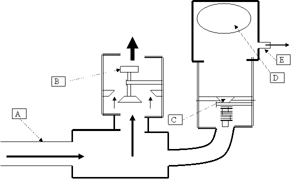
Figure 1. Hydraulic Ram Sequence I
Sequence II
Water entering the pump through the drive pipe (A) has its velocity and pressure being directed out of waste valve (B) as illustrated in Figure 2.
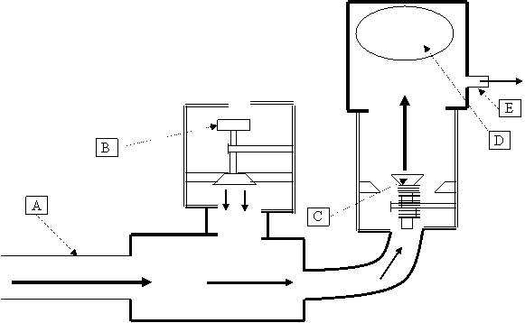
Figure 2. Hydraulic Ram Sequence II
Sequence III
Water has stopped flowing through the drive pipe (A) as a shock wave created by the water hammer travels back up the drive pipe to the settling tank. The waste valve (B) is closed. Air volume in the pressure tank (D) continues expanding to equalize pressure, pushing a small amount of water out of the delivery pipe (E). See the illustration in Figure 3.
Sequence IV
The shock wave reaches the holding tank causing a gasp for water in the drive pipe (A). The waste valve (B) opens and the water in the drive pipe (A) flows into the pump and out of the waste valve (B). The check valve (C) remains closed until the air volume in the pressure tank (D) has stabilized and water has stopped flowing out of the delivery pipe (E). At this point sequence 1 begins all over again.

Figure 3. Hydraulic Ram Sequence III
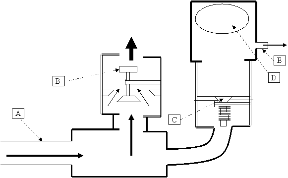
Figure 4. Hydraulic Ram Sequence IV
Installation
The installation of a hydram pump (see figure 5) is such that the cycle of its operation is dependent upon the length of the drive pipe. It is recommended that the pump should complete a cycle every 1.5 to 2 seconds. If a cycle is either too fast or too slow the output performance will suffer. Too fast of a cycle is a symptom of either a drive pipe being too short or the waste valve needing more weight. Too long of a cycle is caused by an excessively long drive pipe or so much weight on the waste valve that the column of water takes a longer time to overcome, causing it to close suddenly. This creates a momentary high pressure Water hammer that in turn force the check valve (C) to open allowing a high pressure pulse of water to enter the pressure tank (D). The air volume in the pressure tank is compressed causing water to begin flowing out of the delivery pipe (E) and at the same time closing the check valve (C) so as to prevent reverse flow. As the air volume in pressure tank (D) continues to expand, water is forced out of the delivery pipe (E) to the holding tank.
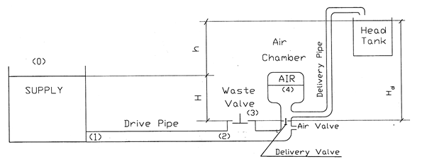
Figure 5. A Typical Hydraulic Ram Installation
Construction of the Hydram
In designing an efficient hydraulic ram pump, the most basic decision involves the choice of materials. Beside their availability and cost which are always of primary consideration, materials are also chosen on the basis of their properties. Materials that prolong the life of pumps are largely suitable. Galvanized metal plates and pipes were used for the construction. Figure 6 shows the fabricated hydram pump system discussed in the study.
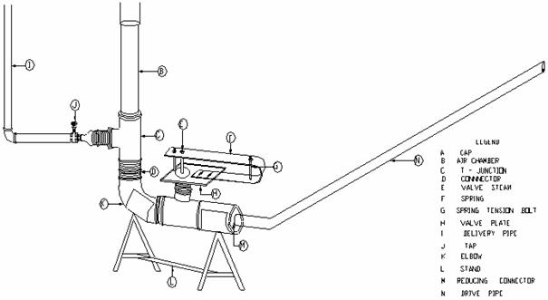
Figure 6. Fabricated Hydram Pump System
Conclusion
The present study is centred towards the development of a hydraulic ram pump that would conveniently alleviate the problem of water supply to the mass populace. Ideally, different combinations of the supply and delivery heads and flows, stroke length and weight of the impulse valve, length to diameter ratio of the drive pipe, volume of the air chamber and size of the snifter valve, etc. were tried to come up with an optimum size of a hydram pump presented in this study.
References