Modelling of a Gas Absorption Column for CO2-NaOH System under Unsteady-State Regime
Moses Aderemi OLUTOYE and Elizabeth Jumoke ETERIGHO
Chemical Engineering Department, Federal University of Technology, Minna, Nigeria
E-mail(s): remnickolutoye@yahoo.com, jummyeterigho@yahoo.com
Abstract
The research work on the unsteady state behavior of gas absorption column for CO2-NaOH system was carried out using the armfield gas absorption column. A model equation was developed by considering material balance around the system. The concentrations of the inlet and outlet liquid streams and the gas outlet stream varied as functions of time, while all other parameters, gas inlet stream concentration, and tank volume, were constant. Model equations were derived for the time dependent parameters and the model compared with experiments conducted for duration of 90 minutes showed that 0.2 gram mole/litre of NaOH solution reacts with CO2 to give 0.1 gram mole/litre of Na2CO3.This clearly shows that the results of experiments conducted were in agreement with the model results.
Keywords
Modelling; Unsteady state; Gas absorption column.
Introduction
The consideration of gas absorption under unsteady sate regime is quite novel. Most gas absorption systems operate under steady state regime. Such unsteady state processes find application in a variety of chemical process industries. The absorption of carbon dioxide into sodium hydroxide is accompanied by chemical reaction to form sodium carbonate as product. This process is known as chemisorptions. It is used in the extraction of carbon dioxide from refinery gases and the product is usually not striped since it has some economic value. The steady state process absorption of the CO2-NaOH system has been studied previously [1] where the rate of absorption, the rate of transfer of material through the gas film will be the same as that through the liquid film, and the generation for mass transfer of a component is described by equation:
N'A = KG (PAG PAi) = KL (CAi CAL)
This paper aims to propose a set of model equations for the said system under unsteady state conditions.
Absorption
The removal of one or more selected components from a mixture of gases by absorption into a suitable liquid is the second major operation of chemical engineering that is based on interface mass transfer controlled largely by rates of diffusion [1]. Gas absorption is an operation in which a gas mixture is contacted with a liquid for the purposes of preferentially dissolving one or more components of the gas and to provide a solution of them in the liquid.
Absorption processes can be divided into two groups, those in which the process is solely physical and the one accompanied by a chemical reaction. In gas absorption equipment design, intimate contact of the gas with the liquid is required [2].
Absorption associated with chemical reaction
There are a number of cases in which a gas, on absorption, reacts chemically with a component of the liquid phase. Thus, in the absorption of carbon dioxide by caustic soda, the carbon dioxide reacts directly with the caustic soda and the process of mass transfer is thus made much more complicated [1]. In such processes, the conditions in gas phase are similar to those of an entirely physical absorption process, but in the liquid phase, there is a liquid film followed by a reaction zone.
An advantage of absorption plus reaction is the increase in the mass-transfer coefficient. Some these increments come from a grater effective interfacial area, since absorption can now take place in nearly stagnant regions (static holdup) as well as in the dynamic liquid holdup [3].
Derivation of model equation\
The process of interest is the absorption of carbon dioxide into dilute solution of caustic soda using the armfield UOP gas absorption column. The model attempts to show that the rate of absorption can be determined exclusively by material balance consideration. In an attempt to develop a model for the unsteady state process in an absorption column for CO2-NaOH system, the following assumptions were made:
· The solvent is recycled without regeneration.
· The absorption process is counter current.
· There is negligible heat effect in the column thus; the column operates with constant temperature.
· The rate of absorption with chemical reaction is proportional to that without chemical reaction.
· The absorbent is of dilute concentration.
· The NaOH concentration is depleted on reacting with CO2 at a certain time, t.
A material balance taken over the system gives.
Material balance around the column
|
(CO2 lost by gas) = (Co2 taken up by liquid) G(CG1 CG2(t)) = L(CL1(t) CL2(t)) |
(1) |
Material balance around the tank
In = Out + Accumulation
|
|
(2) |
There are three time dependent parameters and only two material balance equations. A third equation is formed by modeling CL1(t) as a function of time.
Trial of several equations gives a mutable equation of the form
|
CL1(t) = ko(1-e-k2t) using polymath 3 [4] |
(3) |
This equation came about by developing the equation of the line that fits the experimental values of CL1(t).
Equation (2) is solved by the use of numerical method [4,5,6] and analytically using model equation (3).
|
|

A diagrammatic representation of the absorption column is shown in figure 1.
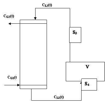
Figure 1. Diagrammatic representation of the absorption column
The sampling points are S4 and S5. The holding tank, V is assumed to be as that of a continuous stirred tank system such as CL2(t) the liquid concentration into the column is the same as within the tank.
Substituting equation (3) into (4)
|
|
(4) |
|
|
|
Using the integration factor multiply by eRt.
|
|

|
|
(5) |

Rearranging equation (1) gives
|
|
(6) |

Equation (3), (5) and (6) are the model equations that will give the values CL1(t), CL2(t) and CG2(t) respectively. The constant term ko is obtained by determining the number of moles of CO2 that react with NaOH [7]. The reaction is shown below.
|
2NaOH + CO2 → Na2CO3 aA + bB → product |
Thus,
|
a/b = n2/n1 = C2V2/C1V1 |
and
|
CL1(t) = b/a CL2(t) |
|
CL1(t) = ko at t = 0 |
The overall equation for the reaction is given by:
|
Na2CO3 + 2HCL → 2NaCL + H2O + CO2 |
Methodology
7.5 litters of IM solution of caustic soda was prepared and poured in 30 litres of water to make 37.5 litters of 0.2M-solution of caustic soda that was poured into the reservoir tank at the base of the column. The gas flow control valves were closed. The liquid pump and the compressor were switched on and the flow of caustic soda through the column and the airflow were regulated to 3litres/min and 30 litters/min respectively. The pressure-regulating valve on the carbon dioxide cylinder was carefully opened and the flow of CO2 to the column was 3 litters/min. Product samples were withdrawn after 30mins for analysis using titrimetric method.
Results
The table below shows the changes of carbon dioxide concentration with time.
Table 1. Table showing the changes in concentration of CO2 with time
|
Time (sec) |
CL1 gram mole/liter (experimental) |
CL1 gram mole/l (model) |
CL2 gram mole/liter (experimental) |
CL2 gram mole/l (model) |
|
0 |
0 |
0 |
0 |
0 |
|
1800 |
0.070 |
0.0711 |
0.060 |
0.0498 |
|
3600 |
0.095 |
0.0923 |
0.080 |
0.0840 |
|
5400 |
0.097 |
0.0987 |
0.090 |
0.0960 |
The table below shows the concentration of carbon dioxide in sodium hydroxide with time.
Table 2. Table of concentration of CO2 in NaOH with time
|
Time,t(seconds) |
CL1(t) model (gram mole/litre) |
CL2(t) polymat(3) (gram mole/litre) |
|
0 |
0 |
0 |
|
1800 |
0.0711 |
0.0498 |
|
3600 |
0.0923 |
0.0840 |
|
5400 |
0.0987 |
0.0960 |
The table below shows the results of the analysis of liquid sample from the sump (inlet) tank S5.
Table 3. Table of analysis of liquid sample from sump tank inlet S5
|
Time from start (sec) |
Analysis of liquid sample from inlet tank |
|
|
Amount of HCl needed to neutralize all bicarbonate (T2-T1) ml |
Difference between total acid required for neutralization of HCO3 and OH alone (T2-T3) |
|
|
0 |
1.40 |
2.20 |
|
1800 |
16.50 |
32.40 |
|
3600 |
24.60 |
38.50 |
|
5400 |
38.60 |
46.60 |
|
Time from start (sec) |
Concentration of NaOH in original sample T3/50 * 0.2M (gram mole/litre) |
Concentration of Na2CO3 in original sample (T2-T3)/50 * 0.2 *0.5 (gram mole/litre) |
|
0 |
0.20 |
0.0 |
|
1800 |
0.04 |
0.06 |
|
3600 |
0.01 |
0.08 |
|
5400 |
0.003 |
0.09 |
The table below shows the results of the analysis of liquid sample from the sump (inlet) tank S4.
Table 4.Table of analysis of liquid sample from sump tank inlet S4
|
Time from start (sec) |
Analysis of liquid samples from sump tank inlet S4 |
||||
|
T1(ml) |
T2(ml) |
T3(ml) |
Concentration of NaOH (gram mole/litre |
Concentration of Na2CO3 (gram mole/litre) |
|
|
0 |
31.100 |
42.300 |
20.600 |
0.200 |
0.000 |
|
1800 |
18.900 |
41.500 |
4.850 |
0.020 |
0.070 |
|
3600 |
15.000 |
49.000 |
1.400 |
0.010 |
0.095 |
|
5400 |
9.500 |
49.000 |
0.040 |
0.002 |
0.097 |
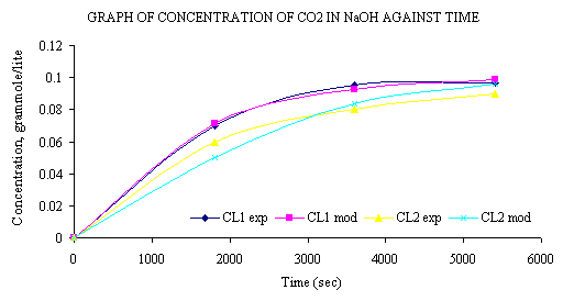
Figure 2. Graph of concentration of CO2 in NaOH against time
For the model:
Limiting value of CO2 concentration, ko = 0.101348 gmoles/litre
Time constant, k2 = 0.67
Air Flow rate, G = 0.5L/S
Tank Volume, V = 37.5L
CO2 inlet concentration, CG1 = 4.926 * 10-3 gmol/L
Discussion
At the initial NaOH concentration value of 0.2M the concentration of CO2 (CL1(t)) leaving the column is zero. The reaction proceeds till the concentration of CO2 in the tank reaches a limiting value of 0.1M. This value remains unchanged since the entire volume of NaOH has reacted with CO2 to form Na2CO3. This value agrees with the stoichiometry of the equation.
|
CO2 + 2NaOH → Na2CO3 aA + bB → product |
where a = 0.1 and b = 0.2. From the plot of experimental values of CL1(t) and CL2(t) compared with model values of CL1(t) and CL2(t), we see that within the limits of experimental error, experiment and model agree. In Figure 2 a decrease in the concentration of NaOH was observed. At a time t=0, NaOH has a value of 0.2M and at t=5400 seconds it attains a value of about 0.003M which is approximately is equal to zero. Thus, it can be said that at such reaction conditions as those of the experiment conducted to validate the model, NaOH is completely converted to Na2CO3 after any time t = 5400 seconds. The concentration of CO2 in the tank, V, continues to increase until it reaches a value of about 0.098 gram mole/litter, which is close to 0.1M, the value of the limiting CO2 concentration, ko. This agrees with the mole ratio of 2:1 for NaOH to CO2 in the reaction that gives the product as Na2CO3.The model result, within limit of experimental error, the model equation was derived in such manner that the limiting value of CO2 concentration, ko, would be half the value of NaOH concentration.
Conclusion
The model derived has been seen to agree with experiment, which was conducted under unsteady state regime. Thus, the values of the carbon dioxide concentrations in caustic soda can be predicted if given initial NaOH concentrtion, volume of NaOH and flow rate. This naturally translates into the Na2CO3 formed. The model has not yet been tested to verify the CO2 outlet concentration in the air stream, CG2(t).
References
1. Coulson J.M., Richardson J.F., Chemical Engineering, Vol.2, 4th Ed., Butterworth-Heinman Pub., London, 1996, pp. 530-550.
2. Treybal R.E., Mass Transfer Operations,3rdEd., McGraw-Hill Book Co.New York, 1980, pp. 281 - 282.
3. McCabe W.L., Smith J.C., Unit Operations of Chemical Engineering, 5th Ed. McGraw-Hill Book Co, Singapore, 1993, pp. 681-729.
4. Himmelblau D. M, Basic Principles and Calculations in Chemical Engineering, Prentice-Hall international, New York, 1996.
5. Babatunde A. O., Principles of Mathematical Modelling and Analysis in Chemical Engineering,Done Publishers,University of Lagos, Nigeria, 1985, pp. 5-12.
6. Jenson V. G., Jeffereys G. V., Mathematical Methods in Chemical Engineering, U.S Ed., Academic Press Inc. (London) Ltd., London, 1991, pp.25-70.
7. Meyers R., Encyclopedia of Physical Science and Technology, Vol. 9, Harcourt Brace Jovanovich Publishers, London, 1988, pp. 519-528.
Nomenclature
a = number of moles of CO2
b = number of moles of NaOH
CL1(t) = concentration of CO2 in NaOH leaving the column with time (gram mole/litter)
CL2(t) = concentration of CO2 in NaOH entering the column with time (gram mole/litter)
CG2(t) = concentration of CO2 in gas stream leaving the column with time (gram mole/litter)
CG1 = concentration of CO2 in gas stream entering the column (gram mole/litter)
G = air flow rate (litters/sec)
Ko = limiting value of CO2 concentration in NaOH solution (gram mole/litter)
k2 = time constant
L = Liquid flow rate (litters/sec)
V = tank volume (litters)