Sliding Controller of Switched Reluctance Motor
Ahmed TAHOUR1,*, Abdelkader MEROUFEL2, Hamza ABID3, Abdel Ghani AISSAOUI2
1 University of Bechar, 08000, Algeria
2 IRECOM Laboratory, University of Sidi Bel Abbes, 22000, Algeria
3 AML Laboratory, University of Sidi Bel Abbes, 22000, Algeria
*Corresponding Author. E-mail: tahourahmed@yahoo.fr
Abstract
This paper presents an application of sliding mode control for switched reluctance motor (SRM) speed. The sliding mode technique finds its stronger justification in the utilization of a robust control law to model uncertainties. A sliding mode controller of the motor speed is then designed and simulated. Digital simulation results shows that the designed sliding speed controller realises a good dynamic behaviour of the motor, a perfect speed tracking with no overshoot and a good rejection of impact loads disturbance. The results of applying the sliding mode controller to a SRM give best performances and high robustness than those obtained by the application of a conventional controller (PI).
Keywords
Switched Reluctance Motor; PI; Sliding Mode; Speed Control.
Introduction
Switched reluctance motors (SRMs) can be applied in many industrial applications due to their cost advantages and ruggedness. The switched reluctance motor is simple to construct. It is not only features a salient pole stator with concentrated coils, which allows earlier winding and shorter end turns than other types of motors, but also features a salient pole rotor, which has no conductors or magnets and is thus the simplest of all electric machine rotors. Simplicity makes the SRM inexpensive and reliable, and together with its high speed capacity and high torque to inertia ratio, makes it a superior choice in different applications.
Sliding mode control has long proved its interests. Among them, relative simplicity of design, control of independent motion (as long as sliding conditions are maintained), invariance to process dynamics characteristics and external perturbations, wide variety of operational modes such as regulation, trajectory control [1], model following [2] and observation [3].
However, the motor is highly nonlinear and operates in saturation to maximize the output torque. Moreover, the motor torque is a nonlinear function of current and rotor position. This highly coupled nonlinear and complex structure of the SRM make the design of the controller difficult [4].
The application of sliding mode in switched reluctance motor speed control is described in this paper.
SRM Model
Description of the system
In a switched reluctance machine, only the stator presents windings, while the rotor is made of steel laminations without conductors or permanent magnets. This very simple structure reduces greatly its cost. Motivated by this mechanical simplicity together with the recent advances in the power electronics components, much research has being developed in the last decade. The SRM, when compared with the AC and DC machines, shows two main advantages:
· It is a very reliable machine since each phase is largely independent physically, magnetically, and electrically from the other machine phases;
· It can achieve very high speeds (20000 - 50000 r.p.m.) because of the lack of conductors or magnets on the rotor;
The switched reluctance machine motion is produced because of the variable reluctance in the air gap between the rotor and the stator. When a stator winding is energized, producing a single magnetic field, reluctance torque is produced by the tendency of the rotor to move to its minimum reluctance position [5].
A cross-sectional view is presented in figure 1.
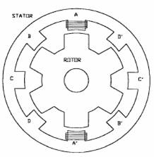
Figure 1. Switched reluctance motor
The schematic diagram of the speed control system under study is shown in figure 2. The power circuit consists with the H-bridge asymmetric type converter whose output is connected to the stator of the switched reluctance machine. Each phase has two IGBTS and two diodes. The parameters of the switched reluctance motor are given in the Appendix [5, 6].
The SMC inputs are obtained by manipulating the speed reference and feedback, while the SMC output is integrated to produce the current reference.
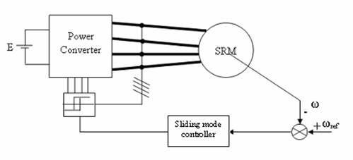
Figure 2. Control of SRM
Machine equation
The switched reluctance motor has a simple construction, but the solution of its mathematical models is relatively difficult due to its dominant non-linear behaviour. The flux linkage is a function of two variables, the current I and the rotor position (angle θ).
The mathematical model from the equivalent circuit is:
|
|
(1) |
with j = 1, 2, , 4
Then we can write:
|
|
(2) |
In which: ω = dθ/dt
The motion equation is:
|
|
(3) |
It is a set four non-linear partial differential equations, its solution neglecting the nonlinearity of magnetic saturation.
|
|
(4) |
It can be written as
|
|
(5) |
|
|
(6) |
The average torque can be written as the superposition of the torque of the individual motor phases:
|
|
(7) |
where V - the terminal voltage, I - the phase current, R - the phase winding resistance, ψ - the flux linked by the winding, J - the moment of inertia, f - the friction, L(θ) - the instantaneous inductance and Te is the total torque.
Srm Sliding Mode Speed Controller
Sliding Mode Principle
Sliding modes is phenomenon may appear in a dynamic system governed by ordinary differential equations with discontinuous right-hand sides. It may happen that the control as a function of the system state switches at high frequency, this motion is called sliding mode. It may be enforced in the simplest tracking relay system with the state variable x(t) [7, 8]:
|
|
(8) |
With the bounded function f(x) |f(x)| < f0, f0 constant and the control as a relay function (figure(3)) of the tracking error e = r(t) - ∂x/∂t, where r(t) is the reference input and u is given by :
|
|

or u = u0sign(e) , u0 = constant
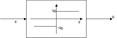
Figure 3. Relay control
The values of e and
|
|
have different signs if
|
|
Sliding Mode Controller
The equivalent total phase power becomes [9, 10]
|
|
(9) |
The electromagnetic torque over the switching period is then
|
Te = (Vdc/ω)Ic(t) |
(10) |
If Ic(t) = Kt(ω/Vdc)It(t) then electromagnetic torque can be further simplified as
|
Te = KtIt(t) |
(11) |
Where Kt is a proportional torque constant and It(t) is the equivalent dc-link current providing electromagnetic torque.
The electromagnetic dynamic model of a switched reluctance motor and loads can be expressed as follows [11,12, 13]:
|
|
(12) |
From (11) and (12), (13) can be obtained:
|
|
(13) |
Speed control can be implemented by a sliding-mode variable structure controller, but a discontinuous torque control signal would cause chattering of the speed response. In order to enable smooth torque control and reduce the chattering problem It(t) must be smoothed according to (11). The phase variable state representation of Fig. 4 can be used to develop the required control scheme. It can be simplified as:
|
|
(14) |

Where x1 = ωd ω, ωd is the demand rotor speed, x2 =∂w/∂t, and U is a control signal which is used to control the speed error dynamics, irrespective of drive system parameter variations.
The sliding line in the phase plane diagram [Fig. 4] can be described as follows:
|
S = ωref ω |
(15) |
from the equation (13) and (15) , we can be obtains
|
|
(16) |
the current of control is given by
|
|
with
|
|
(17) |
|
|
|
To satisfy the existence condition of the sliding-mode speed controller, the following must be satisfied:
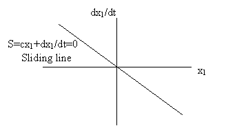
Figure 4. A prescribed sliding line in phase plane
|
|
(18) |
The controller can be designed as follows:
|
|
where
|
|
(19) |
|
|
|


a and b are proportional and derivative gain constant respectively, and α1, α2, β1 and β2 are real constants.
Simulation Result
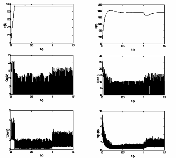
To show the sliding mode controller performances we have simulated the system described in figure 1. The simulation of the starting mode without load is done. The test consisted in to control the motor speed at ωref = 100 rad/s and to apply an external load at t = 1s with a value of Tr = 0,7 N.m. The simulation is realized using the SIMULINK software in MATLAB environment. Figure 5 shown the performances of the sliding mode controller.
Sliding controller PI controller
Figure 5. Simulation results of speed control
The PI controller lacks flexibility regarding changes of the SRM operating point, which means that parameters Kp and Ki are only valid for a certain operating region figure 5.
Figure 5 shows the very good performances reached by the sliding mode controller. Indeed, one notes that the overshoot is less important in the case of the sliding regulator, with a best response time without increasing the overshoot.
For this test, the sliding controller proves to be well more robust because the speed curve is hardly of its reference. On the other hand, the speed signal evolution obtained with the PI controller deviates about 10% from its reference value (figure 5). The speed tracking is satisfactory, and the torque ripple is low. These results demonstrate the robustness of the drive under unpredictable load conditions. The decreasing speed oscillations with the PI controller are owed to a slower reaction of the current, as shown in figure 5.
Robustness
In order to test the robustness of the proposed control, we have studied the speed performances. Two cases are considered:
1. Inertia variation,
2. Stator resistance variation.
The figure 6 shows the tests of the robustness: a) The robustness tests concerning the variation of the resistances, b) the robustness tests in relation to inertia variations
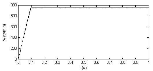
Figure 6.a. Test of robustness - Different values of resistance of stator (1-R/2, 2-R, 3-2R)
Figure 6-b shows the parameter variation does not allocate performances of proposed control. The speed response is insensitive to parameter variations of the machine, without overshoot and without static error. The other performances are maintained.
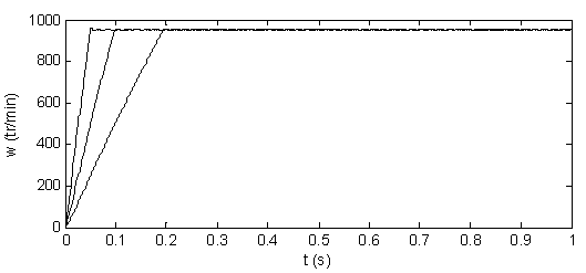
 Figure 6.b. Test of robustness - Different values of moment of inertia
(1-J/2, 2-J, 3-2J)
Figure 6.b. Test of robustness - Different values of moment of inertia
(1-J/2, 2-J, 3-2J)
Conclusions
The paper presents a new approach to robust speed control for switched reluctance motor. It develops a simple robust controller to deal with parameters uncertain and external disturbances and takes full account of system noise, digital implementation and integral control. The control strategy is based on SMC approaches.
The simulation results show that the proposed controller is superior to conventional controller in robustness and in tracking precision. The simulation study clearly indicates the superior performance of sliding control, because it is inherently adaptive in nature. It appears from the response properties that it has a high performance in presence of the plant parameters uncertain and load disturbances. It is used to control system with unknown model. The control of speed by SMC gives fast dynamic response without overshoot and zero steady-state error.
Appendix
Phase number 4; Number of stator poles 8; 22.6° pole arc; Number of rotor poles 6; 23.0° pole arc; Maximum inductance 9.15 mH (unsaturated); Minimum inductance 1.45 mH; Phase resistance R = 0.3Ω; Moment of inertia J = 0.0027Kg/m2; Friction f = 0,0067 Nm/s; Inverter voltage V = 100 V.
References
1. Utkin V., Guldner J., Shi J., Sliding mode control in electromechanical systems, Ed Taylor and Francis, 1999.
2. Utkin V. I., Sliding mode control design principles and applications to electric drives, IEEE Trans. Industrial Electronics, 1993, 40(1), p. 23-36.
3. Panda S. K., Dash P. K., Application of nonlinear control to switched reluctance motors: A feedback linearization approach, Proc.Inst. Elect. Eng., 1996, 143(B/5), p. 371-379.
4. Perruquetti W., Barbot J. P., Sliding Mode Control In Engineering, Ed Marcel Dekker, 2002.
5. Soares F. P. J., Costa Branco Simulation of a 6/4 Switched Reluctance Motor Based on Matlab/Simulink Environment, Aerospace and Electronic System, IEEE Transactions, 2001, 37, p. 989-1009.
6. De Carlo R. A., Zak S. H., Matthews G. P., Variable structure control of nonlinear multivariable systems: a tutorial, Proceedings IEEE, 1988, 76(3), p. 212-232.
7. Hung J. Y., Gao W., Hung J. C., Variable structure control: a survey, IEEE Trans. Industrial Electronics, 1993, 40(1), p. 2-22.
8. Taylor D. G., Nonlinear control of electric machines: An overview, IEEE Control Systems Magazine, 1994, 14(6), p. 41-51.
9. Slotine J. J. E., Hedrick J. K., Misawa E. A., On sliding observers for nonlinear systems, Transactions of the ASME: Journal of Dynamic Systems Measurement and Control, 1987, 109, p. 245-252.
10. Ho E. Y. Y., Sen P. C., Control dynamics of speed drive systems using sliding mode controllers with integral compensation, IEEE Trans.Ind. Applicat., 1991, 27, p. 883-892.
11. Bose B. K., Sliding mode control of induction motor, In Proc. IEEEIAS Annu. Meeting, 1985, p. 479-486.
12. Chuang T.-S., Pollock C., Robust Speed Control of a Switched Reluctance Vector Drive Using Variable Structure Approach, IEEE Transactions On Industrial Electronics, 1997, 44(6), p.800-808.
13. McCann R. A., Islam M. S., Husain I., Application of a Sliding-Mode Observer for Position and Speed Estimation in Switched Reluctance Motor Drives, IEEE Transactions On Industrial On Industry Applications, 2001, 37(1), p. 51-58.