Evaluation of Causes of Retaining Wall Failure
Mu’azu Mohammed ABDULLAHI
Civil Engineering, F.U.T., P.M.B. 65, Minna, Niger State, Nigeria.
E-mail: mmuazuabdulahi@yahoo.co.uk
Abstract
Retaining structures are vital geotechnical structure, because the topography of the earth surface is a combination of plain, sloppy and undulating terrain. The retaining wall resists thrust of a bank of earth as well as providing soil stability of a change of ground elevation. Earth pressures on retaining wall are designed from theories of Soil Mechanics, but unfortunately the engineers using them do not always realize the significance of the assumption in their development. This is usually accompanied by with failure and partial failures because of designed based on rules and formulae that fit only limited conditions. In addition there are also problems of using bad backfill materials without taking precautionary measures against built–up of hydrostatic pressure by provision of drainage and also poor workmanship.
Keywords
Retaining wall, earth pressure, hydrostatic pressure, backfill
Introduction
The term retaining wall has traditionally been applied to free – standing walls whose purpose is to resist the thrust of a bank of earth or other materials. Some of these walls are well designed and are functional, while others may have the appearance of strength, but other may be more a show piece. Retaining wall may also provide soil stability at a change ground elevation.
A retaining wall is a permanent, relatively rigid structure of cribbing masonry or concrete that supports a mass of soil. It substitutes the steep face of the wall for the gentle natural slope of the earth to provide useable space in highway and rail road cut, in and around building and also in structures below ground level. The design philosophy deals with the magnitude and distribution of lateral pressure between a soil mass and an adjoining earth retaining structure. This involves prediction of lateral pressure and deformation by considering the initial stress condition in the soil, the stress – strain relationship for the soil and the boundary condition describing soil structure interaction. Such a solution would be extremely complex and in practice simplified methods are used.
Real problems in lateral earth pressure involve more than simple loads produces by soil against a retaining wall. Earth pressure is not a unique property of the soil or rock, but it is a function of the material that the retaining structure must support, of the loads that the soil behind the structure must carry, the groundwater condition and the amount of deflection the retaining structure undergoes. The pressure exerted by the soil on these structures is known as earth pressure and must be determined before a satisfactory design can be made [3].
Theories of soil mechanics dealt with earth pressure on retaining walls, unfortunately, the engineer using these theories have not always realized the significance of the assumption made in their development. Therefore, the wide use of retaining walls is accompanied by many failures and partial failures because of designs based on rules and formulas that fit only limited conditions. For example, the design of walls backfilled with soft clay is often based on analysis that apply only to sand and the design of walls that support structures that will be cracked by foundation movement are often based on active earth pressure that requires the wall to tilt out ward. The only margin between success and failure in many cases has been an overgenerous safety factor.
A satisfactory retaining wall must meet the following requirements.
a. The wall is structurally capable of withstanding the earth pressure applied to it.
b. The foundation of the wall is capable of supporting both the weight of the wall and the force resulting from the earth pressure acting upon it without:
- Overturning or soil failure
- Sliding of the wall and foundation
- Undue settlement
The earth pressure against a retaining wall depends on the deformation condition or tilt of the wall, the properties of the soil and the water condition. For greatest economy, retaining walls are ordinarily designed for active pressure as developed by a dry cohesionless backfill, but if necessary, a design can be developed for any condition of yield, soil and water.
Physical investigation of some retaining walls in Minna shows that there were cracks, sliding or even collapse of these walls. These deformations may be due to the following:
i. The sliding of soil on soil well below the retaining wall which may constitute the most common kind of sliding failure.
ii. By slip of the surrounding soil which is most common in cohesive soils and can be analyzed for a slope stability problem.
iii. Overturning which should allows for the resultant to be within the base
iv. By sliding forward this is caused by insufficient base friction or lack of passive resistance in front of the wall.
Other may include rotation about a point near the top of the wall as may occur in shell piled walls and structural failure caused by faulty design poor workmanship and deterioration of material etc.
In the course of this research work attempt was made to investigate some of these cause of failure highlighted above.
The greatest proportion of failure of wall higher than 3m is caused by water pressure in a backfill that was assumed by the designer to remain dry. The must important single consideration in wall design is insuring good drainage. There are two approaches
- Remove water from backfill
- Keep water out of backfill
The best backfill is rigid, free – drainage and with a high angle of internal friction, so as to develop minimum. Lightweight artificial material such as expanded shale and crushed slag often make good backfill. All the cohesion less backfill are best when well compacted because the higher the internal friction angle and the resistance to vibration offset the higher weight [8].
The design of a retaining wall is based on the material available, appearance, the space required, the forces acting and finally cost. Space is an important factor in wall design since the function of retaining walls is to make more usable, level space than a natural slope will provide [4].
Minna metropolis and its environs have a lot of retaining walls owing to the terrain of place and moving around some of them shows some lines of cracks which widen with some months or years. As such the idea of this investigation came to mind to find out the probable cause of these failures and hence proffer solution to prevent future occurrence.
Materials and Methods
The soil sample for the purpose of this research was collected at Tudun Fulani, beside the Corpers lodge opposite Upper Niger River Basin Development Authority (Site A), Bosso Dam (Site B), Dutsen Kuran Hausa (Site C) and Sauka kahuta along Industrial Road (Site D). Minna Metropolis, the capital of Niger State, Nigeria is located on latitude 6°30’N and longitude 9°30’E. It is located in middle belt region of Nigeria which is characterized by hilly and mountainous topography which gave rise to numerous retaining walls.
The following tests were carried out in accordance with [1], they are particle size analysis plasticity characteristic, Atterberg Limit test, moisture density relationship, shear strength parameter test and permeability test.
Results and Discussion
The results obtained in particle size analysis are shown in Table 1.0 and the Figure 1.0 shows the particle size distribution graph. The soil sample used for the analysis was obtained from the respective retaining wall backfill material. So also the Atterberg limits, moisture–density relationship and undrained trixial tests were carried out with the backfill material. The tests carried out assisted in classifying the soil used as backfill for the retaining wall. A hydraulic conductivity test was also carried our from the four backfill materials to know the condition drainage. All test performed are in accordance with [1].
Table 1. Particle size characteristics for site A to D
|
Sieve Size (mm) |
Percentage Passing |
|||
|
Site A |
Site B |
Site C |
Site D |
|
|
2.00 |
99.8 |
99.9 |
87.6 |
93.5 |
|
1.18 |
99.2 |
98.8 |
84.0 |
90.3 |
|
0.85 |
97.1 |
96.1 |
79.8 |
87.1 |
|
0.60 |
91.1 |
89.0 |
77.1 |
81.2 |
|
0.425 |
81.3 |
77.8 |
71.5 |
78.3 |
|
0.30 |
73.3 |
72.8 |
67.2 |
73.0 |
|
0.212 |
67.1 |
61.8 |
61.1 |
66.5 |
|
0.15 |
61.9 |
55.9 |
51.4 |
60.4 |
|
0.075 |
60.1 |
54.3 |
40.7 |
56.2 |
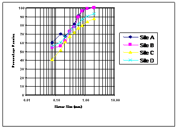
Figure 1.Particle Size Distribution for Site A to D
Table 2 below shows the summary of geotechnical properties of the site A to D respectively. A good X – ray of Table 2 showed that the soil used as backfill was clay of high plasticity (CH) and clay of low plasticity (CL), with liquid limit of 58%, 40%, 35% and 51% respectively. The percentage passing BS Sieve No 20 was 60.10%, 54.30%, 40.7% and 56.2% respectively. This material in question is not a good backfill material because of swelling potential [5]. This means that once water penetrates into the back fill there is tendency for the material to absorb the water and swell. This would definitely increase the active passive (hydrostatic pressure plus earth pressure) against the retaining wall. If the wall was designed in such a way to resist a thrust with relatively small yield, then this is probably the cause of failure of the retaining wall investigated.
Table 2. Geotechnical Characteristic of the Backfill Soil
|
Characteristics |
Quantity |
|||
|
SITE A |
SITE B |
SITE C |
SITE D |
|
|
Liquid limit LL% |
58.12 |
40.04 |
35.09 |
51.23 |
|
Plastic Limit PL% |
34.00 |
25.67 |
19.33 |
25.76 |
|
Plasticity Index PI% |
24.12 |
14.37 |
15.76 |
25.47 |
|
Shrinkage Limit SL% |
22.80 |
18.20 |
16.80 |
19.50 |
|
MDD (Mg/m3) |
1.69 |
1.71 |
1.73 |
1.65 |
|
OMC% |
14.20 |
12.08 |
13.27 |
15.41 |
|
Hydraulic Conductivity m/s |
8.17x 10⁻⁷ |
8.65 x 10⁷ |
1.05x10⁶ |
7.23x10⁷ |
|
% Passing Sieve No 200 |
60.1 |
54.3 |
40.7 |
56.2 |
|
Cohesion (C) KN/m2 |
50 |
38 |
35 |
68 |
|
Angle of Internal Friction (°) |
8 |
10 |
12 |
9 |
|
USCS Classification |
CH |
CL |
CL |
CH |
The amount of yield does not apply to walls that retain backfills of cohesive soil and especially those that retain soil with a high degree of plasticity. In cohesive soils the amount of yield required to give the thrust on a wall is not usually large but because of plastic flow within the clay, the pressure behind the wall continuously tend to increase unless the wall is permitted to yield continuously. The continuous yield, although it is at a slow rate may lead to a large movement over a period of years. Nevertheless, if a wall is capable of withstanding the movement with no undesirable effect it may be designed on the basis of the active pressure. Such a basis of design is common, but the probable life of a wall with a cohesive backfill may be relatively short. A wall that is capable of yielding without detrimental result may be designed on the basis of the active case. However the pressure which will act on such a wall will in general be larger than the active pressure. The pressure distribution diagram may not be triangular even though the wall is designed on the basis of the total active case.
The fact is that any wall must have a margin of safety that is the wall must be capable of staying in place under a thrust some what larger than the active thrust. This margin of strength prevents the wall from reaching the amount of yield required to give active conditions [7].
The factors of safety used in conventional geotechnical practice are based on experience which is logical. However it is common to use the same value of factor of safety for a given type of application, such as long – term slope stability, without regard to the degree of uncertainty involved in its calculation. Through regulation or tradition, the same value of safety factor is often applied to condition that involve widely varying degrees of uncertainty. This is not logical [6].
This brings us to the issues of reliability which provides a means of evaluating the combined effects of uncertainties and a means of distinguishing between conditions where uncertainties are particularly high or low. Reliability theory has not been much used in routine geotechnical practice. There are two reasons for this: first, reliability theory involves terms and concepts that are not familiar to most geotechnical engineers, second, it is commonly perceived that using reliability theory would required more data, time and effort than are available in most circumstances.
Conclusion
A design of retaining wall should be thorough and at least the engineer should appreciate the assumption in the derivation of these formulas used.
A good backfill material should be used with good drainage characteristics to prevent hydrostatic pressure build – up. A situation where it is not available, water should be prevented from getting into the backfill material to prevent a build – up hydrostatic pressure.
The word failure does not necessarily imply catastrophic failure some like a slight sliding of retaining wall should be more aptly described as unsatisfactory performance than a seriously failure.
I hope I have helped you appreciate in general term how challenging is the design and construction of retaining wall. I also hope I have stimulated you to learn about the assumption used in derivation of formulae from theoretical Soil Mechanics used in designing of retaining wall structure.
References
1. BS 1377 .“Method of testing soil for civil engineering purpose”. British Standard Institute ,BSI ,London ,England, 1990.
2. BS 6031 .“Code of Practice for earthwork”. British Standard Institute ,BSI ,London ,England, 1981.
3. Craig, R.F “Soil Mechanics” E and FN SPON 11 New Fetter Lane London 6th edition; pp 5 – 37, 1997.
4. Federal Ministry of Works Nigerian General Specification on Road and Bridgeworks. Federal Government of Nigeria. Lagos, Nigeria, 1970.
5. Michael C. and Stephen P. B. “Correlation of Soil Properties” Pentech Press Limited Graham Lodge, Graham Road London NW4 3DG, 1991.
6. Michael Duncan “Factor of Safety and Reliability in Geotechnical Engineering” Journal of Geotechnical and Geo-environmental Engineering. Pp 307 – 315, 2000.
7. Robert V. W. “Organizing and Evaluating Uncertainty in Geotechnical Engineering” Journal of Geotechnical and Geo-environment Engineering. Pp 583 – 593, 2000.
8. Schroeder “Soils in Construction” John Wiley and Sons Inc. Pp (149 – 165), 1975.