Development of Hot Water Solar Oven for Low Temperature Thermal Processes
Segun R. BELLO and Simon Ogbeche ODEY
Engineering Programme, Federal College of Agriculture Ishiagu, Ebonyi State, Nigeria
Rivers State University of Technology, Obubra Campus, Cross River
E-mail: segemi2002@yahoo.com
Abstract
The most useful form of the Hottel-Whiller-Bliss generalized performance equations for flat plate collector utilizing heat removal factor and loss coefficients is used to model a solar oven- water heating system for low thermal process application. The water heating system was designed, tested and evaluated with a daily collector efficiency of 51.82%, an average daily solar radiation of 689.23 (w/ºc) per day and a useful gain by collector of 563.85 (w/ºc). Loss in collector is 116.39 (w/ºc) and total average daily heat gain by water in collector is 292.26 (w/ºc). Average Daily storage heat capacity of 582.83 (KJ) and the daily convected heat delivered to test chamber is 147.07 (KJ). The overall System efficiency of 25.24% was obtained.
Keyword
Useful gain, storage capacity, collector heat factor, insolation, system efficiency
Introduction
Renewed interest of solar as an energy source in heating systems has gained relevance in various fields and in agricultural operations such as dairy farm hot water supply and food preservation. Microwave heating and food irradiation using solar systems have also been used on commercial scale. Many of these applications require heated air at relatively low temperatures. Traditional heat production is through wood, natural gas or LP gas. Fuel wood account for over 50% of the overall energy consumption in Nigeria, about 80% of these are consumed as firewood mainly in the rural households, [1]. The average daily consumption is 0.5-1kg of dry fuel wood per person, which is equivalent to 10-20 mega joules per day [2]. The current rate of consumption of fuel wood far exceeded the replenishing rate to such extent that acute ecological problems of deforestation soil erosion, and desertification are well recognized problems in the country today [3].
Solar heaters have been used in other operations involving water heating, but interests in heat transfer in oven using water, as heat transfer medium have not been fully investigated. Research investigation has measured the amount of solar energy transmitted by collector and the feasibility of heating ventilating air by passing it though roofing and sidings whose exterior surfaces were painted black.
Okonkwo et al indicated that built in thermal storage solar water space conditioning system could be used efficiently in chick brooding in Nigeria. Their work utilizes a water storage tank constructed with 2mm thick galvanized metal sheet measuring 3m x 1m x 2m insulated with wooden materials, 5cm thick [3]. The behavior of solar dryers is influenced by loading capacity, orientation and angle of inclination [4]. The effect of beam or directional radiation on the collector surface can be maximized when tilted at right angles to the incident beam adding that an inclined surface may receive a significant proportion of its irradiant through reflection from the ground adjacent to it [4]. The works of Mac Craken, Eckhoff Ohos & Shorf and Hansen and Smith as reviewed by [5] reported the use of phase change materials such as salt, dry soil, pond, and a pile of rock for sensible heat storage in collector design.
Water heating constitutes 15% to 25%, or more, of the energy use at home. The approximate annual cost to operate water heaters ranges from $200 for a minimum efficiency gas-fired unit to as much as $500 for a minimum efficiency electric unit [6]. Solar water heaters have been reported to reduce annual operating costs by 50% to 80% using free energy from the sun. As a result of this research activity on the development of thermal solar systems for application in residential housing for the purpose of space heating, a cost effective thermal solar collector with Direct Heat Storage (DHS) was developed [7,8]. When a surface is in contact with a fluid whose bulk temperature is different from the temperature of the surface, a non uniform temperature field is established in the field. This temperature field causes changes in density which may, via buoyant forces cause the fluid to move relative to the surface and heat is transferred in a phenomenon of natural convection [9].
The purpose of this work is primarily to deliver hot water to the storage and made the heat available for heating through convection and radiation mechanisms for space heating purposes in the oven for improved performance for wider applications and to fulfill the majority need of cheap water heating and domestic cooking [10].
Materials and Method
Selection of material of construction is dependent on the properties of the materials that give better performance. The design consisted of a flat plate collector mounted on a stand with variable angle of inclination, a test chamber and a water reservoir mounted on a stand. The units were set out and an insulated water hose used to connect the systems together.
Experimental Procedure
Basic workshop tools were used in the fabrication process and a PRO Level and Angle Finder used in tilt angle graduation on the collector (Fig. 1). Five laboratory thermometers of range -10º to 110ºc were installed on to measure inside and outside temperatures-one at the cold water storage, two installed within the collector; each at the extreme ends of the absorber, in-between the cover and the absorber surface one measures the surface temperature while the other measures the air temperature within the collector-glass space. Another thermometer measures the hot water temperature entering the oven and two others measure the heating chamber temperature. Leakages in the flow line along the tubes in the system were corrected and several tests were run to collect temperature and flow data.
The collector was characterized according to the concrete plates methodology described by [11 and 12]. The collector was exposed to ambient conditions over night. The next morning, the glass cover was cleaned and the thermometers were set up on the collector plate. When the temperature started rising due to increasing incident solar radiation, inlet and outlet water temperatures and ambient air temperatures were read at five-minute intervals.
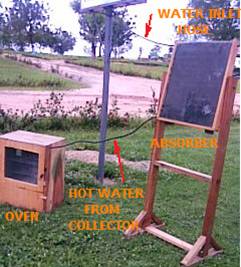
Figure 1. Experimental setup
Design Equations
The design equations of [13, 14, 15] employed by [12] were used in the design. In order to determine the heat transfer along the plate, an assumption of temperature gradient being negligible is taken in the direction of flow. A section through the collector plate–tube configuration is shown in Fig 2.
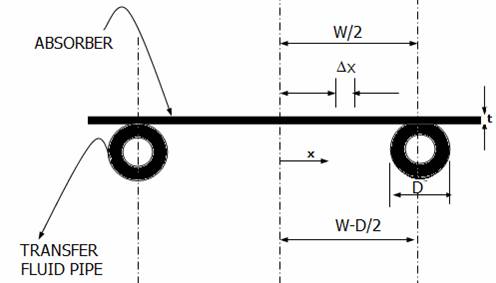
Figure 2. Collector plate – tube configuration
With an assumption of negligible temperature gradient through the metal sheet, and regarding the regions between two tubes as a classified fin problem as shown in Fig. 3, the energy balance between heat absorbed Qin and energy in form of heat released Qout on an elemental surface Dx equal
SDx+UL Dx (Ta-Tx) + (- k ¶T/dx) ½x-(-k¶T/dx)½x+Dx =0 (1)
where S=Absorbed solar energy = useful heat transferred to the fluid (W/M20C)
UL = Rate of energy losses (coefficient from the collector)
Ta= Ambient temperature (ºC)
Tx = Temperature of collector plate (ºC)
K= Thermal conductivity of plate (w/m°C)
¶T=Differential temperature coefficient
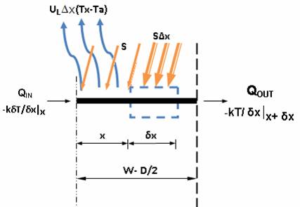
Figure 3. Energy balance on fin element
The two boundary conditions satisfying the equation are the geometrical symmetry at the center line and the known root temperatures ¶T and T given by
¶T|dx=0 = 0, T| x= (w-D)/2 = Tb
where Tb = plate temperature, w = width between two tubes and D=Diameter of tube (m)
If UL/kt = m2 and T – Ta – S/UL = ψ, then
d2 ψ /dx2 - m2 ψ= 0 (2)
This equation has the boundary conditions
¶ψ/dx|x=0 , ψ| x= (w-D)/2 = Tb – Ta– S/UL
The general solution is thus
ψ = C1 Sinh mx + C2 cosh mx (3)
The collector efficiency is determined utilizing the concept of fin efficiency according to [14],
q1fin-base = (W-D) F[S-UL(Tb-Ta)] (4)
where F = tanh m (W-D/2) (5)
m (W-D/2)
Actual total useful energy gain Qu expressed as the product of maximum possible useful energy gain and the collector heat removal factor is evaluated by the relation
Qu = Ac FR [ S-UL (Tf,i – Ta)] w/m2 0c (6)
Collector efficiency for each hour of operation is given by the relation
hhour = Qu = (7)
The main characteristic of energy storage collectors is the high thermal inertia, represented by a high value for the collector time constant [14]. [11] and [16] observed that despite their high thermal inertia, concrete collectors have linear behaviour similar to that in the instantaneous efficiency model
h= a – b [Ťi – Ťamb/ HT] (8)
where Ťi = the mean inlet water temperature, Ťamb = mean ambient temperature, HT = the daily incident radiation on tilted collector surface ,a and b = daily characteristic parameters
Description of System Units
The basic elements of the system consist of the following:
§ Water Reservoir (Storage): Heat transfer medium (fluid) is stored in a container of about 20-25ltr capacity positioned overhead the system such that the hydraulic head is enough to allow flow under gravity through a pipe into the solar collector.
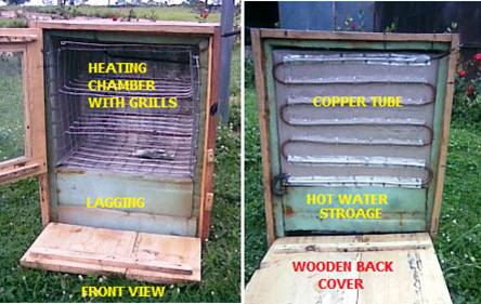
Figure 4. Photograph of the oven showing the front and back view features
§ Solar Collector: The collector absorber is essentially a double sheet of aluminum plate painted black with a mixture of black paint and charcoal. The cover, 4mm thick glass cover is a single window type made of glass separated from the absorber plate by a 2.5cm air space.
§
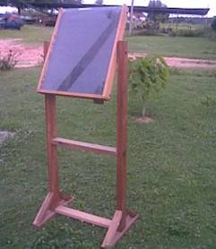
Figure 5. The collector tilted to receive insolation
The fluid pipe is a long copper tube 12.5mm diameter, bent in serpentine form, 50mm between tubes and riveted to the back of the plate with aluminum rivets. The collector casing has a dimension of 680 x 450 x 100mm. The collector is mounted on a support 1.2m above the ground surface and can be titled about an axis to vary the collector inclination to the sun.
Test Chamber: The Test Chamber (heat exchanger) consists of a rectangular aluminum box and copper tube arranged in serpentine form riveted to two of the faces. Hot water from the absorber passes through the copper tube and heat is transferred through conduction to the aluminum box and by radiation the heat is circulated round the box. A see-through glass door is provided in exchanger to be able to monitor temperature in the system.
Results and Discussion
The flow rate required to deliver water to the collector to achieve maximum heat harvest from the collector determined for experimental procedures is M = 0.25l/min and a tilt angle of 50° to the horizontal.
Temperature data were collected at hourly interval of 5 minutes for the hours of sunshine for the days under test. For purpose of analysis temperature profile data were collected per day on clear days (Fig. 6).
Table1. Daily average performance characteristics of the system
|
COLLECTOR |
||
|
Solar Energy Gain I (W/ºC) |
Heat Loss Qloss (W/ºC) |
Heat Gain Qu (W/ºC) |
|
563.81 |
116.39 |
292.26 |
|
STORAGE |
||
|
Storage Heat Capacity, Qs (KJ) |
Heat Convected In Oven, Qconv (KJ) |
Heat Gain In Water, Q Gain, Water (KJ) |
|
712.47 |
186.29 |
526.18 |
Solar radiation data were calculated using solar energy equations. The daily average performance characteristics of the entire system units were tabulated in table1 below
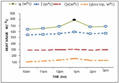
Figure 6. Collector heat gain and losses as a function of time
A plot of collector efficiency and appropriate normalized temperature rise Δt/I (Fig 7) shows the characteristic curve of the energy solar collector. A linear relationship was observed for the collector which is a general characteristic of all flat-plate collectors [4, 12]. The equation for the straight line of best fit representing the daily average characteristic parameters (a and b) were obtained using linear regression analysis is y = 53.982 - 114.61x.
With a correlation coefficient of R2 = 0.73 which is quite high correlated with those of [18] and [4] 0.75 and 0.65 respectively. Also the characteristic curve obtained for the energy storage collector share similar features with those of [12].
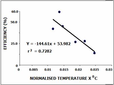
Figure 7. Collector efficiency and normalized temperature rise
The slope of graph in chart 2 is some functions of collector loss, UL and the intercept some function of transmittance–absorptance factor, (τα) e which varies with incident angle to the collector. All efficiencies used for analysis are daily average of efficiencies which indicate a collector efficiency of 51.82% at an average solar radiation, (qt) of 689.23 W/°c and useful heat gain of 563.85 w/ºc. Energy distribution within the system indicates a uniform distribution with minimal heat loss in the collector, 116.39 (W/°c), the average heat gain by water in collector is delivered to the storage at a daily average of 582.83 (KJ) in the oven.
The total average daily heat gain by water in collector is 292.26 (W/°c) and a daily convected heat of 147.07 (KJ was delivered to test chamber at 50.32% efficiency. The overall system efficiency is 25.24%. A comparison of daily solar radiation available and energy gained in the collector, the storage tank and the test chamber are shown in charts 3 and 4. Due to high thermal inertia, in the early morning hours the air loses heat from the storage collector (negative instantaneous efficiency) thus, to construct the daily efficiency curve, Equation (8) was used with the data after the time at which the instantaneous efficiency become positive.
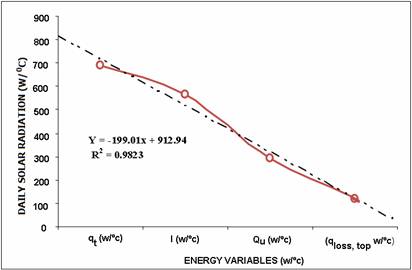
Figure 8. Daily available solar radiation and energy gain for the collector
The daily total available energy at the collector is not entirely converted to the energy gain in the collector but some were dissipated as losses (qloss,, top etc) and others retained on the surface. Energy available in storage is dissipated through convection to the heating chamber while the rest is loss through the fluid.
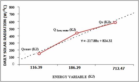
Figure 9. Comparison of energy available in storage, water and test chamber
Hot Water Storage: Energy storage is in the form of sensible heat from a liquid medium. The relationship between the average collector temperature and the temperature at which heat is delivered into the storage shows that the temperature of the collector, which determines the useful gain, is higher than the temperature at which the heat is finally used. These temperature drops were minimized by adequate insulation. The advantage of this unit in drying process is the capacity to avoid temperature peaks during the day and the capacity to continue transferring heat even if the solar radiation incidence ends.
Conclusion
A solar water heating system has been designed and constructed. Performance evaluation carried out indicates an overall system efficiency of 25.98% and absorber temperature of 72ºc. Efficiency of collector varies with water flow rates. As the water flow rate is increases the operating temperature decreases and heat gain by water reduced.
The collector is more efficient at low radiations; 52.85% at 630.08 w/m2 and 51.00% at 739.40w/m2. This is obvious at lower operating temperatures for collectors Solar radiation, heat gain and collector temperature are highest between 1300hr and 1400hrs because of the collector tilt angle (optimum tilt angle=50º) causing a larger percentage of incoming radiation to be incident on the collector.
The system is efficient to be used for low temperature processes as pasteurization and also can be adapted for use in incubation. It can also found use in domestic hot water requirements. The amount of energy made available in the chamber through convection is low which is indicative of low overall system efficiency. The heat delivered to the storage at a daily average of 582.83 (KJ) is considerably higher than the convected heat in the oven which is the actual heat available for low temperature technological heat processes. This indicates that more heat is retained in water in storage than those delivered into the oven and thus accounted for the low overall system efficiency.
An increase in the collector surface area, adequate lagging of the heat pipes, control of flow in pipe network within the heat exchanger and review of the bonding material to increase the surface area of contact of pipe with the aluminum casing to increase the temperature gradient in the classical fin element approach assumed such that more heat will be conducted and subsequently be radiated into the oven. Further research in these areas is currently being addressed.
References
1. Iwu, 1998
2. Anderson D. and Ahmed K., The Case for Solar Energy Investment. Technical paper NO 279 Industry and Energy Department, World Bank ,Pp 9-16, 1995
3. Okonkwo W.I and Akubuo C.O. Thermal Analysis and evaluation of heat requirement of a passive solar energy poultry chick Brooder. Proceedings of NIAE Vol.23, pp 373, 2001
4. Chau K.V Optimum Tilt Angles for Solar Collectors in Clear Sky Conditions. J. Agric Res. Vol.28 Pg 321-328, 1982.
5. Budyko M.I., The heat balance of the earth surface. United States Department for Commerce and Weather Bureau, Washington D.C. p28, 1978.
6. EPA, Improve energy efficiency with solar water heating. United States Environmental Protection Agency report, September 2001.
7. Kazimierz Szymocha. Advanced thermal solar system with heat storage for residential house space heating. Paper presented at SESCI 2005 Conference, British Columbia Institute of Technology, Burnaby, British Columbia, Canada August 20 - 24, 2005.
8. Witter, Volker, Global Trends in Solar Thermal Technology. Proceedings of 2nd European Solar Thermal Energy Conference, ESTESC 2005, Freiburg, Germany June 21-22, p. 16-25, 2005.
9. Faud R.M and Kerswani K.K Combined Natural and forced convention Heat transfer from Horizontal cylinders to water5 .Int. J. Heat mass transfer. Vol. 6 pp 1175-1191, 1973.
10. ASAE Standards. Testing and Reporting Solar Cooker Performance. ASAE S580 Jan 2003.
11. Nayak, J.K., Sukhatme, S.P. Limaye, R.G. amd Boshetty, S.V., Performance studies on solar concrete collectors, Solar energy, Vol 42, No. 01. Pp 45-56, 1989.
12. Santos B.M. Queiroz M. R. and Borges, 2005. A solar collector design procedure for crop drying. Brazilian journal of chemical engineering. Vol. 22. No. 02 pp. 277-284, April-June, 2005.
13. Duffie, J. A and Beckman, W.A., Solar collectors in clear sky conditions J. agric res. Vol. 28, pp 321-328. 1976.
14. Duffie, J. A., Beckman, W. A. Solar Engineering of Thermal Process, 2nd ed., New York, John Wiley,1991
15. Meinel A.B. and Marjorie P. Meinel, Applied Solar Energy- an introduction. Addison Wesley publishing company inc. NY 1976.
16. Boppshetty et al, 1992.
17. Russell B. Brinsfield, Kenneth E. Felton, Utilization of solar Energy in Broiler production Trans. of ASAE, 1532-1537. 1980