Simulation Studies of Shear Stresses in Reinforced and Non-Reinforced Concrete Structures
1*Akindehinde Ayotunde AKINDAHUNSI; 2John. Ade AJAYI and 3Oluleke OLUWOLE
1*Civil Engineering Dept., Obafemi Awolowo University, Ile-Ife, Nigeria
2Metallurgical and Materials Engineering Dept, Federal University of Technology, Akure, Nigeria
3Mechanical Engineering Dept., University of Ibadan, Ibadan, Nigeria
E-mails: akinakin@oauife.edu.ng or aakindahunsi@ymail.com; johnadeajayi@yahoo.com; lekeoluwole@yahoo.co.uk
Abstract
A simulation study of the effect of shear stresses in non-reinforced and reinforced structures was carried in this work. Using the Finite Element Method and equations of elasticity, columns and concrete deck of a simple storey structure were subjected to plane strain conditions. The results showed that proper reinforcement causes stresses to be directed into the reinforcements with the resultant shear stresses in the steel reinforcements far below the yield stresses of the steels. In non-reinforced and insufficiently reinforced members it was observed that stresses were directed into the concrete itself with resultant transverse shear at critical joints of the structure. In the insufficiently reinforced member, the resultant shear of the concrete resulted in load transferred to the reinforcement itself with the resultant buckling of reinforcement and eventual collapse of structure.
Keywords
Concrete, Reinforcement, Stresses, Finite Element modelling
Introduction
Husem and Pul [1], defined concrete used in engineering structures as a composite material produced using cement, aggregate, water and chemical and mineral admixture materials when necessary. Reinforced concrete (RC) is one of the most important building materials and is widely used in many types of engineering structures.
Economy, efficiency, strength and rigidity of reinforced concrete make it an attractive material for a wide range of structural applications. The ultimate objective of the designer is to create a structure that is safe and economical. The safety and serviceability assessment of the structures necessitate the development of accurate and reliable methods and models for their analysis. The rise in cost of materials used in structures and labour costs encourage engineers to seek more economical alternative designs often resorting to innovative construction methods but without lowering the safety of the structure. In addition, the extent and impact of disaster in terms of human and economical loss in the event of structural failure prompt designers to check the design thoroughly [2].
The strength and durability of concrete has undergone continuous improvement over the years and these improved materials are now commonly used concrete is characterized by excellent load carrying behaviour in compression but also by brittle failure in tension. The main reason for adding steel fibres are to improve the tensile behaviour and to obtain a ductile material in tension [3]. For the analysis and design of reinforced concrete structures it is required to define the shape of stress strain behaviour of steel reinforcement. There are a number of stress-strain relationships available to idealize the steel. The elastic perfectly plastic model is widely used for idealization of reinforcing steel. Modelling is one of the most important areas for finite element analysis.
Accuracy in the modelling of geometry, loads, material properties, boundary conditions, and other structural properties are of absolute necessity for close numerical idealisation of the actual member/structure [4]. Feenstrat and Borsts [5] opined that the proper modelling of tension - compression stress states in plain and reinforced concrete is an outstanding issue in finite element analysis of concrete structures that is of utmost practical importance to the designer and very challenging at the same time. Incidences of building collapse is assuming alarming rate in Nigeria that up till now neither the government nor the professional bodies have been able to effectively come out with a definite solution to the problem. Major cause of this is the build-up of stresses and especially due to shear in the structure. Proper design, the use of materials with adequate strength and standard and good supervision are the panacea to this problem. This paper examined the effect of shear stresses in reinforced and non-reinforced concrete structures.
Methodology
The material was considered isotropic and two dimensional. The material was subjected to volume loading in the y-direction by the concrete floor, columns and the roof. The values of the loads applied are: - Values of stress applied by roof = volume force applied by roof in y direction given as 10 N/mm2.Volume force in columns and concrete flooring = 500 N/mm2.
The Matlab pdetool graphics user interface [6] was used in the finite element modelling of the material. Three-node triangular elements were used in meshing and the finite element equation applied to the elements. Concrete is a quasi-brittle material and has different behaviour in compression and tension. The elastic property is characterized mathematically by certain functional relationships connecting forces and deformations. Sokolnikoff [7], stated that the elastic property of material media is shared by all substances provided that the deformations do not exceed certain limits determined by the constitutive characteristics of the body.
Derivation of the elemental finite element equation is as follows:
Consider a free body diagram of an infinitesimal element shown in
Figure1 below:![]()
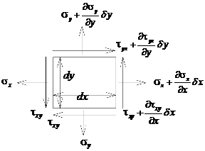
Figure 1. Forces acting on a 2-Dimensional infinitesimal elemental body
Equilibrium of forces yields,
![]() (1)
(1)
and
![]() (2)
(2)
![]() ,
,![]() are body force/unit area or per unit
volume assuming unit thickness
are body force/unit area or per unit
volume assuming unit thickness
Thus, simplifying equations (1) and (2),
![]() (3)
(3)
and
![]() (4)
(4)
Therefore, the constitutive equation is:
![]() (5)
(5)
where, ![]() (6)
(6)
![]() (7)
(7)
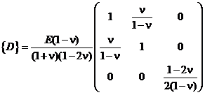 for plane strain condition (8)
![]() Elastic modulus and Poisson’s ratio
respectively
Elastic modulus and Poisson’s ratio
respectively
The kinematic equations relating strain to displacements are
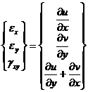 (9)
(9)
Where ![]() and
and ![]() are displacement in the x and
y directions respectively
are displacement in the x and
y directions respectively
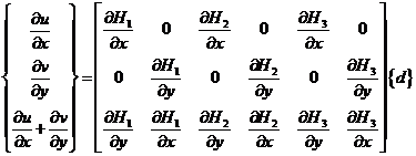
Combining (3), (4), (5) and (9) has 8 unknowns ( 3 stresses, 3 strains and 2 displacements) for 8 equations (2 equilibrium, 3 constitutive and 3 kinematic)
The displacement can be expressed as
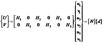 (10)
(10)
where ![]() is the nodal displacement vector.
is the nodal displacement vector.
which results in
 (11)
(11)
Thus: 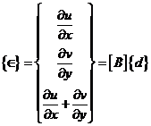 (12)
(12)
Thus;![]() (13)
(13)
` 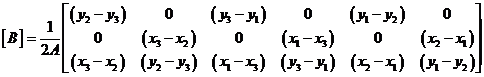 (14)
(14)
Results and Discussion
Results
The results of the simulation study are as presented in Figures 1 to 24 of the appendix. Figure 1 showed a framed storey concrete structure that is not properly reinforced. Finite element meshing of the structure is as presented in Figure 2. Figure 3 represents the displacement of not properly reinforced structure in the x-direction; the value of the result generated indicated that value ranged between -9.8 x 10⁻⁵ to 6. x 10-5 mm. The displacement in the y-direction in Figure 4 of the same structure gave a value of -0.1 x 10⁻⁴ to 5.5 x 10⁻⁴ mm. Figure 5 indicated strain in the x-direction and it gave a value ranging between -5.8 x 10⁻³ to 3.2 x 10⁻³. The value of strain in y-direction for structure in Figure 6 is given in Figure 6 as -0.015 to 0.017mm. Figure 7 gives the value of shear stress for the same structure to be -6.8 to 8.6 N/mm2 while the value of shear strain shown in Figure 8 is given in the range of -0.015 to 0.014 N/mm2.
Figure 9 presents displacement of the non reinforced concrete structure in x-direction, the value is given in the range of – 10 x 10-5 to 7.2 10-5mm, while its displacement in the y-direction is in the range of 0 to 6.4 x 10⁻⁴ mm as shown in Figure 10. The value of strain in the x-direction for the same structure from Figure 11 ranges from -6 10-3 to 18 10-3 mm, while strain in the y-direction as indicated from Figure 12 is between -0.05 to 0.024 mm. Figure 13 is a representation of stress in the x-direction of the non reinforced structure, the values generated as a result of this stress ranges from -16 to 12 N/mm2, while stress in the y-direction is presented in Figure 14 and the value is between -54 to 28 N/mm2. Shear stress for the same structure is as shown in Figure 15; indicated value is from -27 to 22.5 N/mm2, while shear strain (Fig.16) gave a value of between -0.035 to 0.031mm.
For the properly reinforced concrete structure, displacement in x-direction is shown in Figure 17, and its value is between -5 x 10⁻⁵ to 6.4 x 10⁻⁵mm, the value given as 0 to 5.5 x 10⁻⁴ mm for displacement in y-direction is presented in Figure 18. Figure 19 represents strain in x-direction and the value ranged between -5 to 5.6 x 10⁻³mm, while the value of strain in the y-direction is between -0.025 to 0.027mm as indicated in Figure 20. For the same structure, Figure 21 showed the value of stress in the x-direction ranges between -15 to 10 N/mm2 and the value of stress in the y-direction is between -33 to 33 N/mm2 as presented in Figure 22. Shear stress is represented in Figure 23 and the value is given as -18 to 18 N/mm2 while value of shear strain component of the structure is shown in Figure 24 as -0.024 to 0.025 mm.
Discussion
Figure 3 presents the displacement of not properly reinforced structure in the x-direction, the result generated indicated that value ranged between -9.8 x 10⁻⁵ –to 6.3 x 10⁻⁵ mm while Figure 9 represents displacement of the non reinforced concrete structure in x-direction, the value is given in the range of – 10 x 10-5 to 7.2 x 10⁻⁵ mm. The displacement of the properly reinforced concrete structure in x-direction is shown in Figure 17, and its value is between -5 x 10⁻⁵ to 6.4 x 10⁻⁵ mm. It could be seen from the results of the displacements these structures that the structure that is properly reinforced has the lowest value for displacement followed by the one that is not properly reinforced and the last being the structure without reinforcement. This portends the significance of proper reinforcement on structures as it resists unnecessary movement of structure as much as possible.
The displacement in the y- direction in Figure 4 of the same structure gave a value of -0.1 x 10⁻⁴ to 5.5 x 10⁻⁴ mm for non properly reinforced structure, that of non reinforced structure in the y-direction is in the range of 0 to 6.4 x 10⁻⁴mm as shown in Figure 10 and for properly reinforced concrete the value given as 0 to 5.5 x 10⁻⁴ mm for displacement in y-direction is presented in Figure 18. Meshing of the structures showed a concentration forces at the joints in Figures 4 and 10, however, Figure 18 for properly reinforced concrete present a different scenario in which much of the forces were concentrated on the left side of the wall, this accounted for the values obtained.
Figure 5 indicated strain in the x- direction and it gave a value ranging between -5.8 x 10⁻³ to 3.2 x 10⁻³ for not properly reinforced concrete and a concentration of strain in the middle slab and joints. The value of strain in the x-direction for the non reinforced structure from Figure 11 ranges from -6 x 10⁻³ to 18 x 10-3, concentration of it was only at the middle joints, however, Figure 19 represents strain in x-direction and the value ranged between -5 to 5.6 x 10⁻³ for properly reinforced structure and the concentration of strains were at the middle and top joints.
The value of strain in y-direction for insufficiently reinforced structure is given in Figure 6 as -0.015 to 0.017 mm and this is concentrated at the middle slab with perches of strain on the wall while the value of strain in the y-direction for non reinforced structure as indicated from Figure 12 is between -0.05 to 0.024 mm and this is seen at the middle joints with projections into the slab, the value of strain in the y-direction is between -5 x10⁻³ to 5.6 x10⁻³ mm as indicated in Figure 19 for properly reinforced structure, this shows that structure in Figure 20 with a value of -0.025 to 0.027 mm can undergo more strain when compared to the other two.
Figure 13 showed stress generated in x-direction for the non reinforced structure with -16 to 12 N/mm2 as the value obtained and Figure 21 gave a value of -12 to 10.1 N/mm2 for stress generated in the same direction for properly reinforced structure. This indicated that well reinforced structure can take absorb more stress than structure without reinforcement or not properly reinforced.
For stress in y-direction non reinforced structure in Figure 14 has a value of -56 to 25 N/mm2 while properly reinforced structure in Figure 22 in the same direction has a value of -38 to 30 N/mm2. This demonstrates reinforced structures ability to absorb a lot of negative stresses.
Figure7 gives the value of shear stress for not properly reinforced structure to be -9.2 to 8.4 N/mm2, Figure 15 is a representation of shear stress of non reinforced structure, the values generated as a result of this stress ranges from –24.8 to 22.5 N/mm2, while values of that of properly reinforced concrete is in the range of -17 to 18 N/mm2 as shown in Figure 23. It is observed from Figure 7 that the direction of stresses generated is into the unreinforced part of the wall structure from the joints while the reinforced portion remained virtually free from stresses, for non reinforced structure in Figure 16, stresses are developed at the upper part of the walls joints, while in Figure 23 shear stress developed all through the upper reinforced section of the wall. This demonstrates the ability of reinforcement to properly transfer all stresses through the walls instead of being concentrated at the joints which can lead to sudden shear failure.
Shear strain as a result of shear stress in Figure 8 for not properly reinforced structure gave values ranging from -0.012 to 0.011 mm, that of non-reinforced structure is shown in Figure 16 as -0.036 to 0.031 while Figure 24 gave values in the range of -0.025 to 0.026 mm for properly reinforced structure. The area of influence of strain followed the same trend with that of shear stress.
Conclusion
i. From Figures 3, 9 and 17, it is obvious that properly reinforced concrete absorb stresses thus restrict displacement of structure. Same scenario is presented in Figures 4, 10 and 18.
ii. Stresses generated on both x and y axes for non reinforced structure are large as indicated in Figures 13 and 14, when compared to values generated for properly reinforced structure in Figures 21 and 22. This buttress the fact that reinforcement in concrete had absorbed much of the stresses.
iii. Shear stress indicated in Figure 7 started from the middle joints and projected into the walls of not properly reinforced structure and same thing is replicated in Figure 15 for unreinforced structure, however, this is at variance with the situation in Figure 23 for properly reinforced structure in that the stresses were evenly distributed on both sides of the upper walls. Figures 7 and 15 are examples of heavy concentration of stresses at the joint and this can lead to sudden joint failure.
iv. The result of shear strain in Figures 8, 16 and 24 developed because of shear stress which follows same pattern as that of shear stress, it follows that for Figures 8 and 16 more of the strains would be developed at the joints which would not augur well of the structures because it would exert undue pressure on the joints.
v. From this work it has been shown that improper reinforcement cause critical stresses to build up at joints of a structure that would result in sudden collapse of such structure.
References
1. Husem, M and Pul, S. Investigation of Stress–Strain Models for Confined High Strength Concrete. Sadhana Vol. 32, Part 3, pp. 243–252, 2007
2. Siddique, M. A and Abdur Rouf, M. D. Effect of Material Properties on behavior of over-Reinforced Concrete Beams. Asian Journal of Civil Engineering (Building And Housing) Vol. 7, No. 2 Pages 195-204, 2006.
3. Thomée, B_, Schikora, K and Bletzinger, K. U, Material Modeling of Steel fiber Reinforced Concrete. EUROMECH Colloquium 460 Numerical Modelling of Concrete Cracking Innsbruck, Austria, 2005.
4. Das, S and Hadi, M. N. S.Non-Linear Finite Element Analysis of Reinforced Concrete members using Msc/Nastran. MSC World Users’ Conference, 1996.
5. Feenstrat, P. H and Rene De Borsts A Composite Plasticity Model For
Concrete. International Journal of Solids Structures Vol. 33, No. 5, pp. 707-730, 1996
6. Matlab pdetool graphics user interface, 2006
7. Sokolnikoff, I. S. Mathematical Theory of Elasticity. McGraw-Hill
Book Company, Inc. New York. 1956.
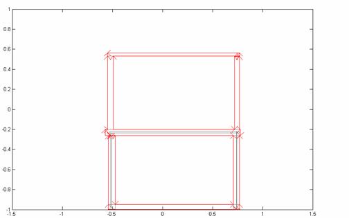
Fig.1. Storey structure with insufficient reinforcements on lower columns and
concrete deck
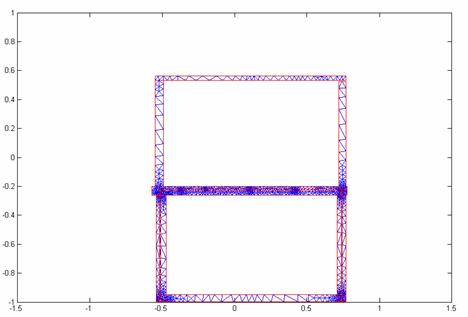
Fig. 2. Meshing of the insufficiently reinforced storey structure
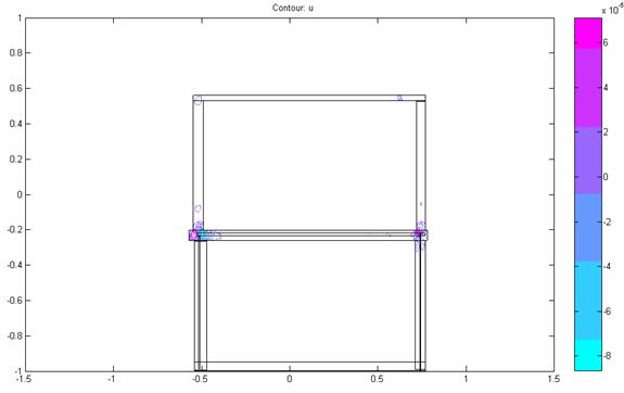
Fig. 3. Displacement in the x-direction for insufficiently reinforced structure
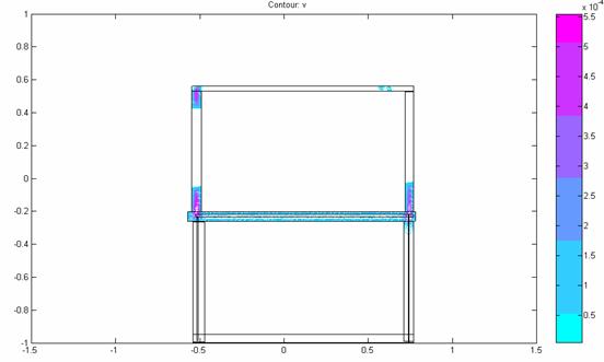
Fig. 4. Displacement in the y-direction for insufficiently reinforced structure
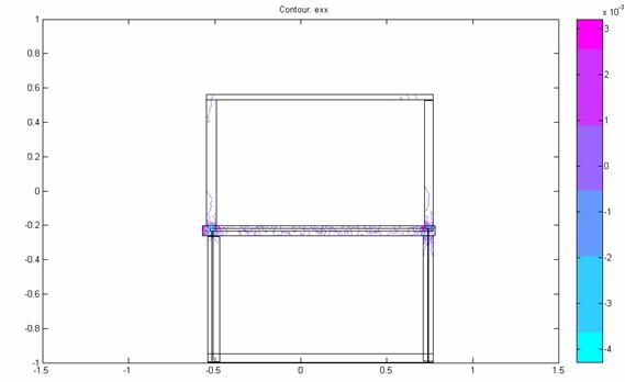
Fig.5. Strain in the x-direction for insufficiently reinforced structure
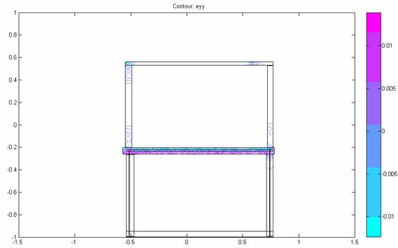
Fig. 6. Strain in the y-direction for insufficiently reinforced structure
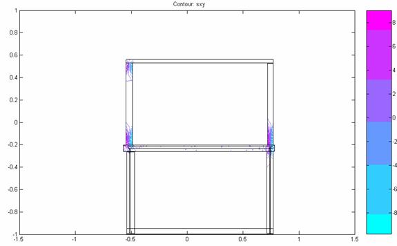
Fig.7. Shear stress for insufficiently reinforced structure
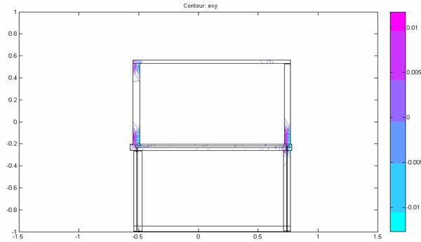
Fig.8. Shear strain for insufficiently reinforced structure
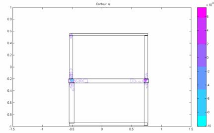
Fig.9. Displacement in the x-direction for non-reinforced structure
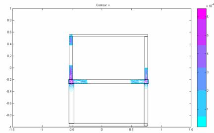
Fig.10. Displacement in the y-direction for non- reinforced structure
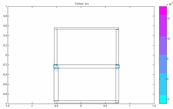
Fig.11. Strain in the x-direction for non-reinforced structure
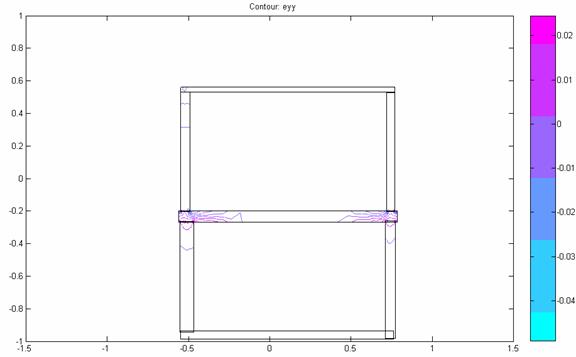
Fig.12. Strain in the x-direction for non- reinforced structure
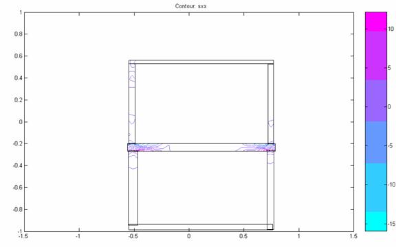
Fig.13. Stress in the x-direction for non- reinforced structure
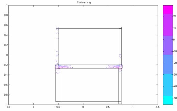
Fig.14. Stress in the y-direction for non- reinforced structure
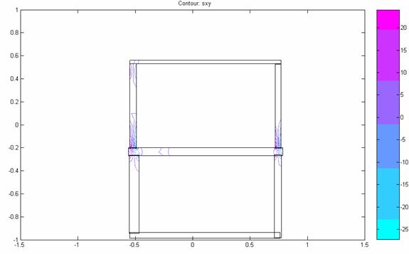
Fig.15. Shear stress for non- reinforced structure
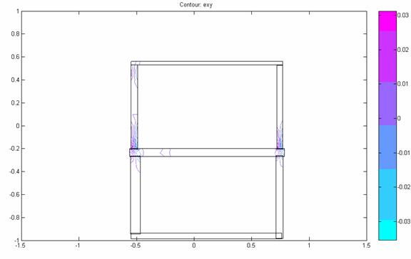
Fig.16. Shear strain for non- reinforced structure
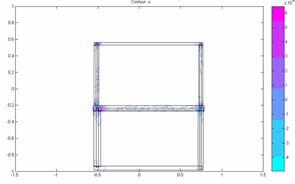
Fig.17. Displacement in the x-direction for properly reinforced structure
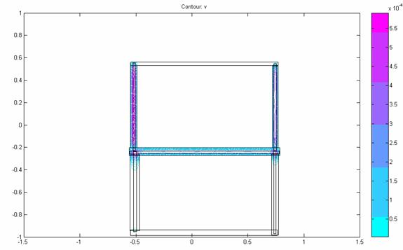
Fig.18. Displacement in the y-direction for properly reinforced structure
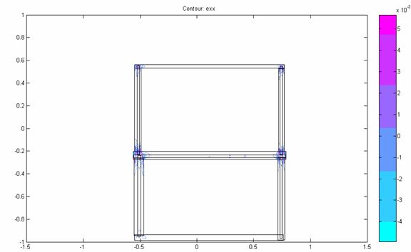
Fig.19. Strain in the x-direction for properly reinforced structure
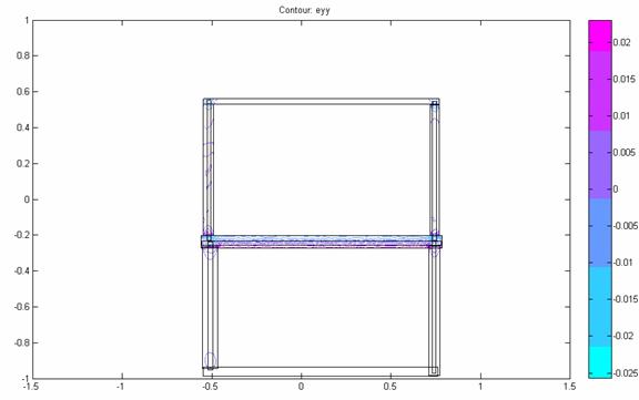
Fig. 20. Strain in the y direction for properly reinforced structure
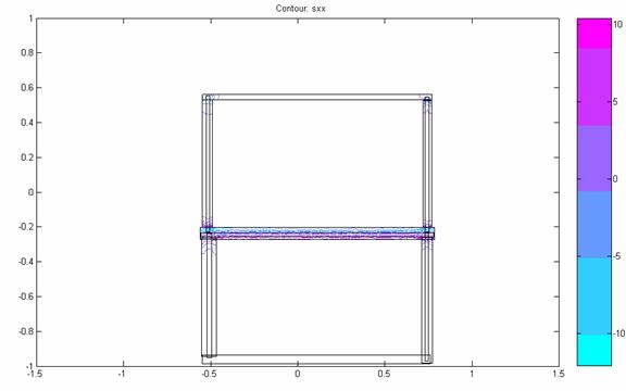
Fig.21. Stress in the x-direction for properly reinforced structure
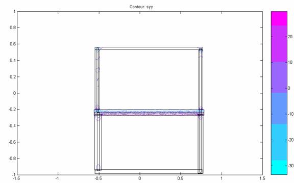
Fig.22. Stress in the y-direction for properly reinforced structure
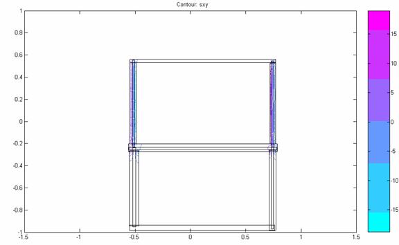
Fig.23. Shear stress for properly reinforced structure
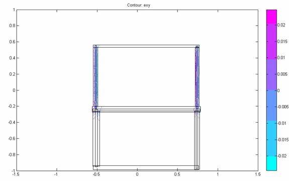
Fig. 24. Shear strain for properly reinforced structure