Optimal Design of TCR/FC in Electric Arc Furnaces for Power Quality Improvement in Power Systems
Rahmat Allah HOOSHMAND* and Mahdi TORABIAN ESFAHANI
Department of Electrical Engineering, University of Isfahan, Hezar-Jerib St.,
Postal Code: 8174673441, Isfahan, Iran.
E-mail: hooshmand_r@eng.ui.ac.ir; torabian_mehdi@yahoo.com
(* Corresponding author)
Abstract
Electric Arc Furnaces (EAFs) are unbalanced, nonlinear and time varying loads, which can cause many problems in the power system quality. As the use of arc furnace loads increases in industry, the importance of the power quality problems also increase. So in order to optimize the usages of electric power in EAFs, it is necessary to minimize the effects of arc furnace loads on power quality in power systems as much as possible. Therefore, in this paper, design and simulation of an electric plant supplying an arc furnace is considered. For this purpose, a three phase arc furnace model, which can simulate all the mentioned power quality indices, is developed based on Hyperbolic -Exponential model (V-I model). Then by considering the high changes of reactive power and voltage flicker of nonlinear furnace load, a thyristor controlled reactor compensation with fixed capacitor (TCR/FC) are designed and simulated. In this procedure, the reactive power is measured so that maximum speed and accuracy are achieved. Finally, simulation results verify the accuracy of the load modelling and show the effectiveness of the proposed TCR/FC model for reactive compensating of the EAF.
Keywords
Electric Arc Furnaces; Power Quality; Harmonic Analysis; Voltage Flicker; TCR/FC Compensation.
Introduction
The EAFs are among the largest electrical loads in power systems. Regarding the fast and heavy deviations of electric power in these loads, the bus voltage of these furnaces is unbalanced and has large oscillations. Moreover, the EAFs cause deteriorating of the power quality, making voltage flicker, unbalancing in voltage and current, and occurring odd and even harmonics in power systems. In order to study in this field and improve the above mentioned factors, exact and complete design of the power system with arc furnaces should be performed.
Therefore it is necessary to find a suitable model for electrical arc furnaces. In this regard, numerous models have been presented to describe the electric arc [1-10]. Some of these models are based on voltage-current characteristic (VIC) method [1-3]. This kind of model is simple and direct and it can satisfy a certain operating condition, and the simplification of VIC is the main factor of accuracy. Harmonic voltage source method in [4-5] is based on the harmonic study of a certain kind of the arc voltage waveform. The problem is that under this voltage waveform, the arc furnace system doesn't operate at the maximum power transfer condition.
Another group of models is based on the frequency domain that is often used for harmonic analysis of the system [6-7]. The frequency domain solution of nonlinear differential equations depends on the system topology and the operating condition. Some of the other models are based on stochastic characteristics of the EAF which are mainly suitable for voltage flicker analysis [8-9]. Another method for analyzing the arc model in time domain is based on the Cassi-Mayer equation [10]. In this method, Cassi and Mayer equations are used in the cases of the low and high current of the arc, respectively. In these methods, there are some restrictions such as requiring the initial conditions for solving the differential equations.
On the other hand, in relation to using the TCR/FC compensators for reactive power compensating, a limited researches have been done [11-17]. In this regard, in [11-14], only the TCR compensators analysis and its dynamic investigations have been performed, and nothing has been mentioned about its control. Also the operation mechanisms of the TCR and STATCOM in reducing flicker of the EAF have been compared in [15-17]. In [18, 19], the various methods of reactive power measurement in power system including the EAF have been investigated. The measuring method in this reference is based on instantaneous measurement of reactive power for compensating system and the harmonics effects on the system output has not been explained.
Regarding the problems of the EAF modelling, in this paper, the optimal design for modelling of the furnace load is presented in the next section. This model is considered based on exponential-hyperbolic form which causes many problems in the power system quality. Also the model can describe different operations of the EAF and it does not need specific initial conditions. Then, by considering this model, an optimal TCR/FC compensator for reactive power compensation and power quality improvement is designed. In this design, instead of using fixed capacitors, the LC filters are used. For this purpose, a real system has been taken by considering the obtained amounts extracted from Mobarekeh Steel Company (located in Isfahan-Iran). Finally, the results and discussions show that the TCR/FC can compensate the reactive power of the EAF and improve the power quality indices in power system.
The Model of Power System with Ac Electric Arc Furnace
The electric diagram of a source supplying an EAF is illustrated in Figure 1. In this figure, bus 1 is the point of common coupling (PCC) which is the supplying bus of the EAF transformer. In order to change the input active power of the EAF, transformer TF, (MV/LV) is used. This transformer is equipped with a tap changer located at the secondary winding to have the ability of changing the voltage of the furnace. The arc furnace is also connected to the PCC through the transformer TS, (HV/MV). In this figure, XC and RC are the reactance and resistance of the connecting cable line to the furnace electrodes, respectively. Also, XL,sc is the short circuit reactance at bus PCC.

Figure 1. Diagram of an EAF connected to the rest of power system
In order to investigate the power quality aspects in power systems including the EAF, it is necessary to design a suitable model which represents the behaviour of the EAF in all of the operating conditions. For this purpose, the electric arc is modelled by the following equations:
|
|
(1) |

where V and i are arc voltage and current of the EAF,
respectively. Also Vat is the voltage threshold magnitude to
which voltage approaches as current increases. Furthermore, ![]() is
the current time constant in kA. It should be noted that the voltage Vat
depends on the arc length. The constants C and D are
corresponding to the arc power and arc current, respectively. These constants
can take different values which depend on the sign of the derivative of the arc
current. Since equation (1) has a behavior similar to exponential and hyperbolic
functions, it is called exponential- hyperbolic model. There are two paths to
increase or decrease the current. The first path is related to the increasing
state of the current and the second path is associated with decreasing state of
the current. In this regard, the constants C and D are classified
into two groups. The constants for the first group (or first path) are Ca
and Da. Also constants of the second group (or second path)
are Cb and Db.
is
the current time constant in kA. It should be noted that the voltage Vat
depends on the arc length. The constants C and D are
corresponding to the arc power and arc current, respectively. These constants
can take different values which depend on the sign of the derivative of the arc
current. Since equation (1) has a behavior similar to exponential and hyperbolic
functions, it is called exponential- hyperbolic model. There are two paths to
increase or decrease the current. The first path is related to the increasing
state of the current and the second path is associated with decreasing state of
the current. In this regard, the constants C and D are classified
into two groups. The constants for the first group (or first path) are Ca
and Da. Also constants of the second group (or second path)
are Cb and Db.
As it can be seen in equation (1), for the positive current and regarding the hysterias property of the arc, there are two cases. In the increasing current case, the hyperbolic equation and in the decreasing current case exponential equation is used. Hence, this model is called exponential-hyperbolic model. The proposed method has the capability of describing the EAF behaviour in time domain using differential equation. In addition, it is able to analyze the behaviours in the frequency domain without solving the sophisticated differential equations. Moreover, the proposed model can describe different operating conditions of the EAF such as initial melting (scrap stage), mild melting (platting stage) and refinement of the EAF. The results match with actual conditions of the EAF in the steel industries [9].
Investigation of Voltage Flicker and Unbalanced Situation in the EAF
To study the effect of voltage flicker on the systems
with the EAF, it is sufficient to consider the time-variant form of ![]() in equation
(1). For this purpose, the voltage
in equation
(1). For this purpose, the voltage ![]() for different phases with the voltage
flicker can be writen as:
for different phases with the voltage
flicker can be writen as:
|
|
(2) |

where F(t) is the flicker function, Vatj(j=1,2,3) are three phase voltages of the furnace load, Vat0j(j=1,2,3) are constant values of the voltages and kj(j=1,2,3) indicates the flicker intensity in different phases.
In this paper, the effect of two types of flicker on the dynamic characteristic of the electric arc is studied. In the first type, the function F(t) will be considered in the form of a sinusoidal voltage flicker, as:
|
F(t) = sinωft |
(3) |
where ωf is the flicker frequency. So, in the same way, the effective values of voltage and current of the EAF will be changed also by the frequency of the flickering frequency (ωf).
In the second type, the function F(t) is chosen so that it varies randomly. In this regard, the F(t) is modulated with a random signal in the different phases. This signal has the mean of zero with the frequency spectrum in the range of 4-14 Hz. Therefore,
|
F(t) = N(t) |
(4) |
where N(t) is a band limited white noise with zero mean and variance of 1.
In order to investigate the effect of unbalanced situation on the proposed exponential-hyperbolic model of load of the EAF, different values for the voltage Vat in equation (1) for different phases are considered. To study the effect of even harmonics which are produced in the early stage of the charging the furnace, different values of Vat are considered for positive and negative part of each phase current.
Optimal Design of TCR/FC compensators
In order to compensate reactive power and voltage flicker improvement in power system including the EAF and on the basis of Figure 1, in this section, an optimal design of TCR compensator along with a parallel capacitor will be presented. The on-line diagram of this structure is illustrated in Figure 2. So, firstly, the operation of compensator is discussed and analyzed completely, and then the optimal design procedure and its control will be explained. Also, the process of parallel capacitors design in the system is presented.
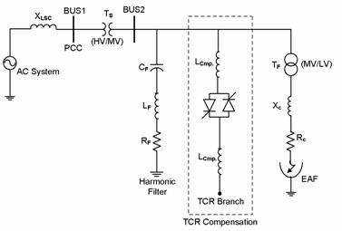
Figure 2. Configuration of a TCR/FC connected to an EAF
Operational Mechanism of the TCR/FC
As it can be seen in Figure 2, the effective inductance of the TCR compensator can be varied by changing the firing angle of the thyristors. If the thyristors are fired exactly at the voltage peak of the supply, then they will conduct perfectly. The TCR current is essentially reactive with almost 90 degrees lag phase. The instantaneous current of the TCR for half cycle can be written as follows [18]:
|
|
(5) |

where V is the effective voltage and XL is reactance of the TCR. Also, α and σ are the firing angle and the conducting angle of thyristors of TCR, respectively. Fundamental component (1st harmonic) of this current will be obtained by Fourier analysis as follows:
|
|
(6) |
It should be mentioned that the relation of ![]() and
and ![]() is given as
follows:
is given as
follows:
|
α + σ/2 = π |
(7) |
As it can be seen in equation (6), the magnitude of the first harmonic of the current can be written by:
|
I1 = BL(σ)V |
(8) |
In this equation, ![]() is the susceptance of the basic
frequency which can be regulated and will be controlled by conducting angle as:
is the susceptance of the basic
frequency which can be regulated and will be controlled by conducting angle as:
|
|
(9) |
where the maximum value of BL will be obtained in conducting angle 180o (or complete conducting angle of the thyristor) as follows:
|
(BL)max = 1/XL |
(10) |
Also the minimum value of BL is zero which is obtained in zero conducting angles.
Paying attention to the above mentioned topics, for generating the reactive power in power system, the parallel capacitors with TCR compensators will be needed. In this paper, for a three phase system the delta configuration (as shown in Figure 2) is preferred for TCR compensation system. When the system is balanced, all the third harmonic multipliers flow in the delta closed loop. Therefore these harmonics do not appear in the line current. Of course, when the load of system was unbalance, the third harmonic also appeared in the line current but its magnitude will be less. The electric diagram of a source supplying an EAF with its compensation system is illustrated in Figure 2, completely.
Parallel Capacitors Design
As mentioned before, the TCR current is essentially reactive and with almost 90 degrees lag phase. So the TCR can be only a reactive power absorbing. If this compensator is applied together with power capacitors, the compensator system is able to generate reactive power (based on Figure 2). Thus, in this paper instead of using fixed capacitors, cascade band-pass LC filters have been used for specific frequencies. In series LC filters in lower frequencies, capacitor reactance is increased and self reactance is decreased. So the whole set of this filter while having the role of harmonic omission in the tuned frequency, it has capacitance specifications in the network frequency, and like fixed capacitors can inject the reactive power to the system. Furthermore, the filters omit harmonic currents generated by the TCR and prevent from their passing to external system.
In series LC filter, the reactance values of the self and capacitor are calculated as,
|
XL = XC/h2 |
(11) |
|
|
(12) |
In these equations, the parameter h is the harmonic order of the filter; XC and XL are capacitor reactance and self reactance of the filter, respectively. Also VL-L and Mvar3phase are nominal voltage and nominal generated reactive power of capacitor banks, respectively. Therefore, generalized reactive power of each filter can be calculated from:
|
|
(13) |
where VL-L is the voltage of the system.
Control System Design of the TCR Compensator
In this paper, TCR control system is a combination of closed and open loop control systems. The open loop control, because of fast response, for the reduction of voltage flicker and compensation of fast deviation of reactive power is used. Meanwhile, in order to compensate in the steady state and keeping the quantities in the authorized average value, the closed loop control system has been used. It is necessary to mention that control variable in the power system compensator with the EAF is the reactive power of furnace load. Moreover, closed loop control signal will be the reactive current of the source. In order to increase the compensating speed, each thyristor is controlled separately. Thus, the time delay in compensating response will be reduced too.
One of the most significant parts of control system is the procedure of reactive power measurement, which should have proper speed and accuracy. In this regard, this procedure will be designed.
Procedure Design of Reactive Power Measurement: As mentioned before, to improve the operation mechanism and increase the speed of compensating response, the measuring system of reactive power should be designed accurately and with proper speed. To achieve the purpose, at first the unbalance three phase system of the EAF should be balanced. To balance the unbalanced loads, the reference reactive power of each phase is a combination of three phase reactive power as follows:
|
|
(14) |

According to this relation, the reactive power needed for each compensator branch in accordance with a combination of reactive power of arc furnace phases is obtained. After balancing, the reactive power measurement is calculated by average taking in a half-period as follows:
|
|
(15) |

By choosing ![]() , the above equation is simplified as,
, the above equation is simplified as,
|
|
(16) |
The operation mechanism of this method is that the amount of reactive power at each half cycle resets, and integration starts again. At this time, the integration value in the previous interval is presented as reactive power signal. Then, at the end of integration period and before resetting of the integrator, the amount is considered as new scale of reactive power signal. Besides, at a half cycle, the reactive power will change continuously from initial value to its final value. Thus, the measuring system of the reactive power has proper speed as well as sufficient accuracy.
Harmonic Analysis in Power System including the EAF
It should be noted that even if the arc load does not produce any harmonics, the TCR generates harmonics. Besides, as it was mentioned, in order to increase the speed of the TCR control system, each thyristors must be controlled separately in TCR branch. Therefore the firing angle of thyristors may be unbalanced. In other words, the firing angle at half cycle is equal to α1 and for another half cycle is α2. As a result, the even harmonics will be produced. In this state, the rms value for even harmonics of the TCR current can be computed as,
|
|
(17) |
Also the odd harmonics of the TCR current will be calculated as [18],
|
|
(18) |

On the other hand, the total harmonic distortion (THD) is equal to the ratio of rms values of harmonics and fundamental one. So,
|
|
(19) |

where H1 and Hn are the effective values of 1st and nth harmonic, and hmax is the largest harmonic order.
Results
Modelling and Simulation of Furnace Load
Regarding Figure 1, in order to simulate the power system with the EAF, the parameters of the system is chosen as,
|
XLsc = 9.4245Ω, Xc = 2.356 mΩ, Rc = 0.4 mΩ, fsys = 50 Hz |
(20) |
The parameters are concerned with real amounts in Mobarakeh steel company. It is necessary to mention that in this company, eight electric arc furnaces exist, where these amounts of parameters are related to one of the furnaces.
Also, by applying the exponential-hyperbolic model according to equation (1), the following values are substituted:
|
Vat = 200 V, Ca = 190 kW, Cb = 39 kW, Da = Db = 5 kA, Io = 10 kA |
(21) |
With these values, the voltage-current characteristic of the arc is obtained and shown in Figure 3. Also, the voltage and current of the arc are illustrated in Figure 4.
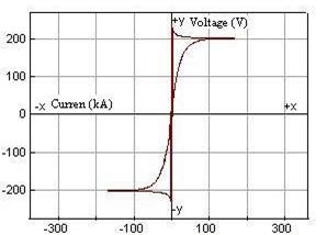
Figure 3. Voltage-current characteristic for the exponential-hyperbolic model
Analysis of Voltage Flicker: In this step, the sinusoidal form for voltage flicker is considered. For this purpose, based on equations (2) and (3), the following values are replaced:
|
|
(22) |

Also the simulation of the voltage flicker using the random voltage is carried out based on equations (2) and (4). The values used in the equation are:
|
Vatol = Vato2 = Vato3 = 200 V k1 = k2 = k3 = 1 |
(23) |
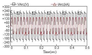
Figure 4. Waveforms of the arc voltage and current in the exponential-hyperbolic model
Results with TCR/FC Compensator
In this section, a TCR is added to the EAF. For the TCR, the inductance, L, of each branch is chosen to be equal to 25mH. Therefore, the three phase capacity of compensator is equal to 147.2Mvar. The value of reactive power of harmonic filters for the second, third and fourth harmonics are 44, 37 and 35Mvar, respectively.
With the given values and on the base of sinusoidal form of flicker voltage, the reactive power of furnace load, the system and TCR compensator are shown in Figure 5. Also, the waveforms of power factor changes at the PCC bus of the system, with and without TCR compensator considering sinusoidal voltage flicker, are shown in Figure 6. It is concluded from this figure that firstly, the changes in power factor is highly reduced. And secondly, by applying the TCR compensator, the average value of power factor is reduced from 0.60 to about 1, which is highly desirable.
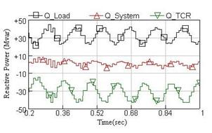
Figure 5. Waveform of reactive
power of furnace load (![]() ), System (
), System (![]() ), TCR (
), TCR (![]() ) considering sinusoidal
voltage flicker
) considering sinusoidal
voltage flicker
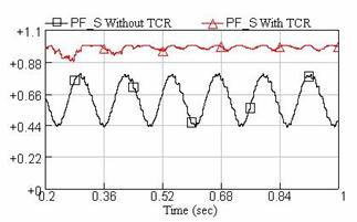
Figure 6. Waveform of power factor
of system at the PCC bus, with (![]() ) and without (
) and without (![]() ) TCR considering sinusoidal voltage flicker
) TCR considering sinusoidal voltage flicker
By considering Figures 5 and 6, it can be seen that the designed compensator is quite able to improve reactive power and power factor at the PCC bus of the system.
Also, the waveform of current of the TCR is determined and illustrated in Figure 7. In addition, Figure 8 shows the voltage of PCC bus after and before the use of the TCR. In this simulation, furnace load refers to total reactive power of load and filters. For this reason, the reactive power of the furnace load is negative.
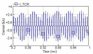
Figure 7. Waveform of current of TCR compensator considering sinusoidal voltage flicker
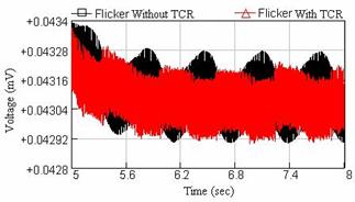
Figure 8. Waveforms of voltage
flicker at the PCC bus, with (![]() ) and without (
) and without (![]() ) TCR compensator considering sinusoidal voltage flicker
) TCR compensator considering sinusoidal voltage flicker
Regarding the recent figures, it is seen that in sinusoidal flicker case, the TCR current is also varied sinusoidally. Besides, reactive power of compensator will have sinusoidal deviation and therefore, the reactive power of the system has been held nearly constant. Meanwhile according to Figure 8, it is seen that flicker amounts of the PCC bus along with this compensator have been improved significantly.
By considering the random form of voltage flicker, the reactive power of furnace load, the system and TCR compensator are shown in Figure 9.
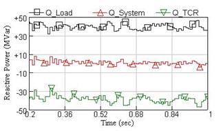
Figure 9. Waveform of reactive
power of furnace load (![]() ), System (
), System (![]() ) and TCR (
) and TCR (![]() ) considering random
voltage flicker
) considering random
voltage flicker
Also, the power factor changes graphs at the PCC bus of the system, with and without TCR compensating system considering random voltage flicker, are shown in Figure 10. It is concluded from this figure that by applying the TCR compensator, the average value of power factor is reduced from 0.45 to about 1.
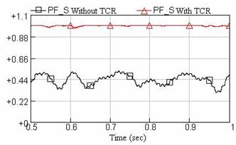
Figure 10. Waveform of power
factor of system at the PCC bus, with (![]() ) and without (
) and without (![]() ) TCR considering random
voltage flicker
) TCR considering random
voltage flicker
The waveform of current of the TCR is illustrated in Figure 11. Moreover, Figure 12 shows the voltage of PCC bus with and without using the TCR. In this simulation, furnace load refers to total reactive power of load and filters. For this reason, the reactive power of the furnace load is negative.
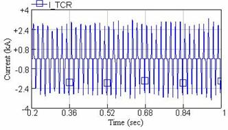
Figure 11. Waveform of current of TCR compensator considering random voltage flicker
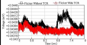
Figure 12. Waveforms of voltage
flicker at the PCC bus, with (![]() ) and without (
) and without (![]() ) TCR compensator considering random voltage flicker
) TCR compensator considering random voltage flicker
Considering the Figure 11, we will notice that by creating random flicker in the power system, the compensating current also like furnace load will have random deviations. This causes that flicker values certainly have decreased at source supplying an EAF. Therefore the reactive power of the system will desirably be compensated.
Discussion
Discussion of Harmonic analysis
In this section, regarding the importance of harmonic indices in power system as a parameter of power quality, the scale of THD due to TCR over power system and its own THD are simulated. Also the amount of the created harmonics in power system with and without TCR compensator will be evaluated completely. Noticing this point that the sinusoidal flicker can show THD profile more clearly, so in this section, all simulation results is based on the sinusoidal flicker. In this regard, Figure 13 shows the THD profile for current of TCR compensator. Also Figures 14 and 15 show THD profiles for current and voltage of the PCC bus, with and without TCR compensator considering sinusoidal voltage flicker, respectively. Moreover, the THD profile for current of the PCC bus is given in Figure 16.
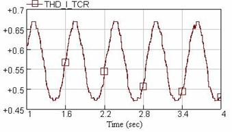
Figure 13. THD profile for current of TCR compensator (ITCR)
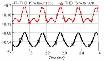
Figure 14. THD profile for current
of the PCC bus (IS), with (![]() ) and without (
) and without (![]() )
)
TCR compensator
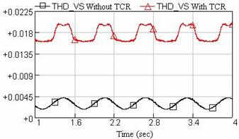
Figure 15. THD profile for voltage
of the PCC bus (VS), with (![]() ) and without (
) and without (![]() )
)
TCR compensator
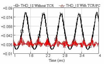
Figure 16. THD profile for current
of the PCC bus (IS), with (![]() ) and without (
) and without (![]() ) TCR/FC compensator
) TCR/FC compensator
Considering Figures 14 and 15, it can be seen that the compensator system of TCR is generating harmonics and causes injection of harmonics to voltage and current of power system. As mentioned before, in order to reduce harmonic components, the passive filters must be used, which the results is shown if Figure 16. Observing these curves show that by applying these filters, the amount of THD of current at the PCC bus has decreased from 8% to 3%. According to IEC 61000-2-1 and IEEE 519 standards, the THD values have been located in the authorized limits [20, 21].These advantages present the suitable design of the filters.
Table 1 shows the magnitude of existing harmonic in power system with and without TCR/FC compensator. Results of this table show that with applying the passive filters along with TCR compensator, the harmonic magnitude of current of the PCC bus has decreased remarkably. Also the amount of distortion values of the system has been decreased.
Table 1. Harmonic magnitude comparison in the system, with and without TCR/FC compensator (in volt)
|
With TCR/FC compensator |
Without TCR/FC compensator |
|
|||||
|
Current of furnace load |
Voltage of PCC bus |
Current of PCC bus |
Current of TCR compensator |
Current of furnace load |
Voltage of PCC bus |
Current of PCC bus |
Harmonic order |
|
0.004099 |
0.0002686 |
0.01645 |
0.00742 |
0.02088 |
0.0006708 |
0.02088 |
2HD |
|
0.002577 |
0.0001043 |
0.007269 |
0.4734 |
0.005011 |
0.00007 |
0.005011 |
3HD |
|
0.004553 |
0.0003988 |
0.005514 |
0.00627 |
0.008153 |
0.000381 |
0.008158 |
4HD |
|
0.02256 |
0.003831 |
0.04166 |
0.003183 |
0.05281 |
0.0004226 |
0.05281 |
5HD |
|
0.002625 |
0.0002363 |
0.00186 |
0.004062 |
0.004621 |
0.000211 |
0.004621 |
6HD |
|
0.006469 |
0.01593 |
0.1591 |
0.0741 |
0.02384 |
0.002953 |
0.02384 |
7HD |
Discussion of all Simulation Results
The following points are explained in order to give a general evaluation of simulation results:
1) Considering the results, it will be found out that the designed model has been successfully created the various conditions of power quality parameters in power system. Also by using voltage flicker in the load model of the EAF, the effective values of voltage and current of the furnace will change in proportion with the created flicker. So this model is obviously able to create various cases of the load in the case study system with proper accuracy.
2) With the connection of compensator to the source of supplying the EAF, it is observed that at first in sinusoidal flicker case, the TCR current will change in a sinusoidal form. Also the source of reactive power as mentioned initially has been held nearly constant (see Figure 5). However, if the TCR didn't apply, the source of reactive power can't follow the furnace reactive power, and cause deterioration in power quality of the system. Furthermore, the amounts of voltage flicker have reduced significantly according to Figure 8 of the simulation results.
Secondly, in random flicker case, the compensator has been able to follow the amount of random varieties and cause improvement of reactive power compensating while it has reduced voltage flicker too (see Figure 12).
3) The TCR compensating system causes harmonic injection to the system, and it generates harmonic. Of course, by inserting harmonic filters in parallel to TCR and selecting of delta configuration for the compensator, harmonic components can be reduced which are considerable in Table 1.
On the other hand, regarding the harmonic injection to the system by TCR compensator, the voltage and current waves of the system supplying the EAF is encountered with distortion. Of course with proper design of TCR compensator and its filters, the distortion amount has fallen to minimum values (see Figures 13 to 16).
Conclusion
In this paper, firstly a power system with the EAF was completely designed and simulated. Then various cases of furnace load including voltage flicker and unbalancing conditions over power system was evaluated and analyzed. Then a TCR compensator for this system with parallel capacitor was designed. In this process, the reactive power was measured so that maximum speed and accuracy are achieved. The results of the simulation show that when a TCR compensator is used with EAF, the total reactive power of system becomes perfectly fixed and the oscillations of the voltage of the PCC bus reduced considerably. Besides, designing of harmonic filters caused reduction of harmonic components and its distortions in power system and has also the role of generating reactive power. Finally, the use of this model along with the purposed compensator leads to saving energy consumption in the EAF.
References
1. Alonso M., Donsion M., An Improved Time Domain Arc Furnace Model for Harmonic Analysis, IEEE Transaction on Power Delivery, 2004, 19(1), p. 367-373.
2. Golkar M. A., Meschi S., MATLAB Modeling of Arc Furnace for Flicker Study, IEEE Conference on Industrial Technology (ICIT), 2008, p. 1-6.
3. Vervenne I., Van Reuse K., Belmans R., Electric Arc Furnace Modeling from a Power Quality Point of View, IEEE Conference on Electrical Power Quality and Utilisation (EPQU, p. 1-6), 2007.
4. Hernandez, A.; Mayordomo, J.G.; Asensi, R.; Beites, L.F. , A Method Based on Interharmonics for Flicker Propagation Applied to Arc Furnaces, IEEE Transactions on Power Delivery, 2005, 20(3), p. 2334-2342.
5. The Harmonics Working Groups, IEEE/ PES /T&D Committee, Modeling Devices with Nonlinear Voltage-Current Characteristic for Harmonic Studies, IEEE Transactions on Power Delivery, 2004, 19(4), p.1802-1811.
6. Beites L. F., Mayordomo J. G., Hernandes A., Asensi R., Harmonics, Inter harmonic, Unbalances of arc furnaces: a new frequency domain approach, IEEE Transactions on Power Delivery, 16(4), p. 661-668, 2001.
7. Mayordomo J. G., Beites L. F., Asensi R., Izzeddine M., Zabala L., Amantegui J., A New Frequency Domain Arc Furnace Model for Iterative Harmonic Analysis, IEEE Transactions on Power Delivery, 1997, 12(4), p. 1771-1778.
8. Fenghua W., Zhijian J., Application of Extended Kalman Filter to the Modeling of Electric Arc Furnace for Power Quality Issues, International Conference on Neural Networks and Brain (ICNN&B), 2005, pp. 991-996,.
9. Lok-Fu Pak Dinavahi V., Gary Chang Steurer M., Ribeiro P.F., Real-Time Digital Time-Varying Harmonic Modeling and Simulation Techniques, IEEE Transaction on Power Delivery, 2007, 22(2), p. 1218-1227,.
10. Mokhtari H., Hejri M., A New Three Phase Time-Domain Model for Electric Arc Furnaces Using MATLAB, Transmission and Distribution Conference and Exhibition 2002, Asia Pacific. IEEE/PES, 2002, pp. 2078- 2083.
11. Wangha L., Taewon K., Control of the Thyristor-controlled Reactor for Reactive Power Compensation and Load Balancing, IEEE Conference on Industrial Electronics and Applications (ICIEA), 2007, pp. 201-206.
12. Aguero J. L., Issouribehere F., Battaiotto P. E., STATCOM Modeling for Mitigation of Voltage Fluctuations Caused by Electric Arc Furnaces, IEEE Power Engineering Society General Meeting, 2006, p. 942-947.
13. Ramos B.N., Parga J.L. deC., An EMTP Study of Flicker Generation and Transmission in Power System Due to the Operation of an AC Electric Arc Furnace, 9th International Conference on Harmonics and Quality of Power, 2000, pp. 942-947,.
14. Parniani M., Mokhtari H., Hejri M., Effects of Dynamic Reactive Compensation in Arc Furnace Operation Characteristics and its Economic Benefits, Transmission and Distribution Conference and Exhibition, IEEE/PES, 2002, 2, p. 1044-1049.
15. Tavakkoli A., Ehsan M., Batahiee S., Marzband M., A SIMULINK Study of Electric Arc Furnace Power Quality Improvement by Using STATCOM, IEEE International Conference on Industrial Technology (ICIT, p. 1-6), 2008.
16. Benghanem M., Draou A., A New Modeling and Control Analysis of an Advanced Static VAR Compensator Using a Three-Level (NPC) Inverter Topology, Journal of Electrical Engineering, 2006, 57(5), p. 285-290.
17. Kouchi K., Hatano N., Yukihira K., Takeuchi Y., Ishiko T., Development of Control Scheme of a Line-Commutated SVC for Flicker Control, IEEE Conference on Power Engineering (IPEC), 2007, p. 579-584.
18. Miller T. J. E., Reactive Power Control in Electric Systems, Published by John Wiley & Sons, 1982.
19. Garcia-Cerrada A., Garcia-Gonzalez P., Collantes R., Gomez T., Anzola J., Comparison of Thyristor-Controlled Reactors and Voltage-Source Inverters for Compensation of Flicker Caused by Arc Furnaces, IEEE Transactions on Power Delivery, 2000, 15(4), p. 1225-1231.
20. IEC 61000-2-1, Electromagnetic Compatibility (EMC), Part 2: Environment, Section 1: Description of the Environment, 1990.
21. IEEE std 519, IEEE Recommended Practices and Requirements for Harmonic Control in Electric Power Systems (ANSI), 1992.