The Power Quality Compensation Strategy for Power Distribution System Based on Hybrid Parallel Active Power Filters
Rachid DEHINI1*, Benachaiba CHELLALI1, Brahim BERBAOUI1, Brahim FERDI 1, Boumediène ALLAOUA1
1 Faculty of the sciences and technology, Department of Technology, Bechar University B.P 417 BECHAR (08000), Algeria.
E-mail: dehinirachid@ yahoo.fr
(*Corresponding author: Phone: +213-558 548 639)
Abstract
In this paper, the main aim is to confront the performance of shunt active power filter (SAPF) and the shunt hybrid active power filter (SHAPF) to achieve flexibility and reliability of the filter devices. Both of the two devices used the classical proportional-integral controller for pulse generation to trigger the inventers MOSFET’s. In the adopted hybrid active filter there is a passive power filter with high power rating to filter the low order harmonies and one active filter with low power rating to filter the other high order harmonies. In order to investigate the effectiveness of (SHAPF), the studies have been accomplished using simulation with the MATLAB-SIMULINK. The results show That (SHAPF) is more effective than (SAPF), and has lower cost.
Keywords
Shunt active power filter; Passive power filter; Nonlinear loads, Hybrid active filter.
Introduction
Due to proliferation of power electronic equipment and nonlinear loads in power distribution systems, the problem of harmonic contamination and treatment take on great significance .These harmonics interfere with sensitive electronic equipment and cause undesired power losses in electrical equipment [1-3]. In order to solve and to regulate the permanent power quality problem introduce by this Current harmonics generated by nonlinear loads such as switching power factor correction converter, converter for variable speed AC motor drives and HVDC systems, the resonance passive filters (RPF) have been used; which are simple and low cost. However, the use of passive filter has many disadvantages, such as large size, tuning and risk of resonance problems which decrease more the flexibility and reliability of the filter devices
Owing to the rapid improvement in power semiconductor device technology that makes high-speed, high-power switching devices such as power MOSFETs, MCTs, IGBTs , IGCTS, IEGTs etc. usable for the harmonic compensation modern power electronic technology, Active power filter (APF) have been considered as an effective solution for this issue, it has been widely used.
One of the most popular active filters is the Shunt Active Power Filter (SAPF) [6-11]. SAPF have been researched and developed, that they have gradually been recognized as a workable solution to the problems created by non-linear loads, unfortunately, because of the high cost operation, the (SAPF) is not a cost-effective solution.
The disadvantages of (RPF) and (SAPF) orientate the researchers toward shunt hybrid active power filter (SHAPF), consequently (SHAPF) has become more attractive [1]. The (SHAPF) involve a (RPF) connected in parallel with (SAPF), this solution allows the use of (SAPF) in the large power system avoiding the expensive initial cost and improves the compensation performance of passive filter remarkably.
In this paper, a (SHAPF) is presented both to achieve harmonic currents mitigation and to compensate reactive power in an industrial power distribution .This filter device is analyzed by estimating the effect of (RPF) join and disjoin on its compensation performance. In the adopted hybrid active filter there is a passive power filter with high power rating to filter the low order harmonies the 5th, 7th harmonic current and one active filter with low power rating to filter the other high order harmonies.
The functioning of (SAPF) is to sense the load currents and extracts the harmonic component of the load current to produce a reference current ic* a block diagram of the system is illustrated in Fig. 1. The reference current consists of the harmonic components of the load current which the active filter must supply. This reference current is fed through a controller and then the switching signal is generated to switch the power switching devices of the active filter such that the active filter will indeed produce the harmonics required by the load. Finally, the AC supply will only need to provide the fundamental component for the load, resulting in a low harmonic sinusoidal supply.
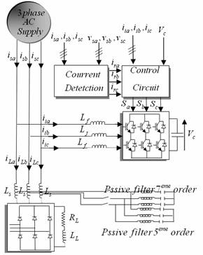
Figure 1. Schematic diagram of shunt (SHAPF)
Reference Source Current Generation
In order to determine harmonic and reactive component of load current, reference source current generation is needed. Thus, reference filter current can be obtained when it is subtracted from total load current. For better filter performance, generation of reference source current should be done properly. For this purpose several methods such as pq-theory, dq-transformation, multiplication with sine function and Fourier transform have been introduced in literature [31]. In this paper the instantaneous reactive power theory method is used for extraction of reference.
This concept basically consists of a variable
transformation from the a, b, c reference frame of the instantaneous
power, voltage and current signals to the ![]() reference frame. The
instantaneous values of voltages and currents in the
reference frame. The
instantaneous values of voltages and currents in the ![]() coordinates can be
obtained from the following equations:
coordinates can be
obtained from the following equations:
|
|
(1) |


where A is the transformation matrix and is equal to:
|
|
(2) |

This transformation is valid if and only if ![]() and also if the voltages are balanced and
sinusoidal. The instantaneous active and reactive powers in the
and also if the voltages are balanced and
sinusoidal. The instantaneous active and reactive powers in the ![]() coordinates
are calculated with the following expressions:
coordinates
are calculated with the following expressions:
|
|
(3) |
|
|
(4) |
The values of p and q can be expressed From Eqs. (3) and (4) in terms of the dc components plus the ac components, that is:
|
|
(5) |
|
|
(6) |
where:
![]() : is the dc
component of the instantaneous power p, and is related to the conventional
fundamental active current.
: is the dc
component of the instantaneous power p, and is related to the conventional
fundamental active current.
![]() : is the ac
component of the instantaneous power p, it does not have average value, and is
related to the harmonic currents caused by the ac component of the
instantaneous real power.
: is the ac
component of the instantaneous power p, it does not have average value, and is
related to the harmonic currents caused by the ac component of the
instantaneous real power.
![]() : is the dc
component of the imaginary instantaneous power q, and is related to the
reactive power generated by the fundamental components of voltages and
currents.
: is the dc
component of the imaginary instantaneous power q, and is related to the
reactive power generated by the fundamental components of voltages and
currents.
![]() : is the ac
component of the instantaneous imaginary power q, and is related to the
harmonic currents caused by the ac component of instantaneous reactive power.
: is the ac
component of the instantaneous imaginary power q, and is related to the
harmonic currents caused by the ac component of instantaneous reactive power.
In order to compensate reactive power and current
harmonics generated by nonlinear loads, the reference signal of the shunt
active power filter must include the values of ![]() and
and ![]() . In this case
the reference currents required by the SAPF are calculated with the following
expression:
. In this case
the reference currents required by the SAPF are calculated with the following
expression:
|
|
(7) |

The final compensating currents components in a, b, c reference frame are the following:
|
|
(8) |

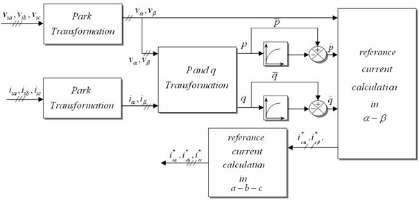
Figure 2. Block diagram for the instantaneous active and reactive power
DC Voltage Control
The (SAPF) control strategy, involves not only the
production of currents whether to eliminate the undesired harmonics or to
compensate reactive power. But also to recharge the capacitor value requested
VDC voltage in order to ensure suitable transit of powers to supply the
inverter. The storage capacity C absorbs the power fluctuations caused by the
compensation of the reactive power, the presence of harmonics, the active power
control and also by the losses of the converter. The average voltage across the
capacitor terminals must be kept at a constant value. The regulation of this
voltage is made by absorbing or providing active power on the electrical
network. The correction of this voltage must be done by adding the fundamental
active current in the reference current of (SPAF)[30]. To realize these
objectives, a proportional integral (PI) voltage feedback control as shown in
Fig. 3, is added to regulate the capacitor dc voltage of the (SAPF). In this
circuit, the actual dc capacitor voltage is detected and compared with the
reference value, and the error is amplified then is added to the ![]() , the output of high-pass filter in Fig. 2.
Therefore, active power lowing into the capacitor will be changed and the dc
voltage cab be controlled.
, the output of high-pass filter in Fig. 2.
Therefore, active power lowing into the capacitor will be changed and the dc
voltage cab be controlled.
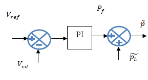
Figure 3. Control of DC Voltage using conventional PI controller (CPI)
Results
The performance of the (SHAPF) was examined through simulations. The system model was implanted in Matlab / Simulink environment. The (SAPF) was designed to compensate harmonics caused by nonlinear loads when the network is small relative to the load (Ssc / SL = 100). The system model parameters are shown in Table I.
Table 1. System parameters
|
Active Filter Parameters |
|
|
Supply phase voltage U |
220 V |
|
Supply frequency fs |
50 Hz |
|
Filter inductor Lf |
0.7 mH |
|
Dc link capacitor Cf |
0.768474 mF |
|
Smoothing inductor Lsmooth |
70 μH |
A three-phase diode rectifier with an RL load was used as a harmonic producing load. The load (resistance was 10/3 Ω and the inductance 60 mH.)
In second place, two resonant passive filters tuned up to the frequency 250Hz (h5) and 350Hz (h7) are simultaneously connected in parallel with (FAP) in load side at 0.4s. Both resonant passive filters have the following characteristics:
Table 2. Passive filters characteristics Description
|
Resonant passive filter (h5) |
resonant passive filter (H7) |
|
Resonance frequency 250Hz (h5) |
Resonance Frequency 350Hz (H7) |
|
|
|
|
|
|
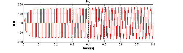
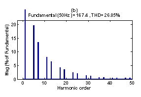
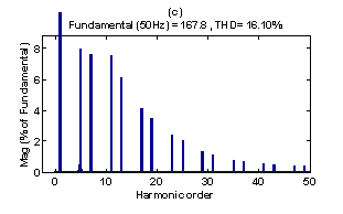
Figure 4. (a.1) Simulated phase-a the load current waveforms Isa(A).(b.1) Harmonic spectrum of load current Phase ‘a’, with (SAPF).(c.1) Harmonic spectrum of load current Phase ‘a’, with (SHAPF)
|
|
|
|
|
|
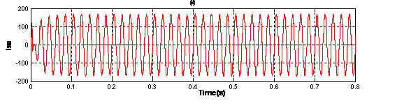
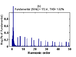
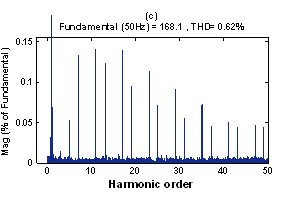
Figure 5. (a.2) Simulated phase-a the supply current waveforms Isa.(b.2) Harmonic spectrum of supply current Phase ‘a’, with (SAPF).(c.2) Harmonic spectrum of supply current Phase ‘a’, with (SHAPF)
|
|
|
|
|
|
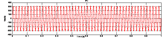
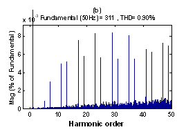
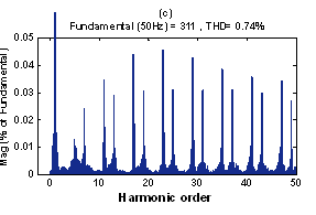
Figure 6. (a.3) Simulated phase-a the supply voltage waveforms Vsa(A).(b.3) Harmonic spectrum of supply voltage Phase ‘a’, with (SAPF).(c.3) Harmonic spectrum of supply voltage Phase ‘a’, with (SHAPF)
|
|
|
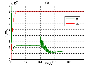
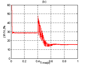
Figure 7. (a) (SAPF) apparent power (Sf) and (Load) apparent power (SL).(b) The percentage of (SAPF) apparent power compared to (Load) apparent power
|
|
|
|
(Peak) Iinj = 88.56,( 35.5 rms) |
(Peak) Iinj =58.01,(19.33 rms) |
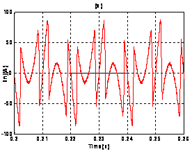
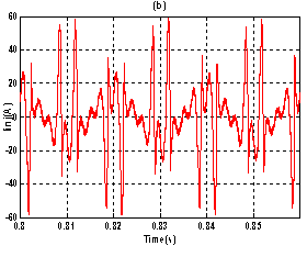
Figure 8. (a.4) Simulated phase-a the injected current waveforms Iinja (A) with (SAPF).(b.5) Simulated phase-a the injected current waveforms Iinja (A) with (SHAPF)
|
(b) |
||
|
|
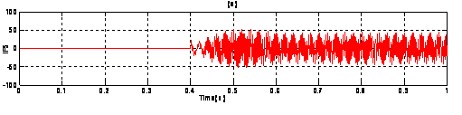
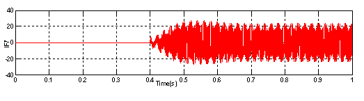
Figure 9. (a) Simulated phase-a the passive filter current waveforms iF5 with (SHAPF).(b) Simulated phase-a the passive filter current waveforms iF7 with (SHAPF)
|
|
|
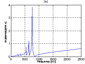
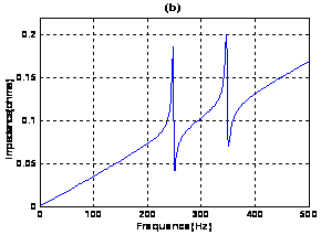
Figure 10. (a)network impedance with (5h, 7h, 11h, 13h, and 17h high-pass).(b)network impedance with (SAPF)and resonant passive filter (5h ,7h)
Discussions
The RPF (h5 + h7) has further improved the functioning of the (SAPF) and declined further its power.
§ According to figures 6. (b) and 6.(c), there is a remarkable improvement THDV (from 0.90% to 0.74%).
§ According to figures 5. (b) and 5. (c), there is a remarkable improvement THDI (from 1.02% to 0.62%).
§ The 5th and 7th harmonics are not completely eliminated but they are strongly attenuated (Fig. 5. (b) and 5. (c)).
§ According to figures 7. (a) and 7. (b), the percentage of (SAPF) apparent power (SF) compared to (Load) apparent power (SL) has declined from 28.93% to 15.75%) and has become very reasonable.
According to simulation results obtained in this work, we can say that the (RPF) can be an effective solution for the compensation of harmonic currents for low and means power network (relative to the load) with a risk of parallel resonance, figures 10. (a) and 10. (b). The (SAPF) presents the ideal solution for currents harmonics compensation regardless of the power network, but this solution is costly. The (SHAPF) justified its use by reducing the apparent power of the used (SAPF) and improving its operation especially if the network is low or medium power.
Conclusions
The paper presents the development of flexibility and reliability of the filter device by coming together the advantages of resonance passive filters (RPF) and Shunt Active Power Filter (SAPF) for leaving behind their drawbacks. A (SHAPF) is adopted in order to achieve the harmonics and reactive power compensation. The well adjusted (SHAPF) consists of passive filter with larger rated power is used to filter the low order harmonics and one active filter with low power rating to filter the other high order harmonies. Measured up to (SAPF), the (SHAPF) can decrease the power rating of active part. Both the compensation performance and the parallel resonance damping can be improved by the later compared with resonance passive filters (RPF) used only and (SAPF). From the comparative analysis, hybrid filter is effective and economic for solving harmonics problems in large capacity nonlinear load.
References
1. Xi Z., Fang Z., Rui D., Wanjun L., Pengbo Z., Zhaoan W., Development of a Parallel Hybrid Power Filter with Respective Harmonic Compensation Method, IEEE, 2006, p. 1733-737.
2. Rahmani S., Hamadi A., Mendalek N., Al-Haddad K., A New Control Technique for Three-Phase Shunt Hybrid Power Filter, IEEE, 2009.
3. Wu J., He N., Xu D., A 10KV Shunt Hybrid Active Filter for a Power Distribution System, IEEE, 2008, p. 927-932.
4. Xiaohua T., Yue W., Xiao Z., Weibin S., Ying T., Zhaoan W., An Overall Optimization Strategy for Novel Hybrid Parallel Active Power Filters Based on Genetic Algorithm, IEEE, 2006, p. 145-150.
5. Abdelmadjid C., Jean-Paul G., Fateh K., Laurent R., On the Design of Shunt Active Filter for Improving Power Quality, IEEE, 2008.
6. Tavakoli B.M., Pashajavid E., An efficient procedure to design passive LCL-filters for active power filters, Elsevier, 2008, p. 606-614.
7. Adel M.A., David A.T., A Three-phase Hybrid Series PassiveBhunt Active Filter System, IEEE, 1999, p. 875-881.
8. He N., Wu J., Xu D., A Novel Shunt Hybrid Power Filter for Suppressing Harmonics, IEEE ISIE 2006, July 9-12, 2006, Montreal, Quebec, Canada, pp. 1155-1160, 2006.
9. Salem R., Kamal A., Hadi Y. K., A comparative study of shunt hybrid and shunt active power filters for single-phase applications: Simulation and experimental validation, Published by Elsevier, 2006, pp. 345-359.
10. Huann K.C., Bor R.L., Kai Y., Kuan W.W., Hybrid Active Power Filter for power quality compensation, IEEE, 2005, p. 949-954.
11. Yi N.G., Juan Z., Jian C., Xing D.J., Optimal Design of Passive Power Filters Based on Knowledge-based Chaotic Evolutionary Algorithm, IEEE, 2008, p. 535-539.
12. Taruna J., Shailendra J., Ganga A., Comparison of Topologies of Hybrid Active Power Filter, IET-UK International Conference on Information and Communication Technology in Electrical Sciences (ICTES 2007), Dec. 20-22, pp. 503-509, 2007.
13. Hurng L.J., Jinn C.W., Yao J.C., Ya T.F., A Novel Shunt Hybrid Power Filter for Suppressing Harmonics, IEEE Transactions On Power Delivery, 2005, 20(2), p. 1507-1513.
14. Ruixiang F., Min S., An L., Zhikang S., Configuration of A Novel Hybrid Active Power Filter and its control method, IEEE, 2009.