ANN Speed Sensorless Fuzzy Control of DRFOC Induction Motor Drives
Mouna BEN HAMED 1*, Lassaâd SBITA1 and Walid ABBOUD2
1 Research Unit of Modeling, Analysis and Control of Systems - MACS, National Engineering School of Gabès - ENIG, Zrig 6029 Gabès, Tunisia
2 Research Unit of Modeling, Analysis and Control of Systems - MACS, Ciment Society of Gabes (CSG), Tunisia.
E-mail: benhamed2209@yahoo.fr, lassaad.sbita@enig.rnu.tn, walid.abboud@yahoo.fr, benhamed2209@yahoo.fr
(*Corresponding author: Phone: 95851313)
Abstract
The aim of this paper is to present a full digital implementation of a sensorless speed direct orientation field controlled induction motor drive. Thanks to their advantages, the fuzzy logic is used to control the Squirrel Cage Induction Motor rotor speed and a neural network is used to reconstruct it.
Experimental results for a 1kw induction motor are presented and analyzed using a dSpace system with DS1104 controller board based on digital signal processors (DSP). Obtained results demonstrated that the proposed sensorless control scheme is able to obtain high performances.
Keywords
ANN; Estimation; Fuzzy logic; Speed; Control; DRFOC; Induction motor
Introduction
Thanks to the theory of the vector control, high performance speed and torque responses are achieved for a squirrel cage induction motors (SCIM) nowadays [1]. Driven by a vector control, a SCIM behaves similar to a separately excited DC machine in which the torque and flux are controlled separately [2]. The most important drawbacks in using this theory is the need to mount the speed sensor in closed loop configuration which results to several economical and technical problems [3]. Controlled SCIM drives without mechanical sensor for speed control have the attraction of low cost and high reliability [3] and [4]. The estimation of rotor speed is based excessively on measured terminal voltages and currents [8], [5], [6] and [7]. So the performance of the controller is depended to the robustness of the speed estimation. In recent years, speed estimation based on the artificial intelligence techniques such as fuzzy logic and neural network have been widely used [7], [8], [9] and [10]. Since these approaches doesn’t require the knowledge of a mathematical machine model, the algorithm remains robust despite of parameter deviation and noise measurement [11] and [12].
In this paper, a fuzzy logic controller is built in the speed loop control. The feedback signal comes from the neural network observer. It is trained off line using the back propagation algorithm. The data for training are picked up when the motor is working in closed loop at various values of speeds and loads. The proposed sensorless control scheme is implemented for a real time experimental validation.
Figure 1. The bloc diagram of the proposed induction motor drive system
Induction Motor Model
Assuming linear magnetic circuits, equal mutual inductances and neglecting iron losses, the induction motor mathematical model in the stationary frame is formulated as [13]:
 (1)
(1)
The stator and rotor winding flux linkages are expressed as:
 (2)
(2)
where iαs,
iβs, vαs, vβs, are respectively
the stator currents and voltages components, Φαs, Φβs,
Φαr, and Φβr, are respectively the
stator and rotor fluxes components; rs and rr are
respectively the stator and the rotor resistances, Ls, Lr and
M are respectively the stator self, the rotor self and the mutual inductances; ![]() is the
leakage coefficient and
is the
leakage coefficient and ![]() is the rotor speed.
is the rotor speed.
The electromagnetic torque developed by the motor is expressed in terms of rotor flux and stator currents as:
![]() (3)
(3)
While the load torque acts as a disturbance via the mechanical relation:
![]() (4)
(4)
Where J is the moment of inertia of the rotor and TL is the load torque.
Proposed Scheme of the Drive System
The bloc diagram of the proposed induction motor drive system is shown in Figure. 1. The closed loop control scheme consists of an inner currents control loops and an outer speed and flux control loops. The feedback signals for the outer control loops are estimated using an on line data of motor terminals in terms of stator voltages and currents. The stator’s voltages and currents are sensed using Hall Effect voltage and current sensors. The signals corresponding to voltage and current of the stator are fed to the processor through the dSpace system with DS1104 controller board. Thereafter, the rotor speed and the rotor flux are estimated inside the processor using the sensed values of stator terminals (Figure 2). The estimated speed ωANN(k) using the artificial neural network is used with the reference ωref(k) to compute the speed error, which is processed in a fuzzy logic controller. The output of the speed controller which represents the target electromagnetic torque is used to compute the target reverse stator current iqsref. The later is applied to a current limiter which sets a limit on this reference current. This limit on the target reverse current is desirable to operate the devices of the inverter circuit in their safe range of current. The current signals iqs and iqsref are processed in a PI controller to generate the reverse stator voltage vqs.
The estimated rotor flux is used with the reference flux Φdrref to compute the flux error, which is processed in a PI controller. The output of the flux controller which represents the target direct stator current idsref is applied to a current limiter which sets a limit on this reference current. The two current signals ids and idsref are processed in a PI controller to generate the direct stator voltage vds.
The estimated slip speed using the target rotor flux and
the target reverse stator current is added to estimated rotor speed to get the
synchronous one ωs. The obtained vds, vqs,
and ωs are fed to the d - q ![]() a – b - c bloc to get the
reference target stator voltages vasref, vbsref, and vcsref.
The target stator voltages are processed in the PWM bloc to provide an
appropriate switching pattern to the devices of the fed inverter.
a – b - c bloc to get the
reference target stator voltages vasref, vbsref, and vcsref.
The target stator voltages are processed in the PWM bloc to provide an
appropriate switching pattern to the devices of the fed inverter.
Direct Rotor Field Oriented Control Scheme
For the direct rotor field oriented control (DRFOC), the rotor flux vector is aligned with d axis and setting the rotor flux to be constant equal to the rated one which means Φdr = Φr and Φqr = 0. With respect to this condition, the estimated rotor flux and the slip speed are given as:
![]() (5)
(5)
![]() (6)
(6)
With τr = Lr/rr is the rotor time constant.
Figure. 2 show the proposed DRFOC scheme of the SCIM.
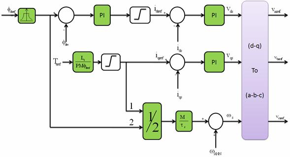
Figure 2. DRFOC scheme of induction motor
Neuronal Network: Basic Principles
A neural network is a powerful data modelling tool that is able to capture and represent complex input/output relationships. It's an information processing system that is non-algorithmic, non-digital, and intensely parallel. It consists of a number of very simple and highly interconnected processors called neurons, or like their biological pattern, neural cells in the brain, neurons. The neurons are Connected by a large number of weighted links, over which signal can pass [14]. Real neurons have a finite dynamic range from nil response to the full firing rate, which is modeled by a non-linear, levelling off at 0 and 1. The additional bias term that determines the spontaneous activity of the neuron in the absence of inputs is modeled by a threshold value [15]. The transfer function of a neuron would consist of two steps. First, the neuron computes the weighted input receiving along its input connection. The second step consists of converting the net input to an activation level. Artificial neural network technique is based on a learning process. It is defined as changing the synaptic weights of each interconnection in the network to update it until the target error is reached. Generally, the back propagation method is used for adjusting the neural network weights during the training phase. The basic back-propagation algorithm consists of three steps. The input pattern is presented to the input layer of the network. These inputs are propagated through the network until they reach the output units. This forward pass produces the actual or predicted output pattern. As back-propagation is a supervised learning algorithm the desired outputs are given as part of the training vector. The actual network outputs are subtracted from the desired outputs and an error signal is produced. This error signal is then the basis for the back-propagation step, whereby the errors are passed back through the neural network by computing the contribution of each hidden processing unit and deriving the corresponding adjustment needed to produce the correct output. The connection weights are then adjusted and the neural network has just learned from an experience. The use of a neural network in control or modeling consists of an association of some inputs with some outputs. In this case, for each set of inputs, there is a set of outputs. To accomplish this operation, the net will have to be trained in a first phase. It is not necessary to carry out this phase in real time and give the net all possible inputs - outputs combinations since it has the capacity to generalize results starting from a limited set of inputs outputs. The most significant points, to keep in mind when defining the structure and operation of neural nets, are mainly the choice of the inputs and outputs. Some inputs should be chosen that determine completely the target output and must be easily measured so that the used hardware will be simplified.
To train the neural network, the calculation of the synaptic weights should be done.
The training algorithm of the neural network is as follows [16], [17] and [18]:
1st step: initially randomize the weights from -0.5 to 0.5,
2nd step: obtain the input data of the neural network,
3rd step: calculate the error between real and observed outputs,
4th step: adjust the weights of the neural network,
5th step: calculate the output of the neural network,
6th step: repeat 2nd step until the stipulated error is reached.
Neuronal Network Speed Observer
By replacing stator flux with its expression and eliminating the rotor current in (1), we obtain:
 (7)
(7)
Based on these equations, we recognize the well known models: the voltage model (VM) and the current model (CM). The equality between the rotor fluxes deduced from the models, we obtain [19]:
 (8)
(8)
Multiplying
the first equation by ![]() and the second one by
and the second one by![]() , we establish:
, we establish:
 (9)
(9)
In the vector control, ![]() and
and ![]() are
constants. Therefore,
are
constants. Therefore, ![]() varies with respect to
varies with respect to![]() ,
,![]() ,
, ![]() and
and ![]() . Hence, the
significant inputs which determine completely the rotor speed are
. Hence, the
significant inputs which determine completely the rotor speed are![]() ,
,![]() ,
, ![]() and
and ![]() .
.
It is better to obtain a neural network speeds observer which observes the whole range of speeds (from negative to positive values). By looking at extent training data, we find them very huge and the neural network observer finds many training problems because of the amount of information to be learnt by the neural network. Many solutions are proposed [20] and [21]. For example, we can increase the number of layers and neurons. However, this creates a problem of computation time and memory capacity. A simple and easy solution is to learn only the range of the positive speed. It is known that the relation between positive and negative speeds is a minus mark in the command issue. How to detect the negative speeds? If the reference speed becomes negative, the speed becomes also negative and vis versa. To make the neural network available in negative speeds, an absolute value is added to the bipolar inputs of the neural network and a sign function is implemented. Using this technique, we save time, memory capacity and we observe the speed in the whole range (from positive to negative). The final structure of the neural network used is a multilayer net with the three layers. The first one contains four neuron inputs vαs, vβs, iαs, and iβs, the second one has two hidden layers and the third one by one neuron to give observed speed. This final structure is chosen by trial and error method. The sigmoid function has an output signal varying between 0 and 1. Therefore, we adopt the signals by dividing the output by its nominal value. The way of training the neural network consists of sampling the training data corresponding to the positive speed and presenting these data base to the back propagation algorithm [22]. The training algorithm of the neural network speed observer is as follows:
1st step: initially randomize the weights from -0.5 to 0.5,
2nd step: obtain the stator currents and voltages,
3rd step: calculate the error between real and observed speeds,
4th step: adjust the weights of the neural network,
5th step: calculate the output of the neural network,
6th step: repeat 2nd step until the stipulated error is reached.
The internal structure of the neural network speed observer is shown in Figure. 3.
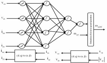
Figure 3. The internal structure of the neuronal network speed observer
Fuzzy Logic Speed Controller
According to George Boole, who published the article “Investigations of the Laws of Thoughts” in 1854, human beings think and take decisions on the basis of logical “yes/no” or “true/false” reasoning? This gave birth to Boolean algebra and gradually became the basis of our modern digital computers [23]. Lotfi Zadeh argued that human thinking is often fuzzy or uncertain in nature, and does not always follow crisp “yes/no” logic [24]. He originated the “fuzzy logic” theory in 1965 and created a storm of controversy in the intellectual community. Fuzzy logic is basically multi-valued logic where the variable is represented by linguistic fuzzy sets and each fuzzy set is represented by a membership functions (MFs) [25] and [26].
Although triangular type MF is very common, trapezoidal, Gaussian, sigmoidal and polynomial types are also used.
Fuzzy logic is often applied in the robust control of a feedback system with parameter variation problem and load torque disturbance. The control is defined by a set of IF … THEN…production rules.
The controller observes the pattern of the feedback loop error (E) and its change rate (dE/dt), i.e. change in error in a finite interval (CE) and generates the incremental control signal (∆U) through the fuzzy inference system that consists of three basic elements: fuzzyfication of input variables, evaluation of control rules by using Membership functions (MFs) and rule base, and defuzzification. The fuzzy variables (E, CE and DU) in the “universe of discourse” are usually handled in per unit (pu) form by using the respective scale factors shown for versatility. The output signal DU is then integrated to generate the actual control signal.
The structure of a standard fuzzy controller is presented in Figure 4.
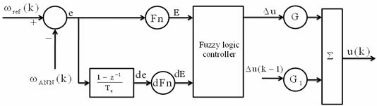
Figure 4. Structure of fuzzy controller
In the fuzzy control implementation, the input crisp values of the variables are processed through fuzzification, application of fuzzy operator (AND, OR, NOT) in the IF part of the rule, implication to the THEN part of the rule, aggregation of the rule outputs and then finally defuzzification to convert the fuzzy output to a crisp value [26]. The defuzzification basically consists of finding the center of the output area (COA method) given by the general formula (9):
 (10)
(10)
Consider the fuzzy speed control system of an induction motor drive with indirect vector control where E and CE are the signals from the speed loop and ∆U is the crisp output signal. The ∆U signal after integration constitutes the target electromagnetic torque command Teref for the DRFOC drive. Figure 5 shows the fuzzy sets with triangular MF set of each signal and input output control surface. The universe of discourse of each variable is expressed in pu values. All the MFs are symmetrical in nature. There are five MFs for each input and output variables. Table 1 shows the rule matrix which contains 5×5 = 25rules,
The design of fuzzy controller is essentially the knowledge base design that consists of formulation of MFs and the rule matrix [20]. This design is often based on trial-and-error approach based on performance experience about the plant. The use of software tools (such as MATLAB Fuzzy Logic Toolbox) and computer simulation study helps fast and optimum design of the system.
The torque command is then computed (10).
Te(k) = Te(k-1) + G∆Te (11)
with G is a tuned gain.
For this control law, only at steady state, the speed error goes to zero, however, at dynamic state, the tracking error is significant.
To minimize the error at dynamic state, a new control law is proposed. It is defined as:
Te(k) = Te(k-1) + G∆Te(k) + G1∆Te(k-1) (12)
Here G1 is also tuned gain.
Table 1. Rule matrix for fuzzy logic speed controller
|
∆u(k) |
CE |
|||||
|
GN |
PN |
Z |
PP |
GP |
||
|
E |
GN |
GN |
GN |
PN |
PN |
Z |
|
PN |
GN |
PN |
PN |
Z |
PP |
|
|
Z |
PN |
PN |
Z |
PP |
PP |
|
|
PP |
PN |
Z |
PP |
PP |
GP |
|
|
GP |
Z |
PP |
PP |
GP |
GP |
|
(a)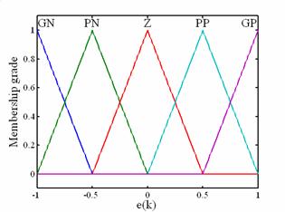 (b)
(b)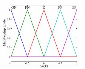
(c)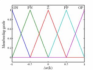 (d)
(d)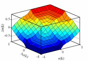
Figure 5. The memberships of the: a – Error, b - Error variation, c - Command variation, d - Control surface
Implementation of the Drive System
We have tested the neural network for fuzzy controlled speed sensorless direct field oriented control of induction motor drive at different speed values under no load and with load applied.
It consists of an appropriate hardware and its software components.
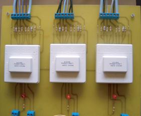
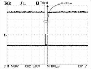
(a) (b)
Figure 6. (a) Switching signals drivers’ circuit of the inverter - (b) switching signals of IGBT’s half bridge with dead time of 3.25s
Figure 7 shows the experimental set up drive system of the used configuration.
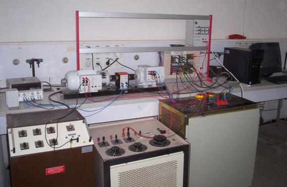
Figure 7. A photo of the experimental set up
The major parts of the drive system are:
|
(a) Neural network speed observer |
(b) Fuzzy logic speed controller |
|
(c) Current controllers |
(d) Rotor flux estimator |
|
(e) Rotor flux controller |
(f) IGBT’s Gate drivers |
|
(g) Voltage source inverter (vsi) based on IGBT transistors |
(h) Direct current voltage bus |
|
(i) Space controller board DS1104 and its connector panel |
(j) Voltage, current and speed sensors |
Some of them are implemented through software and they are mainly speed observer, speed controller, current controllers, rotor flux estimator and rotor flux controller. The experimentation has been achieved with the help of Matlab/Simulink package and dSpace system with DS1104 controller board based on digital processors (DSP). The voltage source inverter utilizes a diode rectifier half bridge with dc bus voltage feeding the three IGBTs. The power circuit part is composed of intelligent power modules with rated 75A, 1200V to drive the induction motor. Intelligent power modules are conducted with insulated gate bipolar transistors working at a frequency up to 20KHZ with a dead fixed time of 3.25µs as it is shown in Figure 6(b). The pulse width modulation (PWM) signals to control the power modules are generated by dSpace system. An optical isolation and an amplification of the switching signals are provided through on optocoupler PC900V. After that the obtained signals are updated using three drivers SKHI22A (Figure 6(a)). The sampling period of 1ms is selected since the computation time of the algorithm is about 0.1ms. We measure two stator current using Hall type sensors LM LA 100 – P through 16bits analogical – digital converter. An incremental sensor encoder delivering 1024 pulses per revolution is mounted on the rotor shaft only for comparison of the observed and real speed of the induction motor. A 1kw Direct Current Generator (DCG) supplying a variable resistor bank is used as variable load for 1kw induction motor. The control and observation algorithms are implemented in a Matlab/Simulink package, compiled to machine language and downloaded on a Real Time Interface dSpace DS1104 (Figure 8).
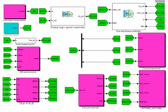
Figure 8. SCIM speed sensorless digital implementation using dSpace 1104 RTI – Simulink
Experimental Results
Many experiments were carried out under various operating conditions to verify the performances of the proposed neural network peed sensorless for a fuzzy controlled s direct field oriented SCMI drives both with and without load torque appliance. Figures 9 to 22 illustrate the experimental results. The obtained results at variable target speed under no load are presented in Figures 9 to 14. From Figure 9, it is shown that the fuzzy logic controlled speed is following the measured one. The maximum observation error is 35rpm (3.5%) as it is shown in Figure 10. In the same way, with the proposed neural network observer, the measured and observed speeds follow the target one. In Figure 13 is presented the direct stator currents. The real direct stator current follows the target one indicating that the decoupling of the induction motor is well established.
In Figures 15 to 22, a DC generator supplying a variable resistive bank has been connected to the motor as a load. In this case, as it can be seen from the Figures 18 and 22, the machine needs more current. The reverse stator current increase as it is directly proportional to the electromagnetic torque. The direct-stator current remains constant indicating the decoupling is guaranteed. The neural network observed speed and the measured one follow the target indicating the high performance of the proposed fuzzy logic controller. As it is seen from the experimental results the proposed neural network for fuzzy logic controlled speed sensorless direct field oriented induction motor drives has good performances.
Results without Load
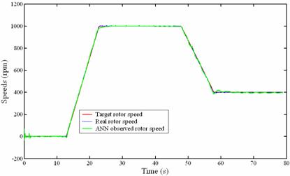
Figure 9. Measured, ANN's observed speeds at variable target speeds under load torque appliance in experimentation
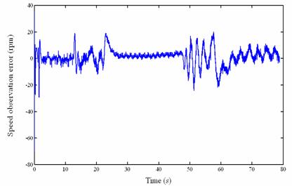
Figure 10. Speed observation error at variable target speeds under no load in experimentation
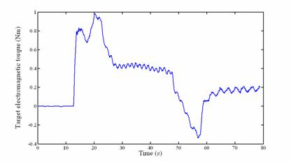
Figure 11. Target electromagnetic torque at variable target speeds under no load in experimentation

Figure 12. Reverse stator current at variable target speeds under no load in experimentation
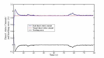
Figure 13. Real and target direct stator currents and tracking error at variable target speeds under no load in experimentation
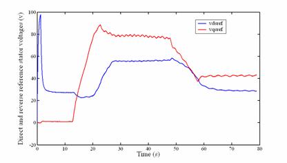
Figure 14. Direct and reverse stator voltage at variable target speeds under no load in experimentation
In Figure 15, the machine has been initially set to operate at 1000 rpm in steady state. A sudden resistive load has been then applied from 28 to 36 s to the motor shaft. The maximum speed error is 28 rpm (2.8%) (Figure 16).
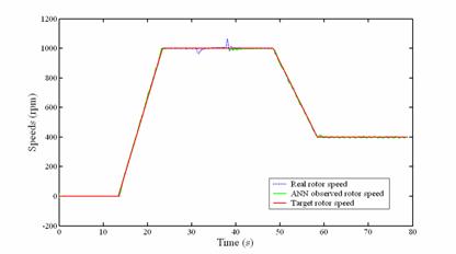
Figure 15. Measured, ANN's observed speeds at variable target speeds under load torque appliance in experimentation
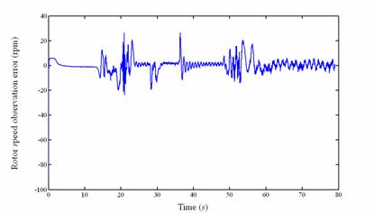
Figure 16. Speed observation error at variable target speeds under load torque appliance in experimentation
Results with Load Applied
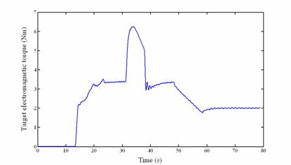
Figure 17. Target electromagnetic torque at variable target speeds under load torque appliance in experimentation
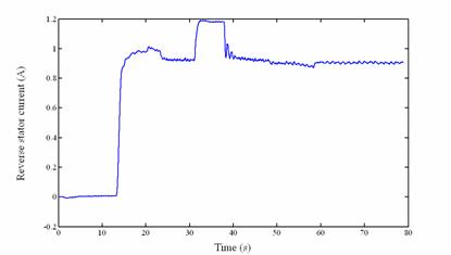
Figure 18. Reverse stator current at variable target speeds under load torque appliance in experimentation
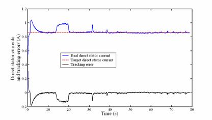
Figure 19. Real and target direct stator currents and tracking error at variable target speeds under load torque appliance in experimentation
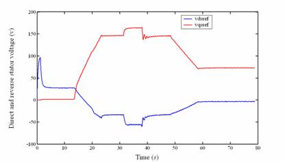
Figure 20. Direct and reverse stator voltage at variable target speeds under load torque appliance in experimentation
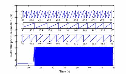
Figure 21. Rotor flux position at variable target speeds under load torque appliance in experimentation
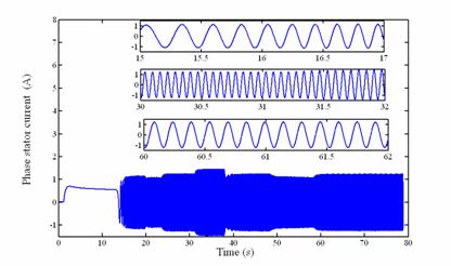
Figure 22. One phase stator current at variable target speeds under load torque appliance in experimentation
Conclusions
In this paper, a neural network speed observer and fuzzy logic speed controller algorithms of a SCIM to increase the speed-sensorless drive performance were proposed. From the experimental results carried on a 1kw induction motor using a dSpace system with DS1104 controller board system based on digital signal processors, it is shown that the proposed algorithms observe and correct respectively the speed over the entire speed range. Also, it has robust speed observation and tracking performances even at load variation or variable-speed operation. Finally, it is confirmed that the proposed speed sensorless vector control algorithm has good dynamic performances and stability.
The most interesting conclusion of all the tests carried out is that the motor response and the one estimated by the net are quite similar, and there is nearly no error in the steady state. That shows the capacity that the model has to generalize and to adapt itself to situations not contemplated in the training phase. In this paper, we are limited to the neural network speed observer and fuzzy logic speed controller. A neural network flux observer and neuro - fuzzy logic flux controller may be a significant prospect for this work.
References
1. Hwan S. and al., Speed Sensorless Vector Control of an Induction Motor Using Neural Network Speed Estimation, IEEE Transaction on Industry Applications, 2001, 48, p. 609-614.
2. Ben Hamed M., Sbita L., Sensorless indirect stator field oriented control of induction motor based on Luenberger observer, The IEEE International Symposium on Industrial Electronics, Montréal-Canada, July 2006.
3. Ben Hamed M., Sbita L., Internal model controller of an ANN speed sensorless controlled induction motor drives, Journal of applied sciences (JAS), 2007, 7(11), p. 1456-1466.
4. Ben Hamed M., Sbita L., Fractional order speed observer for sensorless induction motor drives, International Review of Electrical Engineering (IREE), 2008, 3(1), p. 159-165.
5. Mohanty K.B., Sensorless Control of a Linearized Induction Motor Drive, International Review of Electrical Engineering (IREE), 2007, 2(3), p. 386-397.
6. Messaoudi M., Kraiem H., Kraiem, Ben Hamed M., Sbita L., Abdelkrim M.N., A Robust sensorless direct torque control of induction motor based on MRAS and extended Kalman filter, Leonardo Journal of Sciences (LJS), 2008, 7(12), p. 35-56.
7. Ben Hamed M., Contribution à la Commande Numérique et Synthèse Multi Algorithmiques d'observation du flux et de la vitesse d'un Actionneur à Induction, PhD Thesis, Tunisia Gabes University, 2009.
8. Sbita L., Ben Hamed M., An MRAS - Based Adaptive full order Luenberger observer for sensorless DRFOC of induction motors, International Journal of Automatic Systems and Engineering ( ICGST-ACSE), 2007, 7(1), p. 11-20.
9. Wishart M.T., Harley R.G., Identification and control of induction machines using artificial neural networks, IEEE Transaction on Industry Applications, 1995, 31, p. 612-619.
10. Simoes M.G., Bose B.K., Neural network based estimation of feedback signals for a vector controlled induction motor drive, IEEE Transaction on Industry Applications, 1995, 31, p. 620-629.
11. Teranp T., Asai K., Fuzzy theory and its applications, NewYork, The Academic press Ltd, 1992.
12. Marino P., Milano M., Robust neural network observer for induction motor control, The Annual IEEE Conference on Power Electronics Specialists Conference, 1997.
13. Ben Hamed M., Sbita L., Speed sensorless direct stator field oriented control of induction, The IEEE International Conference on Industrial Technology, Monbey-India, 15-17 December 2006.
14. Caudili M., Millier C., Understanding Neural Networks, Massachusetts, the MIT Press, 1994.
15. Lisboa. P.G.J., Caudili M., Millier C., Neural Networks: Current Applications, London, Chapman & Hall, 1992.
16. Vas P., Artificial intelligence based electrical machines and drives - Application of fuzzy, neural, fuzzy – neural and genetic algorithm based techniques, Oxford university press, 1998.
17. Pinto J., Bode B. K., Borges L. E., Kazmierkowski M. P., A neuronal network based space vector PWM controller for voltage fed inverter induction motor drive, IEEE Transaction on Industry Applications, 2000, 36, p. 1628-1636.
18. Sbita L., Contribution in digital control of systems: Application to digital control of sensorless induction motor drive, dissertation of HDR, National Engineering School of Sfax, Tunisia, p. 153, 2008.
19. Ben Hamed M., Sbita L., Abboud W., Neural Networks for controlled Speed Sensorless Direct Field Oriented Induction Motor Drives, International Journal of Electrical Engineering (JEE ), 2008, 8(11), p. 84-90.
20. Sbita L., Ben Hamed M., Fuzzy controller and ANN speed estimation for induction motor drives, The 4th IEEE International Conference on System, Signals and Devices, 2007.
21. Dreylus G., Martinez J., Samuelides M., Cordan M. B., Thiria S., Hérault L., Neural network: Methodologies and Applications, France, 2002.
22. Mondal S.K., Pinto J.O.P., Bose B.K., A neural network based space vector PWM controller for a three-level voltage-fed inverter induction motor drive, IEEE Transaction on Industrial Electronics Applications, 2002, 38, p. 660-669.
23. Tsoukalas L.H., Uhrig R.E., Fuzzy and neural approaches in engineering, New York Wiley.
24. Sousa G.C.D., Bose B.K., A fuzzy set theory based control of a phase-controlled converter dc drive, IEEE Transaction on Industrial Electronics Applications, 1994, 30, p. 34-44.
25. Sousa G.C.D., Bose B.K., Cleland J.G., Fuzzy logic based on-line efficiency optimization control of an indirect vector controlled induction motor drive, IEEE Transaction on Industrial Electronics, 1995, 42, p. 192-198.
26. Ben Hamed M., Sbita L., Abboud W., Neural Networks for controlled Speed Sensorless Direct Field Oriented Induction Motor Drives, International Journal of Electrical Engineering (JEE ), 2008, 8(11), p. 84-90.