Force Relations and Dynamics of Cutting Knife in a Vertical Disc Mobile Wood Chipper
Segun R. BELLO1, Musiliu A. ONILUDE 2
1Department of Agricultural Engineering Technology, Federal College of Agriculture Ishiagu, Ebonyi State, Nigeria*
2Department of Agricultural and Environmental Engineering, University of Ibadan, Nigeria
E-mail: segemi2002@yahoo.com
*Corresponding Author: Phone: 08068576763
Received: 15 September 2010 / Accepted: 21 June 2011 / Published: 25 June 2011
Abstract
The force relations and dynamics of cutting knife in a vertical disc wood chipper were investigated. The tool geometry determined include: rake angle (20º); Shear angle, (f= 52.15º); the mean frictional angle, (t = 5.71º). The analysis and comparison of the cutting forces has shown that the chips separated from the wood are being formed by off cutting, since normal applied force N is compressive in nature, the magnitude of the forces used by the knife on the wood is expected to increase as the cutting edge of the knife goes deeper into the wood until the value of the resisting force acting against the cut wood Ff is reached and exceeded. The evaluated forces acting on the knife and the chip are: F = 3.63Nmm-1; N = 34.7 Nmm-1; Fs= 27.45Nmm-1; Fn =31.92 Nmm-1; Ft = -8.46Nmm-1; Fc = 33.85Nmm-1. The resultant force acting on the tool face, Pr = 34.89Nmm-1. The specific cutting pressure, Pc and cutting force needed to cut the timber, Fc, are 1.79 × 10⁶ N/m2 and 644.84N respectively. The energy consumed in removing a unit volume of material is 69.96kJ/mm-3 and the maximum power developed in cutting the chip is 3591.77W (4.82hp). The chipper efficiency (86.6%) was evaluated by the highest percentage of accepted chip sizes.
Keywords
Bending load; Capacity; Chipper efficiency; Chute; Cutting energy; Knife angle.
Acceptable chip size range and uniformity of chip thickness constitute performance challenge for chippers [1]. A major chipper performance challenge is to find an optimum combination of chipping speed and knife cutting angles to produce the preferred compromise between pin chip generation and overtrick generation. Chipper performances have been evaluated based on factors such as chipper infeed spout designs, knife and knife holder designs, knife-chip relations and dynamics among others. These factors have been investigated by various researchers in literature [1-6].
Different methods of cutting have been employed in the wood products industry depending on the use of the wood and purpose of operation [2]. In all of these cutting methods, the quality of surface obtained as a result of the process is affected by factors related to the processed material (tree species, quality of materials, moisture contents of the materials, etc.).
The performance of a cutting tool or the machinability of a work material can be evaluated by measuring the cutting forces. There is difference in the cutting forces for parallel, and perpendicular to the fiber axis. This variation makes the study about forces difficult during machining.
Several models have been simulated to study parameters/factors that influence the forces acting on the cutter knife [1, 3-6]. These parameters include; number of cutter knife, cutting angle, bluntness of cutters, etc. and other factors related to the machinery technological level, feeding rate, cutting speed, etc. [2].
In [7] it was identified two cutting directions: longitudinal (90-0) cutting and transversal (90-90) cutting directions where annual rings are orthogonal to the longitudinal side of the piece (Figure 1). These cutting directions obeyed McKenzie’s (1960) notation, where the first number represents the angle in degrees between the cutting edge of the tool and the wood grain, and the second indicates the angle in degrees between the cutting direction and the wood grain.
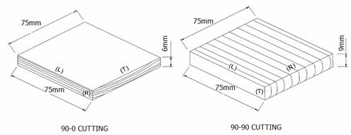
Figure 1. Orientation of specimens according to direction and cutting type (L = longitudinal direction; R = radial direction, and T = tangential direction)
The 90-90 orthogonal cutting is characterized by producing type I and II failures on the machined surface, as well as by high parallel cutting forces compare to 90-0 cutting. In 90-90 cutting, the cutting surface finish is not as important as in the case of 90-0 cutting. On the other hand, the magnitude of the parallel force and the configuration of the cutting tool are, in this case, extremely important [7].
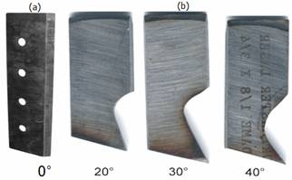
Figure 2. Cutting tools used in the 90-0 cuts (a) and 90-90 (b)
In the 90-0 cutting setting, the positive normal cutting forces indicate that, in relation to the cutting plane, the knife tends to press or penetrate into the specimen. At lower rake angles less than 10°, the normal forces is found to increase as the cutting thickness increases indicating that at small angles the normal force is more significantly influenced by the cutting thickness. At increased rake angles, between 20° and 30°, the mean normal force showed little variation as the wood thickness increased. In 90-90 orthogonal cutting the mean normal force decreased as cutting thickness and angle increased, going from positive to negative between angles of 30° and 40° [7].
Considering all angles, thicknesses, juvenile and mature wood zones, mean cutting forces in the 90-0 cutting direction and the 90-90 cutting direction has been reported. In [7] is reported a cutting forces of 24.63N mm-1 and 35.42N mm-1 for the 90-0 cutting direction and the 90-90 cutting direction respectively. In [8] determined a cutting forces for initial and final Pinus taeda woods under the 90-0 and 90-90 cutting situations, taking into consideration all angles, cutting thicknesses, and initial and final woods, and obtained a mean parallel cutting force values of 22.3N mm-1 for 90-0 cutting, and 34.7 Nmm-1 for 90-90 cutting.
In [9] was determined a cutting forces for three eucalyptus species (grandis, saligna, and citriodora). For the 90-0 cutting of the grandis species, the mean parallel cutting force at the 10° angle, for all thicknesses, was 33.2N mm-1. [7] determined the cutting force for the species Pinus elliottii, in the 90-0 cutting at a 10° angle. The mean parallel cutting force was 27.42 N mm-1 for cutting thicknesses of 0.2 mm; 0.4 mm; and 0.6 mm. For our Pinus taeda, at the same angle and taking the same thickness into consideration, the mean parallel force value was 23.23N mm-1. [10] determined the cutting forces for Pinus radiata and found, for the 90- 0 cutting in the radial direction, taking all cutting thicknesses into consideration, a mean parallel force value of 41.38 N mm-1 at the 20° angle, and 27.88 N mm-1 at the 30° angle.
Chipper Knife & Mounting/Holder
Although chippers vary greatly in size, style, and capacity, the knives they use are all very similar. They are rectangular in shape and are usually 50.8 to 101.6mm (4 to 6 inches) across by 101.6 to 304.8mm (6 to 12 inches) long. They vary in thickness from about 38.1 to 50.8mm (1½ - 2 inches). Chipper knives are made from high grade steel, and usually contain a minimum of 8% chromium hardness [12].
Various knife mounting/holder assemblies have been reported in literatures [11, 12]. An improved, more convenient and simple knife holder design for the chipper eliminates the counter knife and the knife holder with the knife mounted directly on the disc plate by bolts and having an adjacent surface extends outward from the chipper disc at an angle of 120 degrees from the flat surface which abuts the chipper disc [13].
The technical barriers that currently exist in chipping operation include unsuitable chipper cutter (knife type) and mode of feeding during operation. Previously, there has been no major push to develop equipment to overcome these technical barriers in the processing of low value waste wood. Current chipping and re-chipping technologies have served the forest based industries well for many decades; however it is imperative that the force dynamics of these technologies be with the objective of possible modifications to better serve and to be more directly applicable to the end-user needs, either in primary or secondary recovery applications.
Materials and Method
The choice of disc type chipper was due to the inherent high market value advantage of good quality chips produced from disc chippers [14], low initial cost, and the simplicity of the chipping mechanism [15].
Design Considerations
The economic benefits of higher quality chips in pulping have intensified the focus on improving chipper performance. The uniformity of chip size and the percentages of each chip size fraction produced by a chipper are direct functions of knife cutting forces and knife velocity. Other chipper design factors include shaft bending forces, cutting angle and chip geometry. The desire for high quality end-products, machine component reliability and high throughput is balanced by the design and other trade-offs.
Chip Cutting Angle: The logs approach the knives perpendicular to the grain at a 35o spout angle relative to the log axis in order to control chip length while chip thickness remains arbitrary. The chip length is controlled by the distance between the knife cutting edge and the disc plate, i.e. the width of the cutting surface [14].
Chip Size: The desire for good quality chip in pulp industry is a strong factor in the design of chipper machines. Chip size is controlled by knife angle, log orientation and wood grain direction. The range of chip sizes obtainable in chippers include; 25.4-76.2mm (1 to 3 inches) in length, 12.7-25.4mm (1/2 to 1 inches) in width, and (6.25-25.4) mm (¼ - 1 inch) thick [15].
Design Equations and Calculation
The combination of chipper geometry and wood quality will produce a range of chip lengths and thicknesses which may be uniform [16]. Within a given wood species, the combined effects of chip length setting, spout angle, knife edge angle, and knife velocity are primary parameters modified to optimize the relationship between chip length and thickness.
Considering the factors governing the machine performance, the following critical factors are considered in the design of the chipper:
Specific Cutting Force (Fc) Required in Cutting Timber: The specific cutting force required to cut timber into chip is evaluated from the analysis of the forces acting on the wood and the angle of actions, with the following assumptions:
1. An orthogonal cutting situation is assumed in order to determine the specific forces involved in cutting. For the purpose of simplification, the dead weight of the wood is assumed insignificant in relation to the existing forces.
2. The coefficient of shear friction, m is taken as 0.1, which is the smallest value used in simulations [17].
3. An estimated normal cutting force (N) value of 34.7 Nmm-1 at 20° rake angle [7, 18] is used for design calculation.
In the determination of cutting forces, chip thicknesses etc., consideration is given to the dynamics of geometry of cutting. The simulated components of the knife and chip geometry are as shown in Figure 3.

Figure 3. Geometry of cutting angles and force components (where the angle notations in the figure are defined as follows: α = Tool rake angle. A rake angle of 20o is selected; f = Shear angle)
A relationship exists between the shear angle and the rake angle given by the expression:
|
2f + t - α = 90° |
(1) |
m = The coefficient of shear friction = F/N
t = Mean angle of friction between the chip and the tool = tan-1 (F/N)
t1 = (uncut/undeformed chip thickness). This is taken as 0.25 of the maximum wood diameter. t1 is given by
|
t1 = h sin f |
(2) |
t2 = Deformed chip thickness; usually t2 > t1 [18]. t2 is evaluated by the expression
|
t2 = h cos (f-α) |
(3) |
b = Sharpness angle
Action of the knife on the wood is presented with the following force systems analysis indicating forces and angles as drawn in (Figure 4). Applying trigonometry, the forces acting on the knife and the chip is given by the following relationships:
|
F = Ft cos α + Fc sin α |
(4) |
|
N = Fc cos α - Ft sin α |
(5) |
|
Fs = Fc cos f - Ft sinf Fn = Fc sinf - Ft cos f |
(6) (7) |
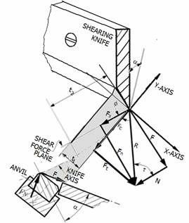
Figure 4. Knife cutting forces and chipping diagram
These forces acts on the wood on the perpendicular and parallel axis to the surface of the knife and are defined as follows:
§ Fc = Force acting in the direction of cutting.
§ Ft = Thrust force needed to keep the tool in the work piece (direction perpendicular to the work piece surface).
§ Pr = Resultant force of Fn and Fs
§ F = Friction force between tool and chip
§ N = Normal force between tool and chip
§ Fs = Shear force with which the knife has to act in order to cause the cutting of the fibres in the wood (it is assumed that this force is perpendicular to the grain).
§ Fn = Force normal to shear plane
Experimentally it has been found that the shear angle and the cutting ratio depend upon the work piece and tool material and the cutting conditions. Several attempts have been made to establish a theoretical law which predicts the shear angle. Ernst and Merchant developed the first reasonable theory. This assumed that the shear angle would take up a value to make the work done in cutting minimum [14]. For given cutting conditions, the work done is proportional to Fc,
Specific Cutting Energy: The specific cutting energy, E is the energy consumed in removing a unit volume of material. Such calculations are required to determine the size of the drive motor. The volume of material removed is V = h w L, so the specific cutting energy can be written as:
|
E = Fc L/h.w.L J/m3, N/ m2, W.s/ m2 |
(8) |
Power Required for Cutting: The power required by each cutting knife was determined using equation 2.
|
Power, W = E Vt/h. |
(9) |
where E = the rate of material removal, Vt = Velocity of knife and h = cutting tool efficiency (typically in the region of 0.7 to 0.8)
Power Consumed in Cutting: The power consumed by the motor in cutting unit fiber of wood subdivision is given by
|
|
(10) |

All units in horsepower (i.e., 1/33000) 1 hp = 0.746 kW
where Pc = The total cutting power (Ps + Pf), Ps = The shearing power required, Pf = The friction losses.
Kinetic Energy of the Rotating Disc: In rotation, a sufficient torque is required to keep the disc spinning at constant angular velocity ω in the absence of resistive force needed to cut the wood. The disc inertia is calculated from the relation
|
I = 0.5 mR2 (kg·m2) |
(11) |
Kinetic Energy of Disc: The disc is a rigid body rotating about a line through the centre of mass and thus possessing a rotational kinetic energy (Er) which is simply the sum of the kinetic energies of its moving parts, and thus it is equal to:
|
Er = 0.5I2 = 0.5I (v/r) 2 |
(12) |
where Er is the kinetic energy in joules, m is the mass in kilograms, ω is angular velocity (v/r) = 20.94 rad·s-1, r is the distance of any mass m from that line, and v is the speed in meters per second.
Power Required to Drive Shaft: Power required to drive the chipper mechanism is given by
|
Pd = F.v = mv3/R |
(13) |
where Pd = power required to drive the chipper disc, F = centripetal force acting on the periphery of the disc = mV2/R, m = Total mass of the chipper unit, R = Radius of disc., V = Disc velocity = pDn, n is given by the ratio of n between the pulley and the disc.
Power required in driving the chipper disc is 14.15kW. According to [20] about 5.22 kW (7 hp) is required to chip an inch of round wood diameter due to the inertia of the heavy rotor. Employing this relation the chipper is designed to chip round wood of approximately (18.97/7) 76.2 mm (3 inches).
The shaft is subjected to two forms of directional loadings: vertical loading and horizontal loading. The Vertical loads resulted from: loads due to weight of pulley acting downward, the applied torque or radial force, loads due to weight of disc and shaft, and reactions at the supports (bearings). The Horizontal loading resulted from; loads due to tangential force exerted by the pulley and reactions at the supports due to the tangential force.
All these forces were resolved by the following equations.
|
RA = √(R2av + R2ah), RA=673.04 N RB = √(R2bv + R2bh), RB=673.04 N TP = √(T2t + M2t), TP=478.91 N RA+RB=TP + Wr Wr = 673.04+497.15-478.91 = 298.39 N |
(14) |
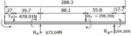
Figure 6. Resultant loading forces on shaft
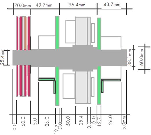
Figure 5. Shaft profile and dimensions
Bending Moment Equations
The bending forces at each point load is evaluated by the following moment equations
|
|
(15) |

The free body diagram (FBD), shear force diagram (SFD) and bending moment diagrams (BMD) are shown in Figure 5 below. The maximum bending moment MB max as evaluated from equation 15 is + 21.25 Nm. This occurs within the region of the chipper disc, WR indicating the area of highest load concentration.
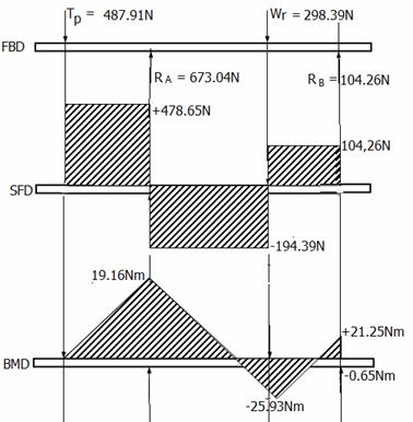
Figure 5. Force distribution diagram on the shaft (*FBD = Free body Diagram; SFD = Shear Force Diagram; BMD = Bending Moment Diagram)
To increase safety in solid shaft, the maximum bending moment MB max is multiplied by a factor of 1.6; MB max = 21.25 × 1.6 = 34.00 Nm
Equivalent moment of the forces Meq is given by [17]
|
Meq = √(T2m+M2Bmax) |
(16) |
where Tm = Torsional moment in shaft (30.52 Nm, calculated in equation 16); Meq = Equivalent moment (45.69 Nm).
The shaft diameter that will withstand these loads is calculated from the maximum shear stress theory and the combined stress equation is used thus
|
πds3/16 = √[(T2mx+M2max)/Sall] |
(17) |
where Tmax = maximum torsional (twisting) moment; MBmax = Maximum bending moment; Sall = Allowable design shear stress = 3.7921 × 10⁷ N/m2; ds = shaft diameter (0.018m) determined from equation (21). If a safety factor of 1.3 is assumed for the design the shaft diameter is 1.5 × ds. Any shaft diameter below this value (27.0mm) will fail through bending. From shaft standard table, a shaft diameter of 38.1 mm is selected for safe shaft design.
Strength in shaft is determined to know the limit to which bending will be prevented in the shaft. Bending stress eqn. is given by
|
B.S. = Bending load / Area of cross section of the shaft |
(18) |
where Bending stress σ, for steel = 10,000psi (1psi =0.07 kg/cm2), Bending load = weight of shaft + Disc + torsional force + weight of pulley.
Area of cross section = pD2 /4. D is the calculated Ds
Rigidity (Torsional Deflection) in Shaft
Angle of twist in shaft as a result of torsion is expressed by the expression below with an assumption that torque is constant within limits of each shaft step
|
|
(19) |
where qt = Angle of twist as a result of torsion. This should be within the acceptable value range of 0o – 5o; Mt = Critical torque applied to the shaft; Jti = Polar moment of inertia of shaft (cm4) = pds4/32; G = Shear modulus or modulus of rigidity (8.1 x 10¹⁰ Nm2 for steel); li = Shaft length; Stiffness factor Ct = Mt/Θt
|
Yield factor ƒ = 1/Ct |
(20) |
For torsional load, torsional stress is given by
|
τxy = 16mt / πd3 |
(21) |
Bending stress
|
σb = mbr /I =32mb /d3 |
(22) |
Axial stress load
|
σa =4Fa /d3 |
(23) |
Stress concentration factor is calculated from the ratio of the maximum load stress to the rated stress found in the elastic zones.
|
ασ = σmax / σrated and ατ = τmax / τrated , ασ = 1 |
(24) |
General Machine Description and Fabrication
The chipper consists of a chipper disc assembly, frame, a disc housing, an infeed chute and an exhaust or discharge chute. The disc chipper employs a rotary cutting steel disc secured to a shaft and simply supported on friction bearings to cut wood into chips. The cutting disc is formed from mild steel 25.4mm (1’) thick. There are 3 cutting knives; 200mm in length fixed to the cutting sides of the disc bolted directly to the rotating disc.
Machine components and shapes were produced from secondary machining operations including cutting, grinding, and trimming, drilling, sawing, and turning. The conditions of tools used for machining has greater influence on component performance, hence adequate care was taken to establish and maintain the optimum tool conditions.
At the correct working level position, the height of the lower edge of the infeed chute is 1000 mm from the ground level; the horizontal distance from the spout opening to the shortest part of the chute outer edge (below 1000 mm) from the ground is 1200 mm [21].
The dimensions of the infeed chute are designed to give protection against both upper and lower limbs from being pulled into the machine. It is equally important to ensure that the chute is long enough to prevent hands reaching the chipper knives. The lower edge of the infeed chute selected for the design is 600 mm considering the ability of the operator to bend at the hips. In this configuration, the chipper is fitted with a spout that approaches the disc at an angle of about 38 to 42 degrees from the vertical plane.
Performance Tests
Several samples of chips were randomly taken from the chipped material at various points and time intervals. The materials were sorted on a table and classified based on sums of average of sampled chips in accordance with TAPPI 257 “Sampling and Preparing Wood for Analysis” strategy SCAN-CM 40:01 classification reported by [22].
Results and Discussions
The fabricated machine is as shown in Figure 6 while Table 1 gives the summary of the designed machine specifications. Most available commercial mobile wood chippers have the same range of dimension and the specifications compare favourably with most commercially available mobile disc chippers [21, 22].
Tool Geometry and Cutting Forces
Based on design calculations, the tool geometry determined include: the selected rake angle, α of 20o; Shear angle, f= 52.15o (calculated) to minimize work done in cutting; The mean angle of friction,t = 5.71o (calculated); The chip length, h (calculated) at any given set of knife angle is 24.13mm; The average thickness (t mm) of the chips produced (19.05-20.43) mm. The forces acting on the knife and the chip evaluated from equations 4- 7 are: F = 3.63Nmm-1; N = 34.7 Nmm-1; Fs= 27.45Nmm-1; Fn =31.92 Nmm-1; Ft = -8.46Nmm-1; Fc = 33.85Nmm-1. The resultant force acting on the tool, Pr = 34.89Nmm-1, is made up of a normal force, N acting perpendicular to the tool face and F the friction force acting along the face.
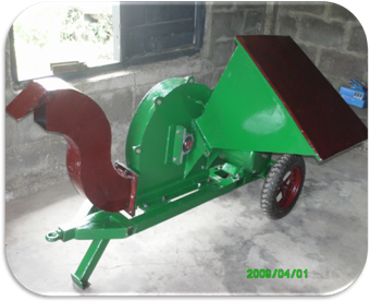
Figure 6. The mobile wood chipper
Table 1. Machine Specifications
|
Components |
Specifications |
|
Engine: |
Atlas 3-phase double winding 15hp synchronous electric motor Speed: 1440rpm, voltage 1.2v, frequency; 50Hz |
|
Infeed Chute: |
Chute opening at chipper disc; w180mm × h150mm /w450mm × h360mm at feed point |
|
Discharge Chute |
Discharge chute: provided with directional flip cover. 900mm from wheel |
|
Chipper Disc: |
Disc Size: 1100mm x 60mm, Disc Weight: 86kg, Disc Speed: 540 rpm |
|
Knives: |
Three knives made of hardened spring steel. 190mm x 76mm x 10mm double edged, reversible and re-sharpen able. |
|
Drive Belts: |
Industrial "V" B51/5L540 (two) |
|
Anvil: |
Made from hard wearing metal with easy external adjustment |
|
Infeed Roller: |
38.2mm diameter steel roller, in-between the anvil and the knives |
|
Chipper Housing |
12mm plate front and back, 6mm plate disc cover. |
|
Chip thrower |
Minimum feed rate approximately 80 feet per minute. |
|
Frame Support: |
The frame is a network of angle iron and squared pipes welded together. |
|
Land wheels: |
Wheels 15 x 6.00 |
|
Machine Capacity |
76mm (3 inch) – rated to 3 inches whole log |
The analysis and comparison of the cutting forces has shown that the chips separated from the wood are being formed by off cutting [22], since normal (usual) force N is compressive in nature, the magnitude of the forces used by the knife on the wood is expected to increase as the cutting edge of the knife goes deeper into wood up to the moment when the value of the resisting force against wood cutting Ff is reached and exceeded. Then the wood breakage takes place and the separated part of wood (chip) is shifted and comes off the rest of the wood. This result is in agreement with those of [22].
The nominal cutting stress (specific cutting pressure), Pc and cutting force needed to cut the timber, Fc, evaluated are 1.79 × 10⁶ (N/m2) and 644.84N respectively. The energy consumed in removing a unit volume of material (The specific cutting energy) given by equation (10) is 69.96kJ/mm-3 and the maximum power developed in cutting the chip is 3591.77W (4.82hp)
Performance Test
The ergonomic properties of the machine conform to the set standard A38 standard. The overall height of machine is adequate considering the bending and feeding of the machine with the average height of man, 1.6m. Outer edge opening of the infeed chute is a minimum of 41” wide × 39” high. Opening at feed spout is designed to be a minimum of 14” wide × 12” high. The external length from feed spout to ground level is 85’.
The chip classification and mean distribution of chip sizes has been presented by [21]. The chip particles seen in these samples are broadly characterized as coarse and fibrous in nature. The coarse characteristic refers to the irregular surface geometry produced by the blunt force reduction action of the chipping process. The fibrous characteristic refers to the way the particles have separated with the longitudinal grain of the wood and the frayed ends of each particle. Figure 7 shows the range of physical characteristics of chip classes and sizes produced by the machine.
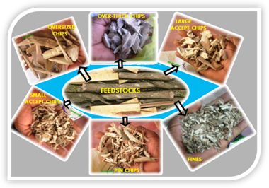
Figure 7. Chip samples classified
Dominance of one single class might be very difficult to obtain, especially when the chips were produced from delimbed logs; the presence of knots and other impurities introduce such variance.
This study has identified operating parameters to be considered in developing appropriate size reduction strategies for wood waste recovery. The potential effect of tool dynamics and cutting forces on chip properties was estimated using appropriate equations and assumptions. The chip size classification was used as a basis for validating the equations and formulas employed in the design.
From the test results, the machine performed its designed functions and meets the commercial chipper specifications of producing good quality chips with no dust and less fines. The chipper efficiency was evaluated by the highest percentage of accepted chip sizes (86.6 %). The disc chipper offers the largest particles and the highest size consistency. The dust-free chip produced by the machine is very regular, but it might prove too large for some conversion plants.
References
1. Kline W.A., DeVor R.E., Lindberg J.R., The Prediction of Cutting Forces in End Milling with Application to Cornering Cuts, Int. J. Mach. Tool Des. Res., 1982, 22(1), p. 7-22.
2. Sutherland J.W., DeVor R.E., An Improved Method for Cutting Force and Surface Error Prediction in Flexible End Milling Systems. Journal of Engineering for Industry, 1986, 108, p. 269-279.
3. Lauderbaugh L.K., Ulsoy A.G., Dynamic Modeling for Control of the Milling Process, Journal of Engineering for Industry, 1988, 110, p. 367-375.
4. Montgomery D. Altintas Y., Mechanism of Cutting Force and Surface Generation in Dynamic Milling, Journal of Engineering for Industry, 1991, 113, p. 160-168.
5. Tlusty J. S.S., An Overview of Modeling and Simulation of the Milling Process, Journal of Engineering for Industry, 1991, 113, p. 169-175.
6. Wen-Hsiang Lai, Modeling of Cutting Forces in End Milling Operations, Tamkang Journal of Science and Engineering, 2000, 3(1), p. 15-22.
7. Gonçalves R., Néri A. C., Orthogonal cutting forces in juvenile and mature pinus taeda wood, Sci. Agric. (Piracicaba, Braz.), 2005, 62(4), p. 310-318.
8. Woodson G.E., Koch P., Tool forces and chip formation in orthogonal cutting of loblolly pine, Washington: USDA, Forest Service,. (Research Paper SO, 52) 1970.
9. Néri A.C., Gonçalves R.; Hernandez R.E., Forças de corte ortogonal 90-0 em três espécies de madeira de eucalipto, Revista Brasileira de Engenharia Agrícola e Ambiental, 1999, 3, p. 239-244.
10. Toro W.M., Lara C.M.; Mac-Carte G.V., Estimacion ymodelamiento estadistico para la fuerza resultante de corte 90-0 em madera de Pinus radiata. In: congresso ibero-americano de pesquisa e desenvolvimento de produtos florestais, Curitiba, 2002.
11. Stringer E.G., Knife Holder for Wood Chippers. Can. pat. 1, 262, 622, 1989, 7(7), p. 1-9. 4 claims. 15 p. Cl.29-36. Filed: Can. appln. 512, 65.
12. Kawasaki B.O.M., The effect of cutting speed on the surface quality in wood cutting - Model experiments and simulations by the extended distinct element method. 12th International Wood Machining Seminar, 1995, p. 56-62.
13. Stringer E. G., Knife Holder for Wood Chippers. US Pat. 4712597, 1987, 15, 4 claims Filed: Mar, 27, 1986 US Cl. 144/176; 144/162R
14. CWC, Wood Waste Size Reduction Technology Study 1997, NIST MEP Environmental program (# CDL-97-3) www.cwc.org (Accessed 07/01/2009).
15. Timothy M. Maker, Wood-Chip Heating Systems. A Guide for Institutional and Commercial Biomass Installations, Revised by Biomass Energy Resource Center Montpelier, Vermont, 2004.
16. Valby, The effects of chip size on mechanical pulp properties and energy consumption, Tappi Journal, September, 1983, 66(9), p. 119-122.
17. Hugh Jack, Engineer on disc. http://claymore.engineer.gvsu. edu/eod/global/copyrght.html. © 1993-2001, Hugh Jack. (Accessed 30/05/2008).
18. Dobrovolski V., Zablousky K., Mak S., Radchik A., Erlich L., Machine Element. A Textbook 2nd Ed. Mir Pub. Moscow, 1974.
19. Wikimanual, Garden tools. Wood chipper from the open-content textbooks collection. Retrieved from http://en.wikibooks.org, 2007 (Accessed 07/01/2009).
20. Brill J., Effects of wood and chip quality on TMP properties, International Mechanical Pulping Conference, proceedings, SPCI Stockholm, 1985, p. 153-161.
21. Spinelli R., Hartsough B.R., Magagnotti N. Testing Mobile Chippers for Chip Size Distribution, International Journal of Forest Engineering. http://www.lib.unb.ca/Texts/JFE/July05/spinelli.pdf (Accessed 03/08/2008).
22. Kawka W., Ingielewicz H., Wróblewski T., Research studies on the drum chippers RB-800, RB-1300 and other scientific and research works. Typescript. Institute of Papermaking and Printing, Technical University of Łodź, 1987-1997.