Adaptive Neuro-Fuzzy Inference System based DVR Controller Design
Samira DIB, Brahim FERDI*, Chellali BENACHAIBA
Faculty of the sciences and technology, Department of Technology, Bechar University
B.P 417 BECHAR (08000), Algeria
E-mail: ferdi_brahim@yahoo.com
* Corresponding author: Phone: (213) 0558111227
Received: 8 October 2010 / Accepted: 13 May 2011 / Published: 25 June 2011
Abstract
PI controller is very common in the control of DVRs. However, one disadvantage of this conventional controller is its inability to still working well under a wider range of operating conditions. So, as a solution fuzzy controller is proposed in literature. But, the main problem with the conventional fuzzy controllers is that the parameters associated with the membership functions and the rules depend broadly on the intuition of the experts. To overcome this problem, Adaptive Neuro-Fuzzy Inference System (ANFIS) based controller design is proposed. The resulted controller is composed of Sugeno fuzzy controller with two inputs and one output. According to the error and error rate of the control system and the output data, ANFIS generates the appropriate fuzzy controller. The simulation results have proved that the proposed design method gives reliable powerful fuzzy controller with a minimum number of membership functions.
Keywords
Dynamic Voltage Restorer (DVR); Sugeno Fuzzy Controller; Adaptive Neuro-Fuzzy Inference System (ANFIS); Voltage Sag; Voltage Swell; Voltage Unbalance.
Introduction
Due to the increased use of a large numbers of sophisticated electrical and electronic equipment, such as computers, programmable logic controllers, variable speed drives, and so forth, proliferation of highly sensitive end-user devices is starting to draw attention of both end customers and suppliers to the question of power quality [1]. Faults at either the transmission or distribution level may cause voltage sag or swell in the entire system or a large part of it. Also, under heavy load conditions, a significant voltage drop may occur in the system. Voltage sags can occur at any instant of time, with amplitudes ranging from 10 - 90% and a duration lasting for half a cycle to one minute [2]. Further, they could be either balanced or unbalanced, depending on the type of fault and they could have unpredictable magnitudes, depending on factors such as distance from the fault and the transformer connections. Voltage swell, on the other hand, is defined as a sudden increasing of supply voltage up 110% to 180% in RMS voltage at the network fundamental frequency with duration from half a cycle to 1 minute [2]. Voltage swells are not as important as voltage sags because they are less common in distribution systems. Voltage sag and swell can cause sensitive equipment (such as found in semiconductor or chemical plants) to fail, or shutdown, as well as create a large current unbalance that could blow fuses or trip breakers. These effects can be very expensive for the customer, ranging from minor quality variations to production downtime and equipment damage [3]. There are many different methods to mitigate voltage sags and swells, but the use of a DVR is considered to be the most cost efficient method [3].
The most common choice for the control of the DVR is the so called PI controller since it has a simple structure and it can offer relatively a satisfactory performance over a wide range of operation. The main problem of this simple controller is the correct choice of the PI gains and the fact that by using fixed gains, the controller may not provide the required control performance, when there are variations in the system parameters and operating conditions. To solve these problems fuzzy logic control appears to be the most promising, due to its lower computational burden and robustness. Also, a mathematical model is not required to describe the system in fuzzy logic based design. But, the main problem with the conventional fuzzy controllers is that the parameters associated with the membership functions and the rules depend broadly on the intuition of the experts. If it is required to change the parameters, it is to be done by trial and error only. There is no scientific optimization methodology inbuilt in the general fuzzy inference system [4]. To overcome this problem, Adaptive Neuro-Fuzzy Inference System (ANFIS) is used. In ANFIS, the parameters associated with a given membership function are chosen so as to tailor the input/output data set.
This paper introduces Dynamic Voltage Restorer (DVR) and its operating principle, also presents the proposed Sugeno fuzzy controller which was generated using ANFIS method design. Then, simulation results using MATLAB-SIMULINK were illustrated and discussed.
Dynamic Voltage Restorer (DVR)
A Dynamic Voltage Restorer (DVR) is a series connected solid state device that injects voltage into the system in order to regulate the load side voltage. The DVR was first installed in 1996 [4]. It is normally installed in a distribution system between the supply and the critical load feeder. Its primary function is to rapidly boost up the load-side voltage in the event of a disturbance in order to avoid any power disruption to that load [6]. There are various circuit topologies and control schemes that can be used to implement a DVR [7, 8]. In addition to its main task which is voltage sags and swells compensation, DVR can also added other features such as: line voltage harmonics compensation, reduction of transients in voltage and fault current limitations [9]. The general configuration of the DVR consists of a voltage injection transformer, an output filter, an energy storage device, Voltage Source Inverter (VSI), and a Control system as shown in Figure 1.
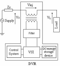
Figure 1. DVR general configuration
Voltage Injection Transformer
The basic function of this transformer is to connect the DVR to the distribution network via the HV-windings and couples the injected compensating voltages generated by the voltage source converters to the incoming supply voltage. The design of this transformer is very crucial because, it faces saturation, overrating, overheating, cost and performance. The injected voltage may consist of fundamental, desired harmonics, switching harmonics and dc voltage components. If the transformer is not designed properly, the injected voltage may saturate the transformer and result in improper operation of the DVR [10].
Output Filter
The main task of the output filter is to keep the harmonic voltage content generated by the voltage source inverter to the permissible level (i.e. eliminate high frequency switching harmonics).It has a small rating approximately 2% of the load VA [11].
Voltage Source Inverter
A VSI is a power electronic system consists of switching devices (IGCTs, IGBTs, GTOs), which can generate a sinusoidal voltage at any required frequency, magnitude, and phase angle. In the DVR application, the VSI is used to temporarily replace the supply voltage or to generate the part of the supply voltage which is missing [12].
DC Energy Storage Device
The DC energy storage device provides the real power requirement of the DVR during compensation. Various storage technologies have been proposed including flywheel energy storage [13], super-conducting magnetic energy storage (SMES) [14] and Super capacitors [15, 16]. These have the advantage of fast response. An alternative is the use of lead-acid battery [17, 18]. Batteries were until now considered of limited suitability for DVR applications since it takes considerable time to remove energy from them [19]. Finally, conventional capacitors also can be used [20, 21].
Control System
The aim of the control system is to maintain constant voltage magnitude at the point where a sensitive load is connected, under system disturbances. The control system of the general configuration typically consists of a voltage correction method which determines the reference voltage that should be injected by DVR and the VSI control which is in this work consists of PWM with PI controller. The controller input is an error signal obtained from the reference voltage and the value of the injected voltage (Figure 2). Such error is processed by a PI controller then the output is provided to the PWM signal generator that controls the DVR inverter to generate the required injected voltage.
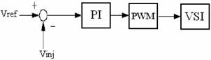
Figure 2. Classical PI controller
Operating Principle of DVR
The basic function of the DVR is to inject a dynamically controlled voltage Vinj generated by a forced commutated converter in series to the bus voltage by means of a voltage injection transformer. The momentary amplitudes of the three injected phase voltages are controlled such as to eliminate any detrimental effects of a bus fault to the load voltage VL. This means that any differential voltages caused by disturbances in the ac feeder will be compensated by an equivalent voltage. The DVR works independently of the type of fault or any event that happens in the system. For most practical cases, a more economical design can be achieved by only compensating the positive and negative sequence components of the voltage disturbance seen at the input of the DVR (because the zero sequence part of a disturbance will not pass through the step down transformer which has infinite impedance for this component).
The DVR has two modes of operation which are: standby mode and boost mode. In standby mode (Vinj=0), the voltage injection transformer’s low voltage winding is shorted through the converter. No switching of semiconductors occurs in this mode of operation, because the individual inverter legs are triggered such as to establish a short-circuit path for the transformer connection. The DVR will be most of the time in this mode. In boost mode (Vinj>0), the DVR is injecting a compensation voltage through the voltage injection transformer due to a detection of a supply voltage disturbance.
Voltage Reference Calculation Method
There are lots of methods for DVR voltage correction generating reference voltage that DVR must inject it into the bus voltage [22-27]. The strategy of voltage reference calculation used in this work is shown in Figure 3.
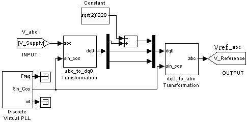
Figure 3. SIMULINK model of SRF method for voltage reference calculation
Figure 3 shows the basic control scheme and parameters that are measured for control purposes. When the supply voltage is at its normal level the DVR is controlled to reduce the losses in the DVR to a minimum. When voltage sags/swells are detected, the DVR should react as fast as possible and inject an ac voltage into the grid. It can be implemented using the synchronous reference frame (SRF) technique based on the instantaneous values of the supply voltage. The control algorithm produces a three phase reference voltage to the PWM inverter that tries to maintain the load voltage at its reference value. The voltage sag/swell is detected by measuring the error between the d-voltage of the supply and the d-reference value. The d-reference component is set to a rated voltage. The MATLAB/Simulink environment is a useful tool to implement this method (SRF) because it has many tool boxes that can be used easily. The SRF method can be used to compensate all type of voltage disturbances, voltage sag/swell, voltage unbalance and harmonic voltage, but in this work we have studied only voltage sag/swell. The difference between the reference voltage and the injected voltage is applied to the VSI to produce the load rated voltage, with the help of pulse width modulation (PWM) through the PI controller.
ANFIS based controller design
This section introduces the basics of ANFIS network architecture and its hybrid learning rule. Inspired by the idea of basing the fuzzy logic inference procedure on a feed forward network structure, Jang [29] proposed an Adaptive Network-based Fuzzy Inference System (ANFIS) or semantically equivalently, the Adaptive Neural Fuzzy Inference System, whose architecture is shown in Figure 4. He reported that the ANFIS architecture can be employed to model nonlinear functions, identify nonlinear components on-line in a control system, and predict a chaotic time series.
It is a hybrid neuro-fuzzy technique that brings
learning capabilities of neural networks to fuzzy inference systems. The
learning algorithm tunes the membership functions of a Sugeno-type Fuzzy
Inference System using the training input-output data. The ANFIS is, from the
topology point of view, an implementation of a representative fuzzy inference
system using a back propagation (BP) neural network-like structure. It consists
of five layers. The role of each layer is briefly presented as follows: let ![]() denote the output of node i in
layer l, and xi is the ith input of
the ANFIS, i = 1, 2,...,p. In layer 1, there is a node function M
associated with every node:
denote the output of node i in
layer l, and xi is the ith input of
the ANFIS, i = 1, 2,...,p. In layer 1, there is a node function M
associated with every node:
|
|
(1) |
The role of the node functions M1, M2 ...Mq here is equal to that of the membership functions μ(x) used in the regular fuzzy systems, and q is the number of nodes for each input. Gaussian shape functions are the typical choices. The adjustable parameters that determine the positions and shapes of these node functions are referred to as the premise parameters. The output of every node in layer 2 is the product of all the incoming signals:
|
|
(2) |
Each node output represents the firing strength of the reasoning rule. In layer 3, each of these firing strengths of the rules is compared with the sum of all the firing strengths. Therefore, the normalized firing strengths are computed in this layer as:
|
|
(3) |

Layer 4 implements the Sugeno-type inference system, i.e., a linear combination of the input variables of ANFIS, x1, x2, ...xp plus a constant term, c1, c2, ...,cp, form the output of each IF −THEN rule. The output of the node is a weighted sum of these intermediate outputs:
|
|
(4) |
where parameters P1, P2, ...,Pp and c1,c2, ...,cp, in this layer are referred to as the consequent parameters. The node in layer 5 produces the sum of its inputs, i.e., defuzzification process of fuzzy system (using weighted average method) is obtained:
|
|
(5) |
The flowchart of ANFIS procedure is shown in Figure 5. ANFIS distinguishes itself from normal fuzzy logic systems by the adaptive parameters, i.e., both the premise and consequent parameters are adjustable. The most remarkable feature of the ANFIS is its hybrid learning algorithm. The adaptation process of the parameters of the ANFIS is divided into two steps. For the first step of the consequent parameters training, the Least Squares method (LS) is used, because the output of the ANFIS is a linear combination of the consequent parameters. The premise parameters are fixed at this step. After the consequent parameters have been adjusted, the approximation error is back-propagated through every layer to update the premise parameters as the second step. This part of the adaptation procedure is based on the gradient descent principle, which is the same as in the training of the BP neural network. The consequence parameters identified by the LS method are optimal in the sense of least squares under the condition that the premise parameters are fixed [30].
Figure 4. Structure of ANFIS
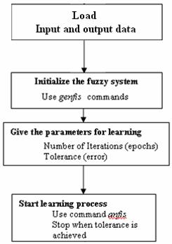
Figure 5. ANFIS procedure
The MATLAB/SIMULINK implementation of the Sugeno fuzzy controller for one phase is shown in figure 6.
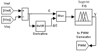
Figure 6. SIMULINK model of the proposed controller
Simulation Results and Discussions
The input-output data pairs for training the ANFIS were generated using the conventional PI controller. ANFIS structure with Sugeno model containing 9 rules (Tables I) have been considered. Hybrid learning algorithm method was used to adjust the parameter of membership function. All the variables’ fuzzy subsets for the inputs ε and ∆ε are defined as (M1, M2, M3) with triangular membership function. The membership functions and initial universes of the inputs generated by ANFIS training are illustrated in Figure 7 and 8. The output variable Y given by ANFIS training is a vector of constants. Y= [y1, y2, y3, y4, y5, y6, y7, y8, y9] where, y1=-1397, y2=-1397, y3=-1397, y4=-38.58, y5=-38.58, y6=-38.58, y7=1319, y8=1320, y9=1320. The control rules are illustrated in Table 1.
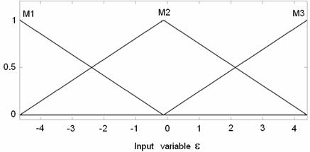
Figure 7. Membership function curves of the inputs ε
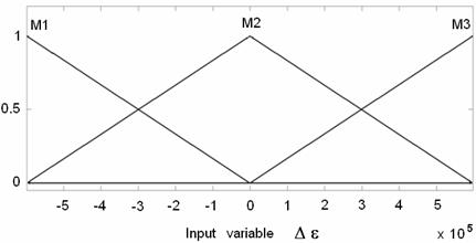
Figure 8. Membership function curves of the input ∆ε
Table 1. Fuzzy control rules
|
ε / ∆ε |
M1 |
M2 |
M3 |
|
M1 |
y1 |
y2 |
y3 |
|
M2 |
y4 |
y5 |
y6 |
|
M3 |
y7 |
y8 |
y9 |
A DVR is connected to the system through a series transformer with a capability to insert a maximum voltage of 80% of the phase to ground system voltage. In the following simulations, the main characteristics of the DVR are set as: voltage source full-bridge IGBT based inverter controlled with PWM signal generator with commutation frequency of 12kHz, capacitor energy storage bank 8.8 mF, coupling transformer ratio 1:1, nominal dc link voltage 850V, LC output filter values C=80 µF in series with a damping resistance Rd = 0.1 Ω, L = 1 mH, source voltage 220Vrms and source frequency of 50 Hz. The load is 80 kVA with 0.92 p.f., lagging. The tuning of the PI is made such to have high transient speed and to have very low tracking error for the fundamental (50 Hz), with Kp = 250 and Ki = 135.
A case of Three-phase 50% balanced voltage sag is simulated and the result is shown in Figure 9. Voltage sag is initiated at 200 ms and it is kept until 300 ms, with total voltage sag duration of 100ms. As a result of the control of DVR by the proposed fuzzy controller; the load voltage is kept at 1.00 p.u throughout the simulation, including the voltage sag period. We can notice that during normal operation, the DVR is doing nothing but once voltage sag is detected, it quickly injects necessary voltage components to smooth the load voltage.
Figure 9. Simulation result of DVR response to a balanced voltage sag
Figure 10. Simulation result of DVR response to a balanced voltage swell
Figure 11. Simulation result of DVR response to unbalanced voltages
For the case of balanced voltage swell compensation represented by Figure 10, the load voltage is kept at the nominal value with the help of the DVR. Similar to the case of voltage sag, the DVR reacts quickly to inject the appropriate voltage component (negative voltage magnitude) to correct the supply voltage.
At the end Three-phase unbalanced voltages condition is investigated to confirm the performance of the DVR under the proposed fuzzy controller. According to figure 11, the DVR is able to produce the required voltage components for different phases rapidly and help to maintain a balanced and constant load voltage at 1.00pu. As a result, the performance of DVR under the proposed fuzzy controller in mitigating voltage sags/swell and voltage unbalance is evident. In addition the proposed fuzzy controller has the minimum number of membership functions for the inputs (3) and do not need gains which make its implementation practically very easy with a minimum cost.
Conclusions
DVRs are effective custom power devices for voltage sags and swells mitigation. They inject the appropriate voltage component to correct rapidly any anomaly in the supply voltage to keep the load voltage balanced and constant at the nominal value. In the present paper a reliable controller with high performance for dynamic voltage restorers was proposed. The proposed controller is generated by ANFIS training according to a given input output data. Compared to the traditional fuzzy controller, the proposed one is the simplest (9 rules only) and the most cost efficient controller. In addition this controller has no gains to adjust and solve the problem of traditional fuzzy controller gains tuning.
References
2. IEEE Std. 1159 - 1995, Recommended Practice for Monitoring Electric Power Quality.
3. Youssef K., Industrial power quality problems Electricity Distribution, IEE Conf. Pub1 No. 482, 2001, 2, p. 5.
4. Li B. H., Choi S.S., Vilathgamuwa D. M., Design considerations on the line-side filter used in the dynamic voltage restorer, IEE Proceedings - Generation, Transmission, and Distribution, 2001, 148, p. 1-7.
5. Mitra P., Maulik S., Chowdhury S.P., Chowdhury S., ANFIS Based Automatic Voltage Regulator with Hybrid Learning Algorithm, International Journal of Innovations in Energy Systems and Power, 2007, 3(2), 397-401.
9. Young-Hoon Cho, Seung-Ki Sul., Controller Design for Dynamic Voltage Restorer with Harmonics Compensation Function, Industry Applications Conference, 2004. 39th IAS Annual Meeting. Conference Record of the 2004 IEEE, 7 Oct. 2004, 3(3), p. 1452 - 1457.
10. Mahesh S.S., Mishra M.K., Kumar B.K., Jayashankar V., Rating and Design Issues of DVR Injection Transformer, Applied Power Electronics Conference and Exposition (APEC) 2008. Twenty-Third Annual IEEE, Austin, TX, p. 449-455.
12. Bollen M.H.J., Understanding Power Quality Problems, New York: IEEE Press, 2000
23. Singh B, Jayaprakash P, Kothari D P, Chandra A, Kamal-Al-Haddad., Indirect Control of Capacitor Supported DVR for Power Quality Improvement in Distribution System, Power and Energy Society General Meeting - Conversion and Delivery of Electrical Energy in the 21st Century, 2008 IEEE, 20-24 July 2008, p. 1-7.
24. Meyer C., Romaus C., De Doncker R. W., Optimized Control Strategy for a Medium-Voltage DVR, 36th IEEE Power Electronics Specialists Conference (PESC), 16-16 June 2005, p. 1887-1893.
25. Hyosung Kim, Sang-Joon Lee, Seung-Ki Sul., A Calculation for the Compensation Voltages in Dynamic Voltage Restorers by use of PQR Power Theory, Applied Power Electronics Conference and Exposition (APEC) , Nineteenth Annual IEEE, 2004, 1, p. 573-579.
26. Ming Hu, Heng Chen, Modeling and Controlling of Unified Power Quality Component, in APSCOM-00, 2000, 2, p. 431-435.
27. Liu J.W., Choi S.S., Chen S., Design of Step Dynamic Voltage Regulator for Power Quality Enhancement, IEEE Transactions on Power Delivery, 2003, 18, p. 1403-1409.
28. Boonchiam P., Mithulananthan N., Understanding of Dynamic Voltage Restorers Through MATLAB Simulation, Thammasat Int. J. Sc. Tech., 2006, 11(3), Available at: http://www.tijsat.tu.ac.th/issues/2006/no3/2006_V11_No3_1.PDF (Accessed January 2010).