Code Recognition Device for Automobile, a Panacea for Automobiles Theft
Ozomata David AHMED
Department of Electrical and Electronics Engineering, School of Engineering and Engineering Technology, Federal University of Technology, Minna, Niger State, Nigeria
E-mail: ahmedozomata@yahoo.com
* Corresponding author: Phone: +234(0)8054194081
Received: 23 August 2010 / Accepted: 13 May 2011 / Published: 25 June 2011
Abstract
Code Recognition Device is a security device for automobiles. It responds only to the right sequence of codes that are keyed from the key pad. This closes the electrical circuitry of the automobile and enables it to start. If a wrong key is touched, it resets the device which disengages the electrical circuit of the automobile from the power supply. The device works properly on closing all the doors of the automobile, otherwise it cannot start. Also, once the automobile is in operation, opening of any door will disengage the device and the engine will stop. To restart the engine, the doors must be closed and the codes rendered sequentially-in this case the codes are 1974.
Keywords
Automobile; D Flip-Flop; Security Systems; Code Recognition.
Introduction
Technology has played a vital role in the revolution of automobiles. Automobiles today are far superior than they ever were. They offer both increased performance and better economy from the same sized engines. They are safer both for the occupants and other road users, less polluting and vastly better equipped. The car has also had huge impacts on our society; influencing factors such as how often we go to the beach, to the structuring of entire cities [1]. In many respects the modern automobile is seen by many as integral part of our everyday life.
The widespread popularity of automobiles can partly be attributed to the increasing levels of disposable income and plummeting automobile prices. Once seen only as luxury items of the rich, automobiles have now become affordable to most working class citizens. The vast market for automobiles has also spawned a secondary automobile customization and accessories industry.
In some cases, the accessories on an automobile are worth more than the vehicle itself! Unfortunately, this huge demand for automobiles and their respective accessories has given rise to a thriving car theft industry [2].
Automobiles theft cases are on the increase every day, and this trend has deprived the owners the comfort of having one inform of high quality, reliability and most secured. This resulted in the emergence of different types of automobile security systems.
Automobile Security Systems
Antitheft devices for automobiles started from the time automobiles were invented. The commonest and the ancient known types are the door lock and the steering lock. Through the advancement in technology, we now have sophisticated once ranging from vehicle alarm to foam and strangle to death in an attempt to intrude in parked vehicles [3]. Auto-makers have added security and convenience into an automobile by using RFID technology for anti-theft immobilizers and passive-entry systems. An RFID system though is susceptible to various kinds of attacks including eaves dropping and counterfeiting [1].
Table1 compares some of the security systems currently available on the market. These products vary in cost, complexity and effectiveness.
The simplicity of this device (Code Recognition Device for Automobile) in terms of cost, implementation and usage but sophisticated in its operation makes it suitable for vehicles owners.
Its advantage is in the secret codes which are only known by the vehicle owner and are entered sequentially before starting the vehicle.
Table 1. Benefits and Drawbacks of Current Anti Theft Systems
|
COMPONENTS |
BENEFITS |
DRAWBACKS |
|
Car Alarms |
Many of the top models flash headlights and honk the horn in conjunction to sounding a siren. |
After years of false alarms, society has stopped paying attention to car alarms. |
|
Engine Immobilizers |
Interrupts the car’s ignition system when an incorrect key or no key at all is used to start the car. |
Inexperienced criminals will tear apart the steering column before discovering this disabling feature. |
|
Electronic Tracking Devices |
Effective in helping authorities recover vehicles before they can be sold or dismantled. |
High initial costs, in conjunction with ongoing monitoring fees |
|
Window Etching |
Discourages professional thieves as it is difficult to sell stolen parts. Also aids in recovery of a stolen vehicle. |
Obvious etchings hurt a vehicles re-sale value and many thieves do not have time to check from etchings before stealing a vehicle. |
|
Steering Wheel Locks |
Visual deterrent and prevents the steering wheel from being turned. |
Only effective against amateurs, as a professional can cut through the lock in a few seconds. |
|
Kill Switches |
Prevents the flow of electricity or fuel to the engine until the switch is activated. |
The driver may accidentally engage them while driving. Improperly installed switches can also damage the electrical systems on new cars. |
Material and Method
Design and Calculation
The Code Recognition Device for Automobile has three (3) sections including input switching section, data storage section and switching section. The vehicle power supply provides the necessary power for the device to function. A block diagram showing the inter-connection of these sections is shown in figure 1. An On/Off door switch is provided in this design to represent the driver’s side door.
Figure 1. Block diagram of Code Recognition Device for Automobile
The Input Switching Section
This comprises of nine (9) identical press switches (figure 2) mounted on a board to form switch pad. The selection of the switches is based on their current handling capability.
The Data Storage Section
This section consists mainly of D flip-flop, which generates and holds data for the switching section. The flip-flop used in this design is the CD4013B type [4].
The CD4013B dual D flip-flop is a
CMOS IC. Each flip-flop has independent data, set, reset, and clock inputs and Q
and ![]() output.
The logic level present at the D input is transferred to the Q
output during the positive-going transition of the clock pulse. Setting or
resetting of the flip-flop is independent of the clock and is accomplished by a
high level on the set or reset input respectively as shown in the truth table
of table 2. In this design, the reset pin is grounded while the set pin is used
to reset the device.
output.
The logic level present at the D input is transferred to the Q
output during the positive-going transition of the clock pulse. Setting or
resetting of the flip-flop is independent of the clock and is accomplished by a
high level on the set or reset input respectively as shown in the truth table
of table 2. In this design, the reset pin is grounded while the set pin is used
to reset the device.
Table 2. The truth table of D flip-flop
|
|
INPUTS |
OUTPUTS |
|
||||
|
|
synchronous |
asynchronous |
|
|
|
||
|
Mode of operation |
CLK |
D |
R |
S |
Q |
|
|
|
Synchronous i/p |
|
0 |
0 |
0 |
0 |
1 |
Row1 |
|
,, |
|
1 |
0 |
0 |
1 |
0 |
Row2 |
|
Falling edge i/p |
|
X |
0 |
0 |
Q |
|
Row3 |
|
Asynchronous i/p |
X |
X |
1 |
0 |
0 |
1 |
Row4 |
|
,, |
X |
X |
0 |
1 |
1 |
0 |
Row5 |
|
Indeterminate |
X |
X |
1 |
1 |
1 |
1 |
Row6 |
Row 1 and row 5 from the truth table are used for this design for the operation of the data storage section. The input/output voltage and current characteristics of the flip-flop are as follow: Low level input voltage = 4V, High level input voltage = 9V, Low level output voltage = 0.05V, High level output voltage = 11.95V, Input current = 0.1μA, Low level output current = 2.14mA (by interpolation), High level output current = -2.14mA (by interpolation).
The labeled inputs switches A, B, C and D of figure 2 are the clock inputs to the flip-flops. The input data (pin 5) of the flip-flop is grounded, and the output (pin 1) is used to drive the input (pin 9) of the second flip-flop. The output (pin 13) is used to drive the third flip-flop through pin 5. The output (pin 1) of the third flip-flop is used to drive the forth flip-flop through pin 9. The output (pin 13) of the last flip-flop is used to drive the transistor.
A transition from low to high at the clock input will transfer the low at D to the output pin Q. The clock inputs are pulled low by the resistors when the switches are opened. The input current of the D flip-flop IC is 0.1μA. Thus the resistors’ values are relatively high (4.7MΩ)
The combination of capacitor C and resistor R5 provides the clock rise time for the flip-flop as well as eliminating bouncing at the reset input due to multiple separate and reconnect of the switches within a period of 1ms.
For a clock rise time tr of about 0.5secs, and choosing a capacitance of 0.1μF, the resistor R5 is gotten by:
|
R5 = 0.5/(0.1×10-6)= 5 MΩ |
(1) |
Hence, a resistance of 4.7MΩ was used.
When the clock input switches are pressed sequentially, the output pin 13 of the second IC would be Low. At any instance that the reset switch is pressed, the output would be High.
The Switching Section
This comprises of a PNP transistor and a relay as shown in figure 2. The PNP (BC557) is a bipolar transistor [4], with the following electrical specifications from the data sheet.
DC supply voltage (VCC) = -0.5V to +18V
Emitter-Base saturation (VEB) = 1.1V
Emitter-Collector saturation (VEC) = 0.65V
DC current gain β = 110(min) 800(max)
The relay is an electrically controlled switch. In its operation, a coil pulls in an armature when sufficient coil current flows. For this design, a relay of 12V/400Ω was used.
By normal convention, currents flowing into a transistor are taken as positive whereas those flowing out of it are taken as negative. This implies that IE (emitter current) is positive while IB (base current) and IC (collector current) are negative.
Applying the KLC,
|
IE=IB+IC |
(2) |
From the figure, using KVL, we have
|
VCC - VEC - ICRC=0 |
(3) |
and
|
VCC - VEB - IBRB - VB=0 |
(4) |
where VB is the output voltage from the flip-flop (0.05V at Low state and 11-95V at High state), RE is the emitter resistance and RC is the collector resistance. Substituting in equation (3), we have:
|
IC = (12 - 0.65)/400 = 28.38 mA |
(5) |
But
|
IB = IC/βmin = (28.38×10⁻³)/110 = 0.26 mA |
(6) |
From equation (4),
|
RB = (VCC – VEB – 0.05)/IB ≈ 42 KΩ |
(7) |
Since the sink current of the flip-flop at low state is 2.1mA, and more value of IB increases the value of IC (the coil energizing current), a limiting resistance of 18K Ω was selected.
Therefore,
|
IB = (12 - 1.1 - 0.05)/18×103=0.6 mA and |
|
IC = 110×0.6×10-3=66 mA |
At High output from the flip-flop, when the High level output voltage is 11.95V.
|
IB = (12 - 1.1 - 11.95)/(18×103) = – 58 μA |
|
At this current, the switching current for the relay is
|
IC = 110×-58×10-6= - 6.4 mA |
|
This current cannot energize the relay when compare to the relay current of about 100mA.
The power dissipated by the transistor when operation in the On state is
|
PDIS = IC ×VCE(sat) = 66 mA ×0.65 V = 0.102 W = 102 mW |
(8) |
and the maximum value of collector power dissipation is 625mW from the data book.
The complete circuit for the Code Recognition Device for Automobile is shown figure 2.

Figure 2. Code Recognition Device for Automobile Circuit Diagram
Construction, Packaging and Testing
The circuit design of this work was first simulated using MULTISIM to see the workability of the designed circuit electronically before implementation (MULTISIM is an electronic bench used to design circuits). Then the following tools were used for the construction of the design on the vero board. These are: soldering lead, sucker, pliers, cutter, soldering iron and multi-meter.
Next was the laying of the components on the vero board. During this time the following precautions were taken:
· Short-circuit or bridging of two points that were supposed to be separated were avoided.
· Soldering points were done with moderate heat
· No excess traces of the soldering were allowed to remain on the vero board.
· Proper tinning was done on all the components for proper soldering.
· The vero board was properly clean to avoid any likely short circuit and total failure of the design.
Apart from the device, a separate power supply was constructed for the testing of the work.
Packaging
The whole design including the power supply was house in a box made of plastic as shown in figure 3. Enough spaces were provided for cross ventilation and for the components to be easily removed and replaced in time of repair work. The selected colour of the plastic is black for easy hide-out. The whole package is compact measuring 3 inches x 5 inches x 8 inches.
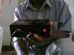
Figure 3. Code Recognition Device for Automobile
Testing
To test the device, an LED was provided to show the operations of the switching section of the device. The device was tested using the following numbering: when the numbers 1, 9, 7 and 4 were pressed from the pad, the relay would make contact, and at the same time the LED would come ON. When any other number, say 2, 3, 5, 6 or 8 was pressed, the LED would be OFF and the relay would lose contact. The output of the relay was projected out for easy interfacing with automobiles
The energising and de-energising of the relay shows that when the device is interfaced with the fuel pump of an automobile, the pumping of the fuel to the engine will be controlled accordingly and this will prevent the automobile from been stolen by an unauthorised person when parked.
Conclusion
There are available anti-theft security gadgets with associated drawbacks: either informs of costs, operations or securities break down. The Code Recognition Device for Automobile is cheap, simple in operation but sophisticated. No doubt cases of automobiles been stolen or snatched would be checked if devices like this are put to use.
References
2. Interpol, International Crime Statistics:
http://www.interpol.int/Public/statistics/ICS/default.asp, 2003.
3. Corelli, R. Deterring the Thieves, Macleans, 1998, 111 (33), p. 39.