Seasonal Sensible Thermal Energy Storage Solutions
Lavinia Gabriela SOCACIU*
Department of Mechanical Engineering, Technical University of Cluj-Napoca, Romania
E-mail: lavinia.socaciu@termo.utcluj.ro
* Corresponding author: Phone: +40744513609
Abstract
The thermal energy storage can be defined as the temporary storage of thermal energy at high or low temperatures. Thermal energy storage is an advances technology for storing thermal energy that can mitigate environmental impacts and facilitate more efficient and clean energy systems. Seasonal thermal energy storage has a longer thermal storage period, generally three or more months. This can contribute significantly to meeting society`s need for heating and cooling. The objectives of thermal energy storage systems are to store solar heat collected in summer for space heating in winter. This concept is not new; it is been used and developed for centuries because is playing an important role in energy conservation and contribute significantly to improving the energy efficiency and reducing the gas emissions to the atmosphere.
Keywords
Seasonal sensible thermal energy storage; Thermal energy storage; Heat storage; Underground Thermal Energy Storage (UTES); Aquifer; Hot-Water; Gravel-Water; Borehole.
Introduction
Societal energy demands are presently increasing while fossil fuel resources which dominate most national energy systems are limited and predicted to become scarcer and more expensive in coming years [1]. An important technology that can contribute to avoiding environmental problems and increasing the efficiency of energy consumption and that has widespread applications is thermal energy storage (TES).
TES is defined as the temporary holding of thermal energy in the form of hot or cold substances for later utilization, also is a significant technology in systems involving renewable energies as well as other energy resources as it can mare their operation more efficient, particularly by bridging the period between periods when energy is harvested and periods when it is needed.
TES is helpful for balancing between the supply and demand of energy. Thus, TES plays an important role in increasing the contribution of various types of renewable energy in the energy mix of regions and countries [1].
The main types of TES are sensible, latent and termochemical. Sensible TES systems store energy by changing the temperature of the storage medium, which can be water, rock, soil, etc. Latent TES systems store energy through phase change, e.g., cold storage water/ice and heat storage is melting paraffin waxes. Termochemical TES is more complex and more flexible than other thermal energy storage. Storage based on chemical reactions has much higher thermal capacity than sensible TES, but systems are not yet commercial viable and research and development is required to better understand and design these technologies and to solve other practical aspects before commercial implementation can occur.
The selection of a TES system for a particular application depends on many factors, including storage duration, economics, supply and utilization temperature requirements, storage capacity, heat losses and available space [1]. Sensible TES are simpler in design than latent heat or thermochemical storage systems, but suffer from the disadvantage of being bigger in size and cannot store or deliver energy at a constant temperature. Latent TES units are generally smaller than sensible storage units. More compact TES can be achieved based on storages that utilize chemical reactions.
Seasonal sensible thermal energy storage (SSTES) systems are designed to collect solar energy during the summer and retain the stored heat for use during the winter. The application requires large inexpensive storage volumes and the most promising technologies were found underground, using ground heat exchangers. Although such systems have been constructed and demonstrated, it is challenging to make them cost effective. Well designed systems can reduce initial and maintenance costs and improve energy efficiency. Economically justified projects can be designed using annual storage on a community-wide scale, which could reduce cost and improve reliability of solar heating [2, 3].
SSTES use energy stored or extracted by heating or cooling a liquid or a solid, through a heat transfer interaction and does not change its phase during this process. Energy storage materials for SSTES won`t experience phase change process when they store thermal energy. The only process those materials will experience is the change of temperatures within one phase. The amount of energy input to a SSTES is related to the mass of storage material and its heat capacity as well as the temperature difference of the storage medium between its initial and final states. The basic equation for heat transfer Q can be expressed as:
|
|
(1) |

where m denote the total mass of the storage material and cp the specific heat capacity of the storage material, T1 is the initial temperature of the storage material, T2 is the final temperature of the material and ΔT is the temperature difference before and after the storage operation. If the temperature range is too small to consider the variation of cp, equation (1) can be rewritten as:
|
|
(2) |
where cp.avg is the average specific heat capacity between temperature T1 and T2 [4,5].
The long term stability assures the low degradation of the heat storage material after thousands of thermal cycling. From the foregoing definition as well as equations (1) and (2), we can see that desirable SSTES requires the energy storage material to have four characteristics: high specific heat capacity, long term stability under the thermal cycling, good compatibility with its containment, low cost [6].
Generally speaking, there are four types of sensible seasonal thermal energy storage solutions: hot water thermal energy storage, aquifer thermal energy storage, gravel-water thermal energy storage and borehole thermal energy storage. Among these four storage solutions, hot-water thermal energy storage and aquifer thermal energy storage belong to the type of sensible water thermal storage; borehole thermal energy storage belongs to the type of sensible solid storage; while gravel-water thermal energy storage is a combination of sensible liquids and sensible solids storage. Figure 1 presents different types of seasonal sensible thermal energy storage solutions.
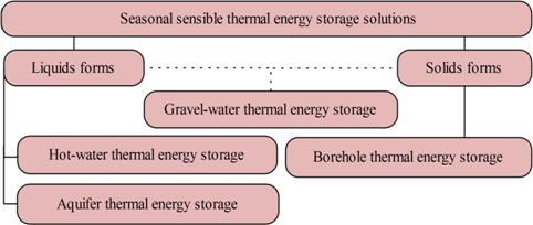
Figure 1. Different types of seasonal sensible thermal energy storage solutions
SSTES are simpler in design, but suffer from the disadvantage of being bigger in size and cannot store or deliver energy at a constant temperature. The cost of the SSTES solutions depends on the characteristics of the storage material. It is very common to utilize very cheap materials; e.g. for liquid: water or oils and e.g. solid: like rocks or sands as the storage medium [7].
Factors that limits the application of TES is that it is a cyclic, time-dependent energy source, and its effective utilization is dependent on the availability of efficient and effective energy storage systems. That is why energy storage is critically important to the success of any intermittent energy source in meeting demand. This problem is especially severe for solar energy because storage is needed the most when the solar availability is lowest, namely in winter.
Nowadays, with the reasonable cost and simple implementation, water storage technology is widely used in the solar thermal engineering field. Water has relatively high specific heat capacity, almost no degradation under thermal cycling, good compatibility with most of containment material, and most importantly, widely available and cheap. Water storage solutions have certain degrees of stratification, depending on the size, volume, geometries, water flow rates, and circulation conditions of the storage system. In the case of solids, the material is invariably in porous form and heat is stored or extracted by the flow of a gas or a liquid through the pores or voids [4,7].
The benefits of utilising TES systems can be divided in three groups: benefits for building owner (e.g. reduced heating/cooling costs, system`s components size and initial costs; improved indoor environmental quality), benefits for the environment and society (e.g. more viable utilisation of renewable energy resources; energy distribution with low line losses and high generation efficiency; eliminated the need for additional power plants; reduced source-energy consumption®fewer polluting emissions), and benefits for the energy provider (e.g. reduced peak electrical demand; increased efficiency of energy production; increased utility`s load factor) [8].
The aim of this research was to provide an overview of seasonal sensible thermal energy storage solutions.
Material and Method
The first step in realizing this bibliographical synthesis regarding “seasonal sensible thermal energy storage solutions” was the objective and rigorous selection of bibliographic references based on inclusion and exclusion clearly defined criteria. The bibliographic references that presented interest for the field of research study ware identified on Google website, as well as the database included.
References were searched in database query using the following phrases: “seasonal sensible thermal energy storage”. Because the number of results obtained was very high (i.e. 161000 results), I had additionally established following keywords: hot-water, gravel-water, borehole, aquifer, underground thermal energy storage (UTES). The query phrase used was: “seasonal sensible thermal energy storage solutions OR hot-water OR gravel-water OR borehole OR aquifer OR UTES OR underground thermal energy storage”. Application of these keywords restrict the field of search of bibliographic references, result a number of 88500 bibliographic references.
To ensure the objectivity and rigor in the selection procedure, I had defined a set of criteria for including bibliographical references presented in Table 1.
Table 1. Criteria for including bibliographical references
|
Field |
Criteria for including |
|
Language |
English |
|
File type |
Adobe acrobat PDF(.pdf) |
|
Periods |
2000-2011 |
Applying the selection algorithm described above, I had obtained a number of 13800 results. Then we excluded those references that were repeating; result a total of 468 bibliographic references, of which only 383 available. From the selection set of bibliographic references were excluded: brochures, conferences presentations, courses, posters, flyers, reports, patents and citations. Also, from the set of bibliographical references were excluded those that deal with issues presented in table 2.
Table 2. Exclusion criteria of bibliographical references
|
Exclusion criteria: |
|
|
Latent heat storage |
Central solar heating / cooling plants |
|
Phase change material (PCM) |
Combined heat and power (CHP) |
|
Thermochemical heat storage |
Heat pumps |
|
Electrical energy storage |
Zero energy consortium |
|
Ice storage |
Cooling storage system |
|
Air-conditioning systems |
Concentrating systems |
|
District energy |
Cogeneration |
In the next step I studied the abstracts as well as the contents for bibliographic references available, and then for each reference I decided if it is significant or not for the field of research.
I consider that this procedure of selection of bibliographical references is objective and rigorous. With this procedure I identified a set of bibliographical references likely to be a solid documentary basis for synthesizing the current state of research at national and international in the “seasonal sensible thermal energy storage solution” field.
During this rigorous research it came to my knowledge the fact that all the articles were referring to the “SSTES solutions” in the most elementary way. At this point I had made a supplementary research for each “SSTES solution (i.e. aquifer thermal energy storage (ATES), hot-water thermal energy storage (HWTES), borehole thermal energy storage (BTES) and gravel-water thermal energy storage (GWTES)” in order to develop the present paper and also to put together a much detailed source of documentation, if needed. Therefore this paper comprises a well-documented ground in the “seasonal sensible thermal energy storage solution” field.
Results and Discussion
Aquifer Thermal Energy Storage
In general, aquifer thermal energy storage (ATES) involves the free cooling from aquifers using the ground water as the carrier of thermal energy between the surface and the aquifer. The ground water has a constant temperature which is normally related to the mean annual air temperature at a specific location. In some cases, this temperature can be directly used for free natural cooling purposes. Such systems are regarded as passive in the sense that they are naturally recharged. However, in most cases, cold has to be actively stored in the aquifer to provide the temperature or cooling power that is demanded [9].
An ATES system (figure 2) consists of two wells (or two groups of wells) drilled into the aquifer and serve for extraction or injection of groundwater. For the usage as a heat store the hydraulic conductivity has to be high and no natural groundwater flow should be existent.
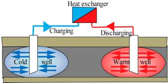
Figure 2. Aquifer thermal energy storage
During the heating season, water is extracted from the warm well, cooled and re-injected into the cold well. The circulation is reversed during the cooling season, so that cold water is extracted from the cold well, heated and re-injected into the warm well [9]. No heat insulation is possible for this kind of store. To keep heat losses in an acceptable range for high temperature application, the surface-volume-ratio has to be low. Because of the different flow directions both wells have to be equipped with pumps, production- and injection-pipes [10].
ATES can be distinguished in water saturated porous aquifers in sand, gravel or eskers and fractured aquifers in limestone, sandstone, igneous or metamorphic rock [10]. ATES which are filled with groundwater have high hydraulic conductivity. If there are impervious layers above and below and no or only low natural groundwater flow, they can be used for heat (and cold) storage [11].
In European climate conditions, the heat pump supported ATES for comfort cooling usually operates with a temperature of 5-8°C on the cold side and 12-18°C on the warm side. The systems are often designed to cover the total cooling demand of the building, while the heat production normally covers 50% of the load and some 70-80% of the energy. The seasonal performance factor of these systems ranges in most cases between 5 and 7 for the combined heating and cooling, while the cooling in itself often varies between a seasonal performance factor of 30 and 40. The investment is often paid back in less than 3-5 years and sometimes even faster [9].
ATES takes advantage of natural groundwater storage in the form of aquifers. There are two modes of operation, cyclic regime and continuous regime. The continuous regime is feasible only for plants where the load can be met with temperatures close to natural ground temperatures, and the storage part is more an enhanced recovery of natural ground temperatures. With a continuous flow, design and control of the system are much easier and simpler; only one well or group of well needs to be equipped with pumps. A disadvantage is the limited temperature range [12].
In a continuous flow regime (figure 3) water is continuously pumped from one well. Usually, in summer, hot water is injected through the other well, whilst in winter cold water is injected. Hence this type of system is very similar to a ground source heat pump and the temperatures within the storage aquifer will be close to ground temperatures.
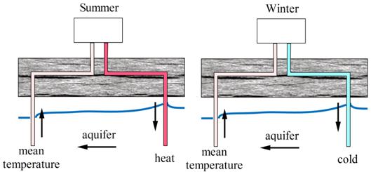
Figure 3. Continuous regime for aquifer thermal energy storage
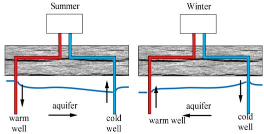
Figure 4. Cyclic regime for aquifer thermal energy storage
In a cyclic flow regime two wells (or sets of wells) are drilled into the aquifer (figure 4). During periods of heat recharge (very often in the summer) warm water is injected and a warm reservoir is developed. During periods of abstraction the heat reservoir is exploited from the other well (or wells). In such a cyclic system both sets of wells must be designed to produce or to accept groundwater [13].
Cyclic flow will create a definite cold and heat reservoir around each well or group of wells. It is possible to maintain a ground volume above or below the natural ground temperature all the time. One disadvantage is a more complicated well design and control system with each well being able to both produce and inject groundwater [12].
Some important parameters for an ATES installation are high ground porosity, medium to high hydraulic transmission rate around the boreholes, but a minimum of ground water flow through the reservoir. Ground water chemistry represents another set of parameters that must be given proper attention in order to prevent scale formation and furring [14].
Heat transport is both convective and conductive. The storage medium are ground water and the matrix (ground) containing the water. A common application is a double for cooling purposes [15]. Especially for high temperature heat storage a good knowledge of the mineralogy, geochemistry and microbiology in the underground is necessary to prevent damage to the system caused by well-clogging, scaling etc. [2,10]. With high temperature storage in aquifer, chemical problems have to mastered and controlled [15].
Hot-Water Thermal Energy Storage
The hot-water thermal energy storage (HWTES) has the widest range of utilization possibilities and can be built almost independently from geological conditions. Seasonal HWTES (figure 5) usually have a tank construction built of reinforced concrete, heat insulated at least in the roof area and on the vertical walls. It is usually built as steel or reinforced pre-stressed concrete tank, fully or partially buried in the ground [3].
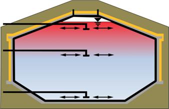
Figure 5. Hot-water thermal energy storage
The storage material used in HWTES is water, which gives good values concerning specific heat capacity and possible power-rates for charging and discharging, being the most favourable solutions from the thermodynamic point of view [3,10,11].
The first HWTES (Rottweil, Friedrichshafen and Hamburg) have been built with an additional inner stainless-steel liner to guarantee water tightness, to protect the heat insulation on the outside and to reduce heat losses caused by steam diffusion through the concrete wall. With the development of a new high density concrete material it was possible to built the store in Hannover without an inner steel-liner. Figure 6 and 7 shows cross-sections of the stores in Friedrichshafen and Hannover and the affiliated wall constructions [10].
The older stores have been built with only two levels for charging and discharging (on top and at the bottom). The Hannover store has a third device which is located below the upper third of the storage volume. This provides the following advantages during operation: it enables an optimized stratification in the store because low temperature heat can be charged into the store without disturbing higher temperature layers on top of the store. In addition simultaneous charging and discharging of the store at different temperature levels becomes possible. For the heat insulation a granulated foam glass has been used in Hannover, which is filled into textile bags at the side walls. The advantage of this material compared to the former used mineral wool is a faster and easier installation procedure and a better drying performance if it becomes wet. In Hannover, the insulation layer is protected by a steam barrier because the high density concrete is not absolutely tight against steam diffusion [10].
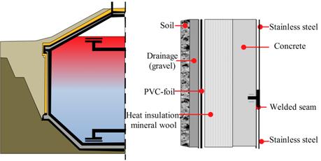
Figure 6. Construction of the water-tank stores in Friedrichshafen
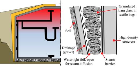
Figure 7. Construction of the water-tank stores in Hannover
Borehole Thermal Energy Storage
In borehole thermal energy storage (BTES), heat is stored directly into the ground. BTES do not have an exactly separated storage volume. The heat is transferred to the underground by means of conductive flow from a number of closely spaced boreholes [9].
There are two basic principles, open and closed, being used to transport the heat carrying medium in and out of the holes [14]. The two principles are illustrated in figure 8.
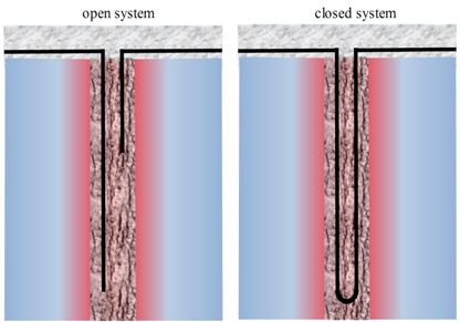
Figure 8. Basic principles for borehole thermal energy storage
In the open system is the inserting pipe placed with its outlet close to the bottom of the hole, whereas the extraction pipe has its inlet opening close to the top of the hole, but below the ground water table. The closed system uses u-pipes, and this means that the heat medium is pumped in a closed circuit, eliminating a number of potential problems with regard to water chemistry etc. that are inherent in the open system. The u-pipes act as a heat exchanger between the heat/cold carrying medium and the surrounding rock [14].
The boreholes can be equipped with different kinds of borehole heat exchangers (figure 9), making the boreholes act as a large heat exchanger between the system and the ground.
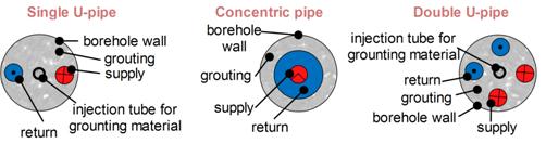
Figure 9. Different types of borehole heat exchangers
The most common borehole heat exchangers are a single U-tube made of plastic pipes (figure 10). However, sometimes more effective heat exchangers systems are used, e.g. double U-tube systems [9].
Heat is charged or discharged by vertical borehole heat exchangers which are installed into a depth of 30–200 m below ground surface. At charging, the flow direction is from the centre to the boundaries of the store to obtain high temperatures in the centre and lower ones at the boundaries of the store. At discharging the flow direction is reversed [11]. At the top of the store there is a heat insulation layer to reduce heat losses to the surface. Heat or cold is delivered or extracted from the underground by circulating a fluid in a closed loop through the boreholes. The fluid consists of water, which is mixed with glycol or alcohol to allow the system to work below the freezing point, if so required [9].
During periods of heat recharge warm water is pumped through the pipes and the rock mass heats up to produce a heat reservoir. During periods of heat abstraction cold water is pumped through the same boreholes to exploit the stored heat. Hence BTES systems work in a cyclic mode. The efficiency of the heat exchange will improve with higher thermal conductivities, but the rate of heat conduction away from the reservoir (hence heat loss) will increase with higher thermal conductivities. Therefore the important parameters for BTES are medium thermal conductivities, high specific heat and no groundwater flow [13].
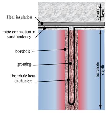
Figure 10. Borehole heat exchangers
BTES does not have vertical temperature stratification as the stores discussed above but a horizontal stratification from the centre to the borders. That is because the heat transfer is mainly driven by heat conduction and not by convection [10]. At the borders the temperature decreases because of the heat losses to the surroundings. The horizontal stratification is supported by connecting the supply pipes in the centre of the store and the return pipes at the borders [11].
One advantage of BTES is the possibility for a modular design. Additional boreholes can be connected easily and the store can grow with e.g. the size of a housing district [11]. A certain number of heat exchangers are hydraulically connected in series to a row and certain rows are connected in parallel, or in a combination serial/parallel depending on the planned thermal loading and unloading of the facility. The shape of the storage facility, seen at the surface, can be adapted to the shape of the available land area as illustrated in figure 11 [14].
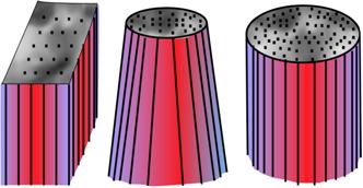
Figure 11. Different patterns used in borehole thermal energy storage
An important issue in the design of underground seasonal storage systems using borehole heat exchangers is to find cost-effective methods to construct the borehole thermal energy storage field so that heat can be injected or extracted from the ground without excessive temperature differences between the heat carrier fluid and the surrounding ground. As a result of the limited thermal conductivity the heat losses are rather moderate and storage efficiencies of 70% can be reached. In contrast good thermal contact between the heat exchangers and the ground is required to allow a good heat transfer rate per unit area of the heat exchanger tube [10].
The heat transfer between the heat carrier fluid and the surrounding ground depends on the arrangement of the flow channels, the convective heat transfer in the BTES, and the thermal properties of the materials involved in the thermal process. The two major thermal resistances associated with these different parts are the thermal resistance between the heat carrier fluid and the borehole wall, borehole thermal resistance, and the thermal resistance of the surrounding ground from the borehole wall to the some suitable average temperature level, often chosen to be the local average ground temperature [3].
The most important parameters influencing the borehole thermal resistance are the thermal conductivity of filling material, the number of pipes, pipe position and the pipe thermal conductivity [10]. Some important parameters for a successful BTES are: rock with high specific heat, medium to high thermal conductivity, and compact rock mass with (virtually) no ground water flow. Other important parameters are the type of rock including grain size and the types of minerals [14]. Suitable geological formations for this kind of heat storage are e.g. rock or water-saturated soils.
The advantages of BTES are the extend ability and the lower effort for construction compared to HWTES and GWTES. This also leads to lower costs. On the other hand the size of a BTES has to be three to five times higher compared to a HWTES for the storage of the same amount of heat. This is because of the reduced heat capacity of the storage material and the smaller power rates for charging and discharging due to the heat transfer in the borehole thermal energy storages. Often an additional buffer store is necessary as well [10,11].
Seasonal storage in the ground, using ground heat exchangers, seems to be favourable from technical and economical point of view. Depending on the temperature level, the thermal energy is extracted either by a heat pump (low temperature ground storage < 40°C) or directly (high temperature ground storage, 40-80°C) and delivered to the customers. The thermal performance of such systems is influenced by the heat and moisture movement in the area surrounding the heat exchangers [3].
The performance factor of heat pump supported BTES systems will normally be in the range 4-5, depending on the amount of cold produced in the system. The cold production (free cooling) in itself is normally around 20-30. The pay-back time for these kinds of systems ranges between 5 and 10 years; depending on size and other circumstances. This is significantly higher than for ATES, but on the other hand, the operational risks are much lower [9].
Gravel-Water Thermal Energy Storage
Gravel-water thermal energy storage (GWTES) is normally buried in the ground, but close to the surface in order to reduce excavation costs. GWTES need to be insulated both on the top and along the inclined walls. The top is usually covered with a load carrying construction, so that the surface area can be used for some purpose or other. Depending on the size and shape bottom insulation can be advisable as well. In figure 12 is presented a GWTES system.
The storage material usually is a mixture of gravel and water, also sand/water or soil/water mixtures are possible [10,11]. The storage temperature can be up to a maximum of 95oC, provided that the liner is made of either advanced polymer materials or metal [14]. Heat is charged into and discharged out of the store either by direct water exchange or by plastic pipes installed in different layers inside the store [11]. Stratification should be supported by the charging devices. No load-bearing frame structure is required because forces are taken down to the side walls and to the bottom by the gravel. The principal heat transport process in the storage is convective [15]. Because of the reduced specific heat capacity, the volume of the store has to be approximately 50% bigger compared to a HWTES to store the same amount of heat at the same temperature levels [10,11].
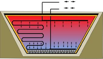
Figure 12. Gravel-water thermal energy storage
In figure 13 is presented the wall construction of the currently newest store in Steinfurt, which consists of a protection fleece at the inside, a double poly-propylene (PP) lining with a vacuum control system to identify leakages during installation and operation, a steam barrier, heat insulation (granulated foam glass) and a drainage system [10].
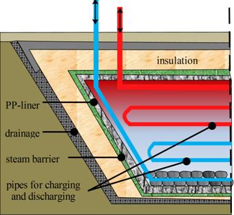
Figure 13. Construction of the gravel-water thermal energy storage in Steinfurt
Summary
A summary of geological requirements for seasonal thermal energy storage solutions is shown in table 3.
Table 3. Geological requirements for seasonal thermal energy storage solutions
|
Storage concept |
Geological requirements |
|
Hot-water |
-stable ground conditions, -preferably no ground water, -5-15m deep. |
|
Aquifer |
-natural aquifer layer, high hydraulic conductivity, -confining layers on top and below, -no or low natural ground water flow, -suitable water chemistry at high temperatures, -20-50m thickness. |
|
Gravel-water |
-stable ground conditions, -preferably no ground water, -5-15m deep. |
|
Borehole |
-drillable ground, -ground water favorable, -high heat capacity, -high thermal conductivity, -low hydraulic conductivity, -natural ground water flow less than 1 m/a, -30-200m deep. |
The main problem with water storage systems is the corrosion for long operation periods. Another disadvantage of water storage systems is that volume of the storage may be very large for large heat capacities and therefore the whole system becomes very heavy. With rock storage there is no corrosion or scale forming problem but volume of the system might increase with an increase in cost. Rock storage systems have larger amortization periods because they have no corrosion and deformation problems, but with their volumes being large, their total initial costs are very high.
Conclusions
The principle methods available for seasonal storage of solar thermal energy mostly store energy in the form of sensible heat. Long-term storage systems prove being more effective in reducing fossil fuels use and complying with CO2 emission policies.
All the sensible heat storage concepts have one basic challenge in common. When heat or cold is charged into or discharged from the store, there will be temperature differences in different parts of the storage volume. Storage of sensible heat results in energy losses during the storage time, storage temperature, storage volume, storage geometry, and thermal properties of the storage medium.
In most countries the usage of the ground for thermal energy storage has to be approved by the local water authorities to make sure that no interests regarding drinking water are affected. The decision to use a certain type mainly depends on the local conditions, on the geological and hydro-geological situation in the ground below the respective construction site. A good knowledge of the mineralogy, geochemistry and microbiology in the underground is necessary to prevent damage to the system caused by well-clogging, scaling etc.
References
1. Abedin A.H., Rosen M.A., A Critical Review of Thermochemical Energy Storage Systems, The Open Renewable Energy Journal, 2011, 4, 42-46.
2. Pavlov G.K., Olesen B.W., Seasonal ground solar thermal energy storage – review of systems and applications, Proceedings of ISES Solar World Congress, Kassel (DE), 28.08-02.09.2011.
3. Pavlov G.K., Olesen B.W., Seasonal solar thermal energy storage through ground heat exchangers – review of systems and applications, Proceedings of 6th Dubrovnik Conference on Sustainable development of Energy, Water and Environmental Systems, Dubrovnik, Croatia, 25-29.09.2011.
4. Sunliang C., State of the art thermal energy storage solutions for high performance buildings, Master`s thesis, University of Jyvaskyla, Finland, 2010.
5. Incropera F.P., Dewit, D.P., Fundamentals of heat and mass transfer, 5th ed., John Wiley and Sons, 2002.
6. Hasnain S.M., Review on sustainable thermal energy storage technologies, part I: Heat storage materials and techniques, Energy Conversion and Management, 1998, 39, p. 1127-1138.
7. Ercan Ataer O., Storage of thermal energy, in Energy Storage Systems, in Encyclopedia of Life Support Systems (EOLSS), Developed under the auspices of the UNESCO, Eolss Publishers, Oxford, UK 2006, http://www.eolss.net, (accessed 08/11/2011).
8. Pavlov G., Olesen B.W., Building thermal energy storage –concepts and applications. Available at: http://www-ttp.particle.uni-karlsruhe.de/GK/Workshop/blobel_maxlik.pdf (accessed 10/07/2009).
9. EU Commission SAVE Programe & Nordic Energy Research, Soil Cool /Rekyl project – Pre-design guide: For ground source cooling systems with thermal energy storage, Edited by COWI. Available at: http://www.cowiprojects.com/soilcool/pdf/Pre-guide-final.PDF, 2004, (accessed 08/11/2011).
10. Schmidt T., Mangold D., Muller-Steinhagen H., Seasonal thermal energy storage in Germany, ISES Solar World Congres, Goteborg, Schweden, 14-19.06. 2003.
11. Schmidt T., Mangold D., Muller-Steinhagen H., Central solar heating plants with seasonal storage in Germany, Solar Energy 2004, 76, 165-174.
12. Kun S.L., A Review on Concepts, Applications, and Models of Aquifer Thermal Energy Storage Systems, Energies 2010, 3, 1320-1334; doi:10.3390/en3061320.
13. Evans D.J., Reay D.M., Mitchell W.I., Busby J., Appraisal of underground energy storage potential in Northern Ireland, Keyworth, Nottingham British Geological Survey, 2006.
14. Nielsen K., Thermal energy storage: A state-of-art, a report within the research program Smart Energy-Efficient Buildings at NTNU and SINTEF 2002-2006, 2003.
15. Pahud D., Geothermal-energy, Available at: http://www.internet-public-library.org/carbon-reduction/ground-heat-storage.pdf, (accessed 08/11/2011).