A novel Control Algorithm Expressions Set for not Negligible Resistive Parameters PM Brushless AC Motors
Renato RIZZO1*, Andrea DEL PIZZO1, and Ivan SPINA1
1 Department of Electrical Engineering - University of Naples Federico II
Via Claudio 21, Naples, Italy
E-mails: renato.rizzo@unina.it; andrea.delpizzo@unina.it; ivanspina@gmail.com
* Corresponding author: Phone: +39 081 7683231
Abstract
This paper deals with Permanent Magnet Brushless Motors. In particular is proposed a new set of control algorithm expressions that is realized taking into account resistive parameters of the motor, differently from simplified models of this type of motors where these parameters are usually neglected. The control is set up and an analysis of the performance is reported in the paper, where the validation of the new expressions is done with reference to a motor prototype particularly compact because is foreseen for application on tram propulsion drives. The results are evidenced in the last part of the paper.
Keywords
Permanent magnets; Brushless motor.
Introduction
Permanent Magnet brushless motor drives (PMSM) are widely demanded in many and various application such as generation by renewable sources like wind [1,2], and especially in industrial and traction applications [3-6], thanks to their compactness and good dynamic features. As all motors utilized in electric drives or any other complex system, nowadays also smart energy distribution systems [7-9], it is necessary to feed them by power electronic converter and set up proper control of the whole drive according to the specific requested operation and performance [10-13].
In order to improve their performance, reliability and availability, many control algorithms have been proposed in literature, starting from the value of the electrical parameters in the Park’s reference system.
These algorithms are mainly based on the hypothesis to neglect motor resistive parameters. This hypothesis is not acceptable in case of very compact motors, i.e. light traction motors, in these cases is preferred to have a lower efficiency and dissipate the loss energy adopting a more efficient liquid cooling system. Such simplified control algorithms can introduce unacceptable errors that can produce damages to the machine or reduce their lifetime [14].
The influence of resistive drops on machines voltage depends in particular on the load and speed. A quick method to evaluate the negligibility of resistances could be the evaluation of the influence of resistive drop on the rated voltage. Acceptable values are 1-2%, for higher values is better to redefine the operative limits and control trajectories.
In the paper is proposed a control algorithm which is realized taking into account the resistive parameters of the motor, the control is validated by a numerical analysis with reference to a motor prototype for tram propulsion application.
Preliminary Definition and Traditional PMSM Expressions
In order to see how the several PMSM mathematical expression get modified ones the resistive parameters are introduced, it is convenient to recall them. The rotor reference system mathematical model is reported in (1) together with the torque expression.
|
|
(1) |

The traditional control of the motor is based on the model (1) and the reference current components isd*, isq* must ensure the satisfaction of the two main limits of operation (2) and (3) regarding respectively the maximum current (Is,L) and the maximum voltage (VL)
|
|
(2) |
|
|
(3) |
in particular (3) is written from the first of (1) in steady-state operation, separating the d,q components and using the approximation of negligible resistive parameters. In Park’s reference system the (3) represents the equation of a circle centered in (-Φr/Ls,0) and with radius (VL/pωrLs). In fig.1-a the (2) is depicted together with (3) for three specific value of speed called ‘characteristic speeds’ of the motor.
Figure 1. a) Characteristic PMSM speeds for simplified expressions b)Main current limits for simplified expression
The expression of the characteristic speeds ωr,B, ωr,0 and ωr,L is:
|
|
(4) |

The maximum iq current component is indicated with iq,max and is:
|
|
(5) |

with:
|
|
(6) |

if is known the desired torque Te* at the fixed speed ωr, the reference current component isd*, isq* are expressed by:
|
|
(7) |

with:
|
|
(8) |
|
|
(9) |


A geometrical representation of iq0l, idf is reported in fig.1-b.
Limit Expressions Modified by Resistive Parameters Introduction
Since the resistive parameters are not always negligible, they should be taken into account when defining the control algorithm trajectories. In particular the approximation used in the maximum voltage (3) has to be removed and a complete expression has to be considered:
|
|
(10) |
in comparison with (3), (10) still represents the equation of a circle, but with different center and radius, the radius RVL and the coordinates of the center cd, cq are:
|
|
(11) |
|
|
(12) |


The sign of inequality in (10) represents the inner area of the circle. If Rs=0, as it can be noticed, relations (10-12) yield the expressions traditionally used to define the voltage boundary of a PMSM. Since the resistance is a physical parameter, it cannot be equal to zero, this leads to the following considerations:
1. At null speed, the maximum current which satisfies the voltage limit is not infinitive, but equal to VL/Rs (the order of magnitude of this value is quite high, typical of short circuit current values);
2. At fixed speed, the value of current for not overcoming the voltage limit becomes equal to (11), which can be seen as the ratio between the voltage VL and an impedance with Rs as real part and pwrLs as imaginary part;
3. The coordinates cd, cq are speed dependent.
From the (12) it is possible to write:
|
|
(13) |
where pwr can be calculated from the second of (12):
|
|
(14) |

To obtain the final relation between the coordinates cd and cq, (14) is substituted into (13), this yields:
|
|
(15) |

then it is possible to understand how the center of the circle (10) moves when speed increases. In fact, (15) is another equation of a circle centered in the point (−Fr/2Ls) and with radius Fr/2L. When speed is zero, cd = cq =0, and the center of the circle (10) is situated in the origin of axis; with the approximation (3) this center was always placed in (−Fr/2Ls, 0), independently from the speed. By increasing the speed, cd and cq become different from zero and both negative, if wr is assumed positive (for positive wr eq.15 describes a semi-circle). Thus, with the increase of the speed the center of the circle moves on the semi-circle (15), as depicted in fig.2.
In fig.2 is represented (15) with the semi-circle in dashed line, the arrow (clockwise) is coherent with the positive increasing of wr, the point (−Fr/2Ls,0) has been reported for wr→∞; only for wr→∞ the center of the approximated expression (3) coincides with the one of (10). The circle in continuous line indicates the maximum current Is,L.
If the motor parameters are known, for any value of wr the coordinates cd, cq are univocally defined, together with the radius RVL, this allows to individuate the working area on the d,q domain; an example is given in Fig.3.
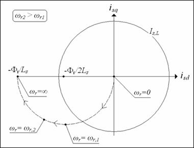
Figure 2. Voltage limit centre displacement on Park’s reference system and current limit
Figure 3. Working area on Park’s reference system when using complete expressions
The working area is colored in grey in fig.3 for a fixed value of the speed wr*. On the same figure it is also possible to see how the working area gets enlarged or contracted for respectively higher and lower value of speed.
With respect to the approximated expression (3), (10) yields a reduced working area on the first quadrant of d,q domain. This happens because the circle (10) has a shorter radius and its center is moved in the negative direction of q-axis.
Same considerations can be done also with reference to the PMSM mathematical model (1): the addition of the resistive voltage drop (Rs Is) makes the voltage Vs reaching its own limit for lower values of current Is, at fixed speed wr, and/or for lower value of wr, fixing the current Is.
The modification of the working area in d,q axis reference is reflected on the Te −wr domain as well, changing the definition of characteristic speeds and the values of maximum d,q current components which satisfy the limit of the voltage. This influences also the control algorithm, modifying the reference trajectories.
New Control Reference Trajectories
All the characteristic speeds above defined, considering the new maximum voltage expression (10), have to be re-calculated. Also their representation on d,q domain appears different than the one of fig.1, and it is proposed in fig.4.
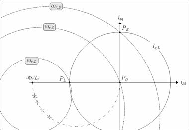
Figure 4. Characteristic PMSM speeds when using complete expressions
The characteristic speed wr,B has been calculated starting from the maximum voltage expression (3) and imposing id=0, iq=Is,L. The base speed wr,B has now to be re-defined as:
|
|
((16) |

Applying the same procedure, the limit speed changes in:
|
|
(17) |

Differently from wr,B and wr,L the characteristic speed wr,0 does not change with the introduction of resistive parameters, because it is calculated imposing zero id, iq current components in the maximum voltage expression; wr,0 remains defined by (4).
By adding the resistive parameters in the maximum voltage expression, also the maximum current changes, in particular the component iq0l, iqfl, have to be re-calculated, while their composition remain the one of (8) and (5) in the different ranges of speed. For sake of simplicity the following positions are adopted:
|
|
(18) |
In fig.5 (10) and (2) are depicted in d,q domain for a fixed value or wr >wr,B, and iq0l is the ordinate of the point A.
Figure 5. Q-axis current limit for applying ‘max(T/I) strategy’ when using complete expressions
By applying Pythagoras theorem, iq0l is calculated:
|
|
(19) |
The same can be done for the quantity iqfl (ordinate of point A in fig.6).
From fig.6 it is simple to verify that:
|
|
(20) |

Which gives the iqfl expression:
|
|
(21) |

Figure 6. Q-axis current limit when using complete expressions
In flux weakening region, the d-axis current component idf expressed by (9) has now to be re-defined. In fig.7 the reference current component isq* is supposed to be known and the speed wr assigned higher than wr,B. The component idf is necessary to assure that the voltage keep within the maximum value VL.
The current idf can be easily calculated by means of geometrical consideration and is:
|
|
(22) |
Ones assigned the reference torque Te* at fixed speed wr, the reference current components is formally defined, but the quantities wr,B, wr,L, iq0l, iqfl, idf have to be calculated respectively as in (16), (17), (19), (21) and (22); while wr,0 remains defined by (4).
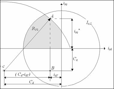
Figure 7. Flux weakening d-current when using complete expressions
Numerical Analysis
A numerical analysis is carried out with reference to a traction advanced prototype motor whose parameters are reported in table1.
Table 1. PMSM motor parameters
|
Rated values |
||
|
Power |
Pn |
67.5 kW |
|
Electromagnetic torque |
Te,n |
2014 Nm |
|
Speed |
ωr,n |
33.51 rad/sec |
|
Current (rms) |
Is,n |
120 A |
|
Phase voltage (rms) |
Vf,n |
286 V |
|
Limit values |
||
|
Electromagnetic torque |
Te,L |
2910 Nm |
|
Current (maximum) |
Is,L |
170 A |
|
Phase voltage (maximum) |
VL |
286 V |
|
|
||
|
Stator phase resistance |
Rs |
332 mΩ |
|
Stator self inductance |
Ls |
5.40 mH |
|
Permanent magnets flux-linkage |
Фr |
0.998 Wb |
This water-cooled motor is intended to replace the actual induction motors on tram application and, in order to eliminate the speed reducer and lowering the floor, it has been designed with the specification of high compactness [15]. This makes the resistance a not negligible parameter and the resistive voltage at rated current turns to be about 14% of Vf,n.
With reference to the motor of tab.1, in fig.8-a the working area on the Te - wr domain is delimited by two different curves. The outer curve refers to iq,max with iqfl calculated as in (6) based on the approximation (3). The inner curve, instead, refers to the complete expression (21) of iqfl.
Figure 8. Te-ωr domain for approximated and complete expression:
a)when using ‘flux weakening strategy’ b) when using ‘maximum torque/current strategy’
The portion of the domain where the ‘maximum torque/current strategy’ is possible is represented in fig.8-b; as before the outer curve refers to the approximated iq0l (9), while the inner curve refers to the complete expression (19) of iq0l. As it can be noticed, the resistive parameters contract the working area in order to ensure that the voltage keeps within its limit. If vice versa the control algorithm was not based on the complete expression of the limits, it would force the motor to work on the darker portion of fig.8 overcoming the limit voltage. On the other hand, the simplified expressions are easier to be implemented and require a lower computational burden from the control system. A different solution to ensure the voltage within proper limits is using the approximated expression but choosing a value for VL lower than the rated voltage VR. In fig.9 the working area – divided in the part of ‘maximum torque/current strategy’ and ‘flux weakening strategy’’ – is reported for two different set of equations: the red line refers to the complete expression and with VL equal to VR; the black line refers to the approximated expression with VL nearly equal to 94% of VR.
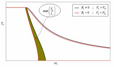
Figure 9. Te-ωr domain for complete expression with the right value of VL and for approximated expression with a lower value of VL
The use of approximated expression with lower VL drags the outer line of the calculated domain within the real limit, but produces a restriction of the ‘maximum torque/current strategy’ domain, as it can be seen in fig.9. This reduces the motor performances and increase the loss of power.
Conclusions
A novel control algorithm expressions set for not negligible resistive parameters PM Brushless AC motors has been proposed in the paper. This algorithm is based on a new set of control algorithm expressions that is realized taking into account resistive parameters of the motor, differently from simplified models of this type of motors where these parameters are usually neglected. The control has been presented and explained including a critical analysis of the performance, the validation of the new expressions is done with reference to a motor prototype particularly compact because is foreseen for application on tram propulsion drives. The results complete the paper evidencing the effectiveness of the novel algorithm proposed for light trains application.
References
1. Piegari L., Rizzo R., Tricoli P., High Efficiency Wind Generators with Variable Speed Dual-Excited Synchronous Machines, Proceedings of International Conference on Clean Electrical Power ICCEP 2007, Capri (Italy), 2007, pp. 795-800.
2. Pillay P., Krishnan R., Modelling, Simulation, and Analysis of Permanent-Magnet Motor Drives, Part I: The Permanent-Magnet Synchronous Motor Drive, IEEE Transactions on Industry Applications, 1989, 25(2), p. 265-273.
3.
Benchaib A., Alacoque J.C.,
Poullain S., Thomas J.L., Discrete-time field-oriented control for SM-P
4.
Belin S., Scrooby
M., Masselus J., Jobard T.,
Courtine S., A P
5.
Bae B.H., Sul
S.K., Kwon J.H., Shin J.S., Implementation of sensorless
vector control for super high speed P
6. Ahmadi D., Nasiri A., A Novel Digital Control Method of PMSM for Automotive Applications, Proc. Vehicle Power and Propulsion Conference VPPC, 2007, p. 180-184.
7. Brando G., Dannier A., Del Pizzo A., Rizzo R., A High Performance Control Technique of Power Electronic Transformers in Medium Voltage Grid-Connected PV Plants, Proc. of International Conference on Electrical Machines ICEM 2010, Roma (Italy), Sept., 2010, p. 1-6.
8. Brando G., Dannier A., Rizzo R., Power Electronic Transformer application to Grid-connected Photovoltaic Systems, Proceedings of International Conference on Clean Electrical Power 2009, Capri (Italy), June, 2009, pp. 685-690.
9. Andreotti A., Del Pizzo A., Rizzo R., Tricoli P., An efficient architecture of a PV plant for ancillary service supplying, Proceedings of International Symposium on Power Electronics Electrical Drives Automation and Motion (SPEEDAM 2010), 2010, Pisa (Italy), June, 2010, pp. 678-682.
10. Simanek J., Novak J., Dolecek R., Cerny O., Control Algorithms for Permanent Magnet Synchronous Traction Motor,. Proc. International Conference EUROCON 2007; Sept., 2007, pp. 1839-1844.
11. Aguirre M., Calleja C., Lopez-de-Heredia A., Poza J., Aranburu A., Nieva T., FOC and DTC comparison in PMSM for railway traction application, Proceedings of 14th European Power Electronics and Applications (EPE 2011), 2011, pp. 1-10.
12.
Brando G., Dannier
A., Del Pizzo A., Rizzo R., Quick
identification technique of fault conditions in cascaded H-Bridge multilevel
converters, Procedings of International Aegean
Conference on Electrical Machines and Power Electronics ACEMP 2007, Bodrum (
13. Rizzo R., Tricoli P., Power Flow Control Strategy for Electric Vehicles with Renewable Energy Sources, Proceedings of Power and Energy Conference PECon 2006, Malaysia, Nov., 2006, pp. 34-39.
14. Fodorean D., N'diaye A., Bouquain D., Miraoui A., Characterization and control of a permanent magnet synchronous motor used in vehicle application, International Conference on Automation Quality and Testing Robotics (AQTR), 2010, 3, p.1-6.
15. Peroutka Z., Zeman K., Krus F., Kosta F., Control of permanent magnet synchronous machine wheel drive for low-floor tram, Proceedings of 13th European Conference on Power Electronics and Applications (EPE), 2009, 1-9.