Design and Fabrication of an Industrial Poultry Feed Tumble Mixer
Osokam Shadrach ONYEGU*, Ogbanga IBIFURO, Monday Nsikan IDUNG,
and Thompson AGUHEVA
Department of Mechanical Engineering, Faculty of Engineering, University of Port Harcourt,Port Harcourt, Nigeria
E-mails: shadrackxx@yahoo.com, ogbanga123@yahoo.com, polymath@yahoo.com,
profosom@yahoo.com
* Corresponding author: Phone: +2348064063426
Abstract
This paper presents the design and fabrication of a poultry feed industrial tumble mixer. The design computations to handle a 50Kg mass of feed was done in the MS Excel environment for proper machine design approach. The machine was designed using AUTOCAD 2D/3D design software and proper material selection was done before the assembling and fabrication of parts. The efficiency of the machine, its associated cost of production and the product obtained after few minutes of mixing were outstanding, thereby, making the design acceptable and cost effective.
Keywords
Shaft design; Blade design; Computer-aided design; Parametric design; Mixer.
Introduction
The use of hand to mix the crushed poultry feed by the traditional agricultural sector characterized by subsistence farming was perhaps the first form of poultry feed mixer. This method was subsequently developed by the use of manually operated machine after the advent of industrial revolution in Great Britain.
There is a universal demand for poultry feed due to its use in domestic poultry as a machinery for food production. Our small-scale industries in the country are in dire need of a highly nutritious poultry feed for their birds to increase production output. The necessity to boost and sustain the economy which require a well planned industrialization to suit local conditions and demand could accelerate the pace and scope of industrialization by increasing the level of our designing and manufacturing (computer-aided) rather than mere assembling activities such an effort would reduce importation of machines, spare parts and components that can be produced locally [1-4].
Since the bulk of the economic activity in the rural parts of the country is agriculture, it is general knowledge that those who are engaged in agriculture are the poor in comparison with those who engaged in other sectors of the economy in Nigeria that is to say their standard of living is so low that shortage of funds to enable them purchase modern facilities has been a major handicap in the development of agriculture.
Most of the poultry farmers still employ crude techniques for processing their products. For example, they still use hands to mix already crushed poultry feeds. These crude techniques are not only labor intensive but also lead to low level production of small quantities of poultry feeds. Investigation shows that the few available small scale processing equipment are not very efficient. This lack of efficient small scale processing equipment to the farmers has increased the inability of their farming activities.
The principle of operation is a very simple one. Already crushed poultry feed ingredients are placed between stationary drum and the rotating inclined blades agitates the feeds which mixes the various poultry feed ingredients as a result forces between the poultry feeds and the stationary drum on one hand and the frictional forces between neighboring feeds. The making of poultry feeds which has hitherto been regarded as an exclusive function of the poultry farmer can be done by anybody who will need a little training on the operation of the machine, in addition time and space is a major advantage as not only that the long duration normally involved has been reduced but the numerous containers ranging from mortar, pestle, basin etc, have been limited to the machine.
The major constraint is that of the source of power. The machine has an electric motor which utilizes electricity, the cheapest source of power so far. The motor selection has been done with consideration given to the torque speed and hence the power requirement [5]. For a rapid or sustainable economic development in Nigeria and Africa at large, a developed agricultural sector is necessary. A means of alleviating this problem is the provision of modern facilities made locally at cheaper rates. This will lead to increased productivity in agriculture which could enable manufacturer and consumers to benefit from the supply of relatively cheaper and better produce at the right time and in sufficient quantity. For these demands to be met to maintain a sustainable economic growth in Nigeria, a much higher production level in the agricultural sector is necessary through the use of locally designed and fabricated equipment based on its efficiency, durability, less capital intensive, strength and rigidity [6].
Unprofessional admixing of liquid components in the main mixer can causes insufficient homogeneity by formation of agglomerates and deposits on the mixing tools and walls. These deposits as sticks and crusts cause carry-over and cross contamination stochastically which cannot be compensated by rinsing batches. Mainly in cases of the mixing process by ribbon mixer, solid dispersed components have a better suitability than liquids [7]. The Microsoft (MS) Excel offers a suitable environment for the development of design computations [8,9]. Oko and Diemuodeke [10] developed a spread sheet add-in for psychrometric data analysis to be used by engineering students and researchers. In their work, they showed the importance associated with using Microsoft (MS) Excel as a critical tool in carrying out design analysis.
The objective of this paper was, therefore, to design and fabricate a multi-purpose industrial tumble drum mixer at a cheaper and more affordable prices to our farmers, this work aims at producing feeds for poultry birds. It seeks to develop a model that will use electrically operated industrial poultry feed tumble mixer which arises from the fact that most of the locally produced feeds has undergone primitive and inefficient means of manual processing. This machine will be designed and fabricated with a view to reducing the dependency of manual operation and making convenience by reducing human effort and time by exploring the various principles associated with machine design.
Material and Method
Design Analysis
The automated industrial poultry feed tumble mixer is made up of the following major parts; Electric Motor, Metal Bucket/ the mixing trough, Shaft Pulley, Motor Pulley, Set of blades mounted on the shaft, Bearings, Shaft, Supporting Structures, V-Belt etc. The poultry feed mixer can achieve the desired poultry feed mixing based on the following design specification of the various components of the machine.
· The shaft is designed to rotate at a relative speed of 800rpm and this is achieved by proper pulley selection to reduce the speed of the electric motor that has a speed of 1500rpm.
· The design will provide for ease of operation and maintenance as well as the safety of the operator.
Design of Mixing Trough
The mixing trough is a combination of rectangular top and a cylindrical base. The trough is made of mild steel with density of 7850kg/m3 at room temperature with thickness of 0.12cm [5].
Volume of rectangular box:
|
Vr=LHW |
(1) |
where Vr [mm3], L = length in [mm], H = height in [mm], W = width [mm].
Volume of half cylinder:
|
Vc=1/2(πr2L) |
(2) |
where Vc [mm3], r = radius in [mm].
Total volume of the mixing trough, V[mm3]:
|
V=Vr+Vc |
(3) |
Surface area of the rectangular box, Ar [mm3]:
|
Ar=2H(L+W) |
(4) |
Surface area of half cylinder, Ac [mm2]:
|
Ac=πHL |
(5) |
Total surface area of the mixing trough, At [mm2]:
|
At=Ac+Ar |
(6) |
Volume of material, Vm [mm3]:
|
Vm=0.2×At |
(7) |
Mass of mixing trough, M [Kg]:
|
M=Vmxρ |
(8) |
where ρ[kg/m3] is the density of the design material.
Weight of empty trough, W [N]:
|
W=Mxg |
(9) |
where g [m/s2] is acceleration due to gravity.
Weight of trough with feeds ingredient, Wt [N]:
|
Wt=W+Wf |
(10) |
where Wf[N] is the weight of poultry feed ingredients.
Design of Shaft and Blade
Tangential load:
|
Wtx=2Tx/Dx |
(11) |
|
Wty=2Ty/Dy |
(12) |
|
Wtz=2Tz/Dz |
(13) |
where Ti [Nmm] is the torque on the blade and the subscript “i” represents blades x, y and z.
Normal load exerted:
|
Wnx=Wtx/cosθ |
(14) |
|
Wny=Wty/cosθ |
(15) |
|
Wnz=Wtz/cosθ |
(16) |
Normal load acting vertically:
|
Wnvx=Wnxcosθ |
(17) |
|
Wnvy=Wnycosθ |
(18) |
|
Wnvz=Wnzcosθ |
(19) |
Normal load acting horizontally:
|
Wnhx=Wnxsinθ |
(20) |
|
Wnhy=Wnysinθ |
(21) |
|
Wnhz=Wnzsinθ |
(22) |
The shaft is a rotating member of circular cross-section which transmits power from one point to another. The following assumptions were made; the shaft is designed for combined torsion and bending that is, it is subjected to bending moment and torsion [12].
Selection of the Pulleys and Determination of Their Speeds
The relationship below is used to determine the transmitted speed:
|
|
(23) |
where N1 [rpm] and N2[rpm] are the speeds of driver and driven pulley; D1[mm] and D2[mm] are the diameters of driver and driven pulley. The intended ratio of the speed of the driven pulley to that of the driver pulley used in the design is 4:5.
The center distance, C [mm], between two adjacent pulleys is determined using the relation [6]:
|
|
(24) |
The length of the open belt, L [mm], is given as:
|
|
(25) |
In engineering, flexible drives such as ropes and belts can be used for power transmission over comparatively long distance instead of more expensive transmission drives such as gears.
Torsion on the Shaft, To [N], exerted by the electric motor is computed using the equation below:
|
|
(26) |
where P [W] is the power rating of the electric motor = 2hp.
The net force, FN[N], exerted by the belt on the shaft is determined as follows:
|
FN=F1-F2 |
(27) |
Torque acting on the pulley, T is:
|
T=FNxD2/2 |
(28) |
|
T/R2=F1-F2 |
(29) |
Where F1 [N] and F2 [N] are the tensions on the tight side and slack side; R2 [mm] is radius of driven pulley.
|
F1/F2=eμθ |
(30) |
Where θ= angle of contact in [rad]. For open belt:
|
|
(31) |
|
|
(32) |
From standard table the coefficient of friction for
belt/pulley material that is tanned leather/iron steel is ![]() [6,11].
[6,11].
Shaft Design Consideration
The shaft is cylindrical with circular cross sections, pulley and bearing mounted on it. It has beaters mounted on it. The shaft will be subjected to fluctuating torque and bending moment and therefore combined shock and fatigue factors are taken in account.
To determine the shaft diameter, the equivalent bending moment, Me is used:
|
|
(33) |
where Km[-] is combined shock and fatigue factor for bending, Kt[-] is combined shock and fatigue factor for torsion. The total weight on the shaft at point A in figure 1 is the sum of the tensions and weight of pulley. The reaction forces are determined using:
|
|
(34) |
|
RB + RD = 749.08 |
(35) |
Taking moment at point D: RB =536.442 [N]. Substituting for RB into equation 34, RD = 212.63 [N]
Taking downward force to be negative (-) and upward to be positive (+).
Figure 1. Shaft showing forces acting on it
A diagrammatic presentation of the bending moment and shear force diagram is shown in figure 2. This will be needed in determining the highest bending moment and shear force on the shaft of the machine to aid proper design analysis.
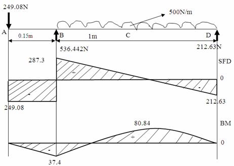
Figure 2. Shear force and bending moment diagrams
Diameter of the Shaft
Choosing shaft material of 0.26 carbon steel cold drawn
with maximum permissible working stress, ![]() of 84 [MPa] (ASME CODE) [3]. The equivalent bending moment, Me
and the diameter, d [mm] are related using the equation below:
of 84 [MPa] (ASME CODE) [3]. The equivalent bending moment, Me
and the diameter, d [mm] are related using the equation below:
|
|
(36) |
where d [m] is the diameter of the shaft. The choice of mild steel is made because of its light weight, strength and easy machinability.
Results and Discussion
The necessary design parameters needed for the fabrication of the industrial poultry feed tumble mixer was computed using MS Excel. The results are shown in table 1. The prototype of the design to produce 50kg of poultry feed was fabricated to be used in experimental mixing tests.
Table 1. Design parameters
|
Parameters |
Symbols |
Unit |
Value |
|
Trough design: |
|||
|
Volume of rec. box |
Vr |
m3 |
0.0846 |
|
Volume of cylinder |
Vc |
m3 |
0.059069 |
|
Total volume |
Vt |
m3 |
0.143669 |
|
Area of rec. box |
Ar |
m2 |
0.5560 |
|
Area of cylinder |
Ac |
m2 |
0.5907 |
|
Total area of trough |
At |
m2 |
1.1467 |
|
Volume of material |
Vm |
m3 |
0.002293 |
|
Mass of mixing trough |
mt |
Kg |
18.00005 |
|
Weight of empty trough |
W |
N |
176.580491 |
|
Weight of filled trough |
Wt |
N |
676.580491 |
|
Blade design: |
|||
|
Tangential load on blades: |
|
|
|
|
Blade x |
Wtx |
N |
89.05 |
|
Blade y |
Wty |
N |
89.05 |
|
Blade z |
Wtz |
N |
89.05 |
|
Normal load exerted on blades: |
|
|
|
|
Blade x |
Wnx |
N |
102.829099 |
|
Blade y |
Wny |
N |
102.829099 |
|
Blade z |
Wnz |
N |
102.829099 |
|
Normal vertical load exerted on blades: |
|
|
|
|
Blade x |
Wnvx |
N |
89.05 |
|
Blade y |
Wnvy |
N |
89.05 |
|
Blade z |
Wnvz |
N |
89.05 |
Table 1. Design parameters -continue
|
Normal load acting horizontally: |
|
|
|
|
Blade x |
Wnhx |
N |
51.4145497 |
|
Blade y |
Wnhx |
N |
51.4145497 |
|
Blade z |
Wnhx |
N |
51.4145497 |
|
Bending moment on blades (Vert. load): |
|
|
|
|
Blade x |
Mcvx |
Nm |
17.81 |
|
Blade y |
Mcvy |
Nm |
17.81 |
|
Blade z |
Mcvz |
Nm |
25.3370901 |
|
Bending moment on blades (Hori. Load): |
|
|
|
|
Blade x |
Mchx |
Nm |
107.2884 |
|
Blade y |
Mchy |
Nm |
204.621 |
|
Blade z |
Mchz |
Nm |
237.7866 |
|
Resultant bending moment on blades: |
|
|
|
|
Blade x |
Mcxe |
Nm |
108.756595 |
|
Blade y |
Mcye |
Nm |
205.39462 |
|
Blade z |
Mcze |
Nm |
239.132673 |
|
Shaft design: |
|
|
|
|
Speed of driven pulley |
N2 |
Rpm |
800 |
|
Centre distance |
C |
M |
0.425 |
|
Length of open belt |
L |
M |
1.558 |
|
Torque on shaft |
To |
Nm |
14.245 |
|
Maximum bending moment |
Mmax |
Nm |
68960 |
|
Diameter of shaft |
d |
M |
0.03 |
|
Capacity of drum |
V |
m3 |
0.167834 |
Proper design analysis was carried out on the machine to avoid failure on both the blades and the shaft. The resultant bending moment on the individual blades were computed separately to know the effect of the load on the blades and the machine was designed to be able to withstand stresses exerted by the load on its blades by applying factor of safety in our design computations. From the results obtained, blade Z has the highest bending moment and proper design considerations were employed to tackle the effect of high bending moment on the blade to avoid failure.
The shaft design was done considering the speed of the driven pulley which is the speed of the pulley attached to the shaft of the tumble mixer, that is, the speed needed to produce the uniform mixing effect to avoid carryover in the mixing drum. The centre distance between both pulleys was also calculated to be able to get the actual length of belt needed for the design process. The shaft was designed to withstand direct, bending and torsional stresses as a result of the combination of both direct and fluctuating loads. The diameter of the shaft was computed to get the needed size which was then used in the fabrication process.
Conclusions
An automated industrial poultry feed tumble mixer was designed and fabricated, a prototype of the mixer 0.78 [m2] collector areas was fabricated to be used in experimental mixing tests based on preliminary design computations and investigations. The fabricated mixer was used to mix poultry feed ingredients under controlled conditions yielding an acceptable output hereby saving time and energy. The machine is safe to use and efficient. The machine was cost effective because the design and fabrication were done locally.
Acknowledgements
The authors would like to gratefully acknowledge Prof. Oko, C.O.C. of the department of mechanical engineering, faculty of engineering, University of Port Harcourt for his expert supervision and constructive criticism during the development of this research work.
References
1. Akpobi J.A, Ovuworie G.C., Computer-Aided Design of the Critical Speed of Shafts, Journal of Applied Science and Environmental Management, 2008, 12, p. 79-86.
2. Akpobi J.A., Ardey M., Computer-Aided Design for Machine Vibrations, Technical Transactions of the Nigerian Institution of Production Engineers, 2002, 7(3), p. 41-62.
3. Akpobi J.A, Lawani I.A., Computer Aided Design of Flywheels, Advances in Engineering Software (Elsevier Publishers), 2006, 37(4), p. 222-235.
4. Okojie V.A., Software Approach in Solving Shaft Design Problems, Project Solutions Domain Journal of Mechanical Engineering, 2011, 1, p. 15-28.
5. Ear T.S, Johnson B.P., Production engineering, Third Edition, Tata Mcgraw Hill Company Limited, New Delhi, 2007.
6. Khurmi R.S., Gupta J.K., A Textbook of Machine Design, Fourteenth Edition, S. Chand and Company Limited, New Delhi, 2005.
7. Suresh P., Carry-Over, Prevention in Machines, Machine Design Development, 1997, 5, p. 345-349.
8. Deane A., Developing Mathematics Creativity with Spreadsheets, Journal of Korea Society of Math. Educ., 2005, 9(3), p. 187-201.
9. Diemuodeke E.O., Momoh O.L.Y., Design and Fabrication of a Direct Natural Convection Solar Dryer for Tapioca, Leonardo Electronic Journal of Practices and Technologies, 2011, 18, p. 95-104.
10. Oko C.O.C., Diemuodeke E.O., Analysis of Air-Conditioning and Drying processes Using Spreadsheet Add-In for Psychrometric Data, Journal of Engineering Science and Technology Review, 2010, 3(1), p. 7-13.
11. Rajput R.K., Strength of Materials, Fourth Edition, S. Chand and Company Limited, New Delhi, 2006.
12. Ashby F.M., Jones R.B.H., Engineering Materials: An Introduction to Their Properties and Application, Second Edition, Butterworth Heinemann, Oxford, 2002.