Digital Phase Locked Loop Induction Motor Speed Controller: Design and Experiments
Mouna BEN HAMED* and Lassaad SBITA
National Engineering School of Gabès - ENIG, Zrig 6029 Gabès- Tunisia
E-mail(s): benhamed2209@yahoo.fr; lassaad.sbita@enig.rnu.tn
* Corresponding author: Phone: +216 95 851 313; Fax: +216 75 392 190
Abstract
Phase locked loop (PLL) is a technique which has contributed significantly toward the technology advancement in communication and motor servo control systems. Inventions in PLL schemes combining with novel integrated circuit have made PLL devices important system components. The development of better modular PLL integrated circuit is continuing. As a result, it is expected that it will contribute to improvement in performance and reliability for communication and servo control systems. In this paper, the study of the speed control of induction motor (IM) drives using digital phase locked loop (DPLL) is discussed. A novel scalar law which compensates the slip frequency loop calculation is proposed. The overall investigated system is tested using a 1Kw IM. Different speed trajectories are considered covering the realistic operating range. The PLL IM drives controller is implemented all around the most popular integrated circuits 4046 PLL. Experimental results are presented to show the performance of the investigated control system.
Keywords
Phase locked loop; Induction motor; Scalar law; Speed control; Slip compensation.
Introduction
Three phase IMs are the most widely used electrical motors due to their ruggedness, robustness and low cost [1, 2]. It can be operated directly from the main. However, variable speed and often better energy efficiency are achieved by means of a frequency converter between the main and the motor. A typical frequency converter consists of a rectifier, a voltage stiff dc link and a pulse width modulated (PWM) inverter. The inverter is controlled with a digital signal processor (DSP).
A simple way to control the IM is to adjust the magnitude of the stator voltage proportionally to its frequency. This open loop method known as the scalar control or constant voltage per hertz law is still used for low cost frequency converter due to its important advantages [2, 3]; a speed sensor isn’t needed. The knowledge of the motor parameters is not necessary either implying that the strategy is robust. However, the dynamic performance and the speed accuracy are poor [4]. To improve the accuracy of the rotor speed in control strategy, the main idea is based on the slip frequency compensation [5]. It can be divided into two classes. The first is based on the addition of frequency compensation in open loop control strategy. While, for the second, the accuracy of the rotor speed is improved with slip regulation in closed loop speed drives.
Improved techniques using the phase component of the stator current and a compensation proportional to a slip signal have been proposed [6]. Vector compensation was proposed in [7], but it requires both voltage and current sensors and accurate knowledge of machine inductances. More recently, a scalar control scheme was proposed [8]. In this scheme, the flux magnitude is derived from the current estimation. In [9], the slip compensation was based on a linear torque-speed assumption which led to large steady-state errors in speed for high load torques. A linearized frequency compensation control based on an ideal IM was proposed in [10]. The frequency compensation is based on an estimation of the air gap power and a nonlinear relationship between slip frequency and air gap power is carried out in [5]. Since these methods are based on slip computation loop, the computation time increases which decrease the performances of the overall control system.
To improve these performances of the open loop scalar IM drives, a feedback speed control signal is added. Conventional speed closed loop control with slip frequency regulation to improve the speed accuracy in open loop control strategy is based on the well-known motor frequencies equation [11]. Here, the motor speed is compared to the target one and the error generates the slip frequency command through a controller and a limiter. The slip frequency is added to the rotor speed to generate the frequency and voltage commands as shown in Figure. 1.
Figure 1. Bloc diagram of conventional scalar strategy in IM.
The high performance of the speed regulation depends on the performance of the speed controller. Researchers have used various types of closed loop controllers for the IM rotor speed. Among these controllers, the proportional integral derivative controllers are widely used in the outer speed loop [12, 13]. However, the use of this type of controller is more sensitive to parameter variation [14, 15]. To overcome this problem, adaptive [16, 17] and robust [18-20] control laws were used. The adaptive control imposes a very computation burden while H∞ robust control requires the knowledge of the disturbances boundaries [18]. The sliding mode control is also used in the speed loop [21]. The high chattering and switching frequency limit the use of this controller [22, 23]. Recently, speed controllers based on artificial intelligence techniques such as fuzzy logic and neural network based controllers have been proposed [24, 25]. Since these approaches do not require the knowledge of a mathematical machine model, the algorithm would remain robust despite of parameter deviations and noise measurement [26, 27]. However, the computation expenses and the requirement of expert knowledge for the system setup have seriously restricted their applications in practice. In [28], an internal model controller (IMC) is developed for the feedback of the scalar controlled IM. This IMC controller has the advantage of robustness, ease of design and good responses. In some applications, a precise speed is required. Excellent speed regulation can be achieved with a DPLL. In [29], Moore found that this technique has significant ability to obtain precise speed regulation. When the feedback signal of the IM speed is synchronized with a reference signal, perfect signal speed regulation can be realized about 0.02% to 0.1% of the steady state accuracy which is difficult to obtain by conventional closed loop system scheme.
In the research work carried out in [30], the speed control of a three phase squirrel cage IM fed by triacs devices in the lines is described. The speed closed loop regulation of the system is then investigated with a DPLL scheme. In [31], the study of the IM DPLL speed control loop is discussed. The IM is fed with thyristors power inverter. Here, the DPLL is established using digital and analogical circuits. In [32], the authors have developed an inverter fed IM drive using the PLL speed controller. A conventional closed loop speed control with slip regulation to improve the speed accuracy in open loop control strategy is achieved.
In this research paper, a novel and simple slip frequency compensation technique was proposed. Since the output of the speed control feeds out the synchronous angular speed. This method compensates the slip frequency computation loop. The higher performance of the proposed method depends on the performance of the speed controller. As the DPLL has the ability to obtain perfect speed regulation, it is used in speed loop regulation. The DPLL is implemented using the inexpensive integrated circuit 4046. Experimental results are presented to show the improvement in performance of the proposed method.
Material and Method
PLL Concepts
PLL is a feedback loop where a voltage controlled oscillator (VCO) can be automatically synchronized to a periodic input signal. The basic PLL has three components connected in a feedback loop [1] as shown in the block diagram of Figure. 2: a VCO, a Phase Detector (PD) and a Low Pass Filter (LPF).
Figure 2. Bloc diagram of the PLL.
The VCO is an oscillator whose frequency fosc is proportional to input voltage. The voltage at the input of the VCO determines the frequency of the periodic signal at the output of the VCO. The output of the VCO and a periodic input signal (the reference) are inputs to the PD. When the loop is locked on the input signal, the VCO output frequency is exactly equal to fi the reference one. It is also said that the PLL is in the locked condition. The PD produces a signal proportional to the phase difference between the reference signal and the VCO output signal. The PD output is altered by a LPF. The loop is closed by connecting the filter output to the VCO input. The output voltage of the filter is used to control the frequency of the VCO. A basic property of the PLL is that it attempts to maintain the frequency lock between the VCO output and reference signal even if the frequency of the input signal varies in time [39].
Suppose that the PLL is in the locked condition, and that the frequency of the incoming signal increases slightly. The phase difference between the VCO signal and the incoming signal will begin to increase in time. The filter output voltage increases, and the VCO output frequency increases until it matches the reference frequency, thus keeping the PLL in the locked condition. The range of frequencies from minimal to maximal value where the PLL remains in the locked condition is called the lock range of the PLL [36, 37].
If the PLL is initially locked and input signal frequency becomes smaller than fmin, or if input signal frequency exceeds fmax, the PLL fails to keep the VCO frequency equal to input signal frequency, and the PLL becomes unlocked. When the PLL is unlocked, the VCO output oscillates at the frequency f0 called the center frequency, or the VCO free-running frequency. The lock can be established again if the incoming signal frequency gets close enough to f0. The range of frequencies f0 = f0 - fc to f0 = f0 + fc such that the initially unlocked PLL becomes locked is called the capture range of the PLL [35]. The capture range 2fc depends on the characteristic of the loop filter [36]. For the used filter, an approximate implicit capture range expression can be founded as:
|
|
(1) |

If the capture range is much larger than the cut off frequency fp of the filter, fc/fp>1, (1) can be written as:
|
|
(2) |
where: K0 is the VCO gain or the frequency sensitivity.
Thanks to the rapid development of technology, the PLL is implemented using the integrated circuit systems. The most used integrated circuit is the well-known 4046 chip [34].
Proposed Scheme of the Drive System
The block diagram of the proposed IM drive system is shown in Figure. 3.
Figure 3. Bloc diagram of the novel scalar strategy IM DPLL speed control.
The closed loop control scheme of the induction motor is based on the DPLL rotor speed controller. The strategy to assume the decoupling of the IM is the scalar one applied to voltage source inverter.
Scalar Control Strategy Principle
In steady state operation, the IM flux is approximately equal to the ratio [34]. The correct utilization of the machine magnetic characteristic is done by maintaining the flux constant below the base speed [1, 4]. In figure 4 is present a single phase equivalent circuit.
Figure 4. Single phase equivalent circuit of the induction machine.
Based on the single phase equivalent circuit (Figure. 4), the electromagnetic power is defined as [39]:
|
|
(3) |

By assumption, we neglect the stator resistance. Then, we get:
|
|
(4) |

where fr is the slip frequency. The mechanical dynamics of the IM is expressed as:
|
|
(5) |
If we give the zero value to the load torque (TL) and we neglect 2πNe, the transfer function between the rotor speed ω and synchronous speed ωs is given as:
|
|
(6) |
where p is the number of poles pair, f is the viscous coefficient, τ is the time constant and k is the static gain of the system.
It can be seen from equation (6) that the rotor speed is controlled with the synchronous angular speed. Therefore, to compensate the slip angular speed when a disturbance occurred, a speed controller must be added. Compared to conventional scalar control, this novel scalar strategy compensates the frequency slip calculation loop leading to a reduced calculation time. In general, excellent slip angular compensation is needed. This feature can be achieved by DPLL controller as shown in Figure. 3.
DPLL IM Speed Control
The overall system block diagram of 4046 PLL IM speed control is given in Figure. 3. This system is roughly classified into two parts: the control and the power parts. The control part is consisting mainly of 4046 PLL and a scalar control unit. A simple positive supply voltage is needed for the chip. The positive supply voltage VDD is connected to pin 16 and the ground is connected to pin8. The reference square wave signal goes to the input of an internal amplifier at the pin 14 of the chip. The reference signal must be a square wave with a 50% duty cycle. Therefore, to obtain this target signal, a direct voltage is fed to pin 9 (the input of the 4046 VCO) to give at its output (pin 4), a square wave signal representing the target rotor speed. The VCO requires one external capacitor C1 and one or two external resistor (R1 or R1 and R2).
Resistor R1 and capacitor C1 determine the frequency range of the VCO and resistor R2 enables the VCO to have a frequency offset if required. The output motor speed is encoded as a digital pulse train. The encoder frequency is feedback at pin 3 and compared to the target frequency received at pin 4 by the PD [38]. The used PD in this application is the comparator I of 4046. It is simply an XOR logic gate with logic down output when the two inputs are either high or both low and the logic up otherwise. The output of the phase detector is proportional to the phase error between the two inputs [36, 37]. The PD output is filtered by an external LPF [38]. The obtained filtered voltage is proportional to the synchronous frequency which feeds the scalar unit. Compared to the conventional scalar law [36], the proposed scalar law compensates the slip frequency calculation loop.
The used filter has the transfer function defined as [36]:
|
|
(7) |
where fp=ωp/2π is the cut off frequency of the filter. If fp<2fi, the output of the filter is approximately equal to the dc component of the PD output [32].
The purpose of the low pass filter is to pass the DC component and low frequency at the output of the PD and to attenuate high frequency ac components [36], [45] and [46]. In practice, the high frequency components are not completely eliminated and can be observed as high frequency ac ripple around the dc component [36]. The obtained signal at the output of the low pass filter feeds the scalar control unit card to drive the IGBT’s transistor of the voltage inverter supply (VSI).
Results and Discussion
The investigated DPLL IM speed regulation is built and tested using a 1kw squirrel cage IM. Figure. 5 shows the experimental set up drive system of the hardware configuration. A VSI utilizes a full bridge thyristor rectifier as a DC bus voltage link. The power circuit part is composed of intelligent power modules (IPMS). IPMS are constructed with insolated gate bipolar transistors (IGBTs). The pulse width modulation (PWM) signals to control the power modules are generated by the scalar control card equipped with a digital processor. An incremental encoder position sensor delivering 1024 pulses per revolution is mounted on the rotor shaft to measure the rotor speed. The DPLL is built around the 4046 integrated circuit system. A DC generator as a load is coupled with the IM.
We have tested the investigated system for various ranges of target rotor speeds. For each test, we present the rotor speed, the output of the incremental encoder and the 4046 VCO output.
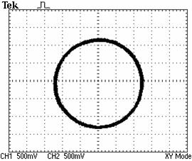
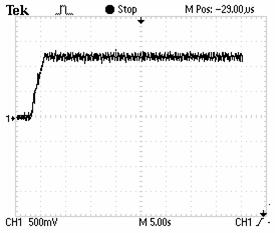
Obtained experimental results are given in Figures 6 to 17. Excellent steady state frequency has been obtained especially at high and average speeds proving the high performances of the rotor speed regulation using the DPLL. It can be seen from Figures. 8 and 10 that the control voltage which is proportional to the synchronous frequency in factor of 10 converges at steady state to the rotor speed (50Hz) indicating that excellent slip frequency compensation is established up on the novel scalar control. Besides, the trajectory of the stator flux presented at Figure. 11 show that the decoupled flux is achieved.
Compared with the other control laws, the present scheme is somewhat simpler, cheaper and provides speed control with high precision. The LPF used to extract the DC component has a cut off frequency which depends on the frequency of the reference train pulse. However, the reference train pulse frequency is variable. Therefore, for each reference train pulse frequency correspond a cut off frequency. In this work, the latter is fixed at a constant value. The drawback of this is shown from the results obtained at very low speeds (Figures 16 and 17).
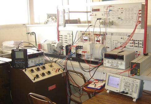
Figure 5. An experimental set up view.
The overall system with a 1kw squirrel IM has been designed and tested in the laboratory over the entire speed range. Obtained experimental results show that a precise speed regulation is achieved at steady state. The investigated drive combines excellent speed regulation and improved performance of constant Volt per Hertz law with novel frequency slip compensation.
|
|
|
|
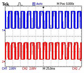
Figure 6. Evolution of Command signals of the inverter first bridge. |
Figure 7. Evolution of Command signals of the first IGBT of the first and second inverter bridges. |
|
. |
|
|
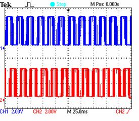
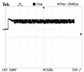
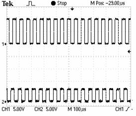
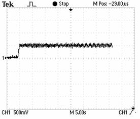
Figure 8. Evolution of IM speed for a target frequency of 25KHZ. |
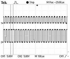
Figure 9. Evolution of the incremental encoder and the target frequency (Output of 4046 VCO) for a target frequency of 25KHZ. |
|
|
|
|
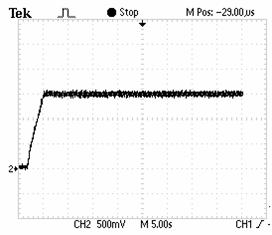
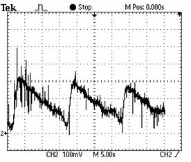
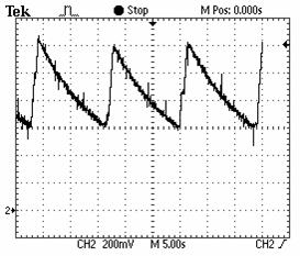
Figure 10. Evolution of the control law (the output of the low pass filter) for a target frequency of 25KHZ. |
Figure 11. Stator fux vector
trajectory in |
|
|
|
|
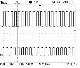
Figure 12. Evolution of IM speed for a target frequency of 11.9KHZ. |
Figure 13. Evolution of the incremental encoder and the target for a target frequency (Output of 4046 VCO) for a target frequency of 11.9 KHz. |
|
|
|
|
Figure 14. Evolution of IM speed for a target frequency of 8.33KHZ. |
Figure 15. Evolution of the incremental encoder and the target frequency (Output of 4046 VCO) for a target frequency of 8.33KHZ. |
|
|
|
|
Figure 16. Evolution of the of IM speed at low target speed (150rpm). |
Figure 17. Evolution of the control law (LPF output) at low target speed (150rpm). |
Conclusions
All high performances scalar controlled IM drives require accurate rotational speed information for feedback control. This information is mainly provided by incremental encoder. The use of this sensor implies more electronics and high cost. To overcome these problems, a speed observer can be included in the control loop. Thanks to high performance of the PLL techniques, it can be used to reconstruct the IM speed. The PLL sensorless novel scalar strategy IM speed controller with an adaptive LPF cut off frequency will be the subject for further studies.
References
1. Ben Hamed M., Sbita L., A Digital Phase Locked Loop Speed Control of Three Phase Induction Motor Drive: Performances Analysis, International Journal of Energy and Power Engineering: EPE Journal, 2011, 3, p. 61-68.
2. Bojoi R., Guglielmi P., Pellegrino G.M., Sensorless direct field oriented control of three phase induction motor drives for low cost applications, IEEE Transaction on Industrial Applications, 2009, 44, p. 475-481.
3. Ben Hamed M., Sbita L., Internal model controller of an ANN speed sensorless controlled induction motor drive, Journal of Applied Science (JAS), 2007, 7, p. 1456-1466.
4. Xiang-Dong S., Kang-Hoon K., Byung-Gryu Y., Matsui M., Fuzzy logic based V/f control of an induction motor for a DC grid power leveling system using flywheel energy storage equipment, IEEE Transactions On Industrial Electronics, 2009, 8, p. 3161-3168.
5. Hinkkanen M., Flux estimators for speed sensorless induction motor drives, PhD. dissertation, Helsinki University, 2004.
6. Alfredo M.C., Thomas A.L., Novotn D.W., A new V/f control method capable of high performance regulation at low speeds, IEEE Transaction on Industrial Applications, 1998, 34, p. 813-821.
7. Abbondanti A., Method of flux control in induction motors driven by variable frequency, variable voltage supplies, The IEEE International Conference on Industry Society ~IAS 1977~, 1977.
8. Abbondanti A., Flux control system for controlled induction motors, U.S. Patent 3 909 687, 1975.
9. Green T.C., William B.W., Control of induction motor using phase current feedback derived from the DC link, The IEEE International Conference on Electric Power Energy ~EPE 1989~, 1989.
10. Xue Y., Xu X., Habetler T.G., Divan D.M., A low cost stator oriented voltage source variable speed drive, The IEEE International Conference on Industry Society ~IAS 1990~, 1990.
11. Koga K., Ueda R., Sonoda T., Constitution of V/f control for reducing the steady state speed error to zero in induction motor drive system, The IEEE International Conference on Industry Society ~IAS 1990~, 1990.
12. Bose B., Power Electronics and Motor Drives: Advances and Trends, Elsevier Inc., 2006.
13. Rubai A., Castro-Stitiriche M.J., Ofli A.R., DSP based laboratory implementation of hybrid fuzzy PID controller using genetic optimization for high performance motor drives, IEEE Transaction on Industrial Applications, 2008, 44, p. 1977-1986.
14. Cong S., Liang Y., PID like neural network like non-linear adaptive control for uncertain multi variable motion control systems, IEEE Transactions on Industrial Electronics, 2009, 56, p. 3872-3879.
15. Missiala M., Vafakhah B., Salmon J., Knight A.M., Fuzzy self-tuning speed control of an indirect field-oriented control induction motor drive, IEEE Transaction on Industrial Applications, 2008, 44, p. 1732-1740.
16. Huang H.P., Yong, J.L., Chang T.H., Development and fuzzy control of a pipe inspection robot, IEEE Transactions on Industrial Electronics, 2010, 57(3), p. 1088-1095.
17. Orlowska-Kowalska T., Dybkousi M., Szabat K., Adaptive sliding mode neuro-fuzzy control of two mass induction motor drive without mechanical sensors, IEEE Transactions on Industrial Electronics, 2009, 57 (2), p. 553-564.
18. Szabat K., Orlowska-Kowalska T., Dybkousi M., Adaptive sliding mode neuro-fuzzy control of two mass induction motor drive without mechanical sensors, IEEE Transactions on Industrial Electronics, 2009, 56(10), p. 4038-4042.
19. Katayama S., Yubai K., Hirai J., Iterative design of the reduced order weight and controller for the H? loop shaping method under open loop magnitude constraints for SISO systems, IEEE Transactions on Industrial Electronics, 2009, 56(10), p. 3854-3863.
20. Kian Hoong K., Yung Chung C., Lan S., Model based H? control of unified power quality conditioner, IEEE Transactions on Industrial Electronics, 2009, 56(7), p. 2493-2504.
21. Yalsh I., Shaked U., Neuro adaptive H? estimation and its application to improved tracking in GPS receivers, IEEE Transactions on Industrial Electronics, 2009, 56(3), p. 642-647.
22. Betron B., Ahmed-Ali T., Benbouzid M., High order Sliding mode control of variable speed wind turbines, IEEE Transactions on Industrial Electronics, 2009, 56(9), p. 3314-3321.
23. Xinghuo Y., Kaynak O., Sliding mode control with soft computing: a survey, IEEE Transactions on Industrial Electronics, 2009, 56(9), p. 3275-3285.
24. Utkin V.U., Sliding mode in control and optimization, Berlin: Springer, 1992.
25. Ben Hamed M., Sbita L., Abboud W., Neural Networks for controlled Speed Sensorless Direct Field Oriented Induction Motor Drives, International Journal of Electrical Engineering, 2008, 8(11), p. 84-96.
26. Sbita L., Ben Hamed M., Fuzzy Controller and ANN Speed Estimation For Induction Motor Drives Speed Sensorless Induction Motor Drives, the 4th IEEE International Multi-Conference on Systems, Signals & Devices ~SSD2007~, Hammamet, Tunisia, March 19-22, 2007, in CD conference.
27. Xiang-Dong S., Kang-Hoon K., Byung-Gryu Y., Matsuin M., Fuzzy logic based V/f control of an induction motor for a DC grid power leveling system using flywheel energy storage equipment, IEEE Transactions on Industrial Electronics, 2009, 56(8), p. 3161-3168.
28. Liangyong W., Tianyou C., Lianfei Z., Neural network based terminal sliding mode control of robotic manipulators including actuator dynamics, IEEE Transactions on Industrial Electronics, 2009, 56(9), p. 3296-3304.
29. Moore A.W., Phase locked loops for motor speed control, IEEE spectrum, 1973.
30. Kenly W.L., Bose. B.K., A triac speed control of three phase induction motor with phase locked loop regulation, IEEE Transactions on Industrial Electronics, 1976, IAI-12(5), p. 492-498.
31. Moffat R., Sen P., Younker R., Digital phase locked loop for induction motor Steady state and stability analysis of an analog type phase locked loop dc motor control system, IEEE Transactions on Industrial Applications, 1979, IAI-15(2).
32. Sen P.C., Macdonald. M., Stability analysis of induction motor drives using phase locked loop control system, IEEE Transactions on Industrial Electronics, 1980, IECI-27(3).
33. Ismail N.M.H., Othman. M., Low power phase locked loop frequency synthesizer for 2.4 GHz band zigbee, American Journal of Engineering and Applied Sciences, 2009, 2(2), p. 337-343.
34. Hsieh G.C., Hung. J.C., Phase-locked loop techniques. A survey, IEEE Transactions on Industrial Electronics, 1996, 43(6), p. 609-615.
35. Takano A., Quick-response torque-controlled induction motor drives using phase-locked loop speed control with disturbance compensation, IEEE Transactions on Industrial Electronics, 1996, 43(6), p. 640-646.
36. Al-Taha R.A., Jassim R.S., Stability analysis of a linear discrete data induction motor drive using phase locked loop (PLL), the 2nd IEEE International Multi-Conference on Systems, Signals & Devices ~SSD2005~, 2005, Sousse, Tunisia.
37. Lagutere T., Conceptions et modalisations d'oscillateurs et de leurs boucles verrouillage de phase associes pour des applications de radiocommunications mobiles professionnelles, PhD. dissertation, Poitiers Univ., 2005.
38. Aleksandar H.Y., Test generator for examination of PLL and DDS systems, Electronics, 2008, p. 72-76.
39. Boldea I., Nasar S.A., Electric Drives, Taylor and Francis Group, 2005.