Comparing Effects of TCR and TSC on MHO Distance Protection Setting in 400 kV Algerian Transmission Line
Mohamed ZELLAGUI* and Abdelaziz CHAGHI
LSP-IE Research Laboratory, Department of Electrical Engineering, University of Batna
Campus CUB, Street Med El Hadi Boukhlouf, 05000, Batna, Algeria
E-mail(s): m.zellagui@ymail.com; az_chaghi@univ.batna.dz
* Corresponding author: Phone: +213 670 09 84 03; Fax: +213 33 81 51 23
Abstract
This paper presents a study on the performances of distance relays setting in 400 kV in Eastern Algerian transmission networks at Sonelgaz Group (Algerian company of Electrical and Gas) compensated by shunt Flexible AC Transmission System (FACTS). The facts are used for controlling transmission voltage, power flow, reactive power, and damping of power system oscillations in high power transfer levels. The effects of SVC devices i.e. Thyristor Controlled Reactor (TCR) and the Thyristor Switched Capacitors (TSC) insertion, on the total impedance of a transmission line protected by MHO distance relay are investigated. The modified setting zones protections for three forward zones (Z1, Z2 and Z3) have been calculated in order to improve the performances of distance relay protection and prevent circuit breaker nuisance tripping.
Keywords
Transmission Lin; Impedance; MHO Distance Relay; Setting Zones; Substance; Shunt FACTS; SVC Devices; TSR; TSC.
Introduction
In recent years, power demand has increased substantially while the expansion of power generation and transmission has been severely limited due to limited resources and environmental restrictions. As a consequence, some transmission lines are heavily loaded and the system stability becomes a power transfer-limiting factor. Flexible AC transmission systems (FACTS) controllers have been mainly used for solving various power system steady state control problems [1]. The literature shows an increasing interest in this subject for the last two decades, where FACTS devices are introduced in power systems to increase the transmitting capacity of transmission lines and provide the optimum utilization of the system capability. This is done by pushing the power systems to their limits [2-3]. It is well documented in the literature that the introduction of FACTS devices in a power system has a great influence on its dynamics. As power system dynamics changes, many sub-systems are affected, including the protective systems. Therefore, it is essential to study the effects of shunt FACTS devices on the protective systems, especially the distance protection, which is the main protective device at HV and EHV levels.
The application of SVC was initially for load compensation of fast changing loads such as steel mills and arc furnaces. Here the objectives are: increase power transfer in long lines [4], improve stability with fast acting voltage regulation [5], damping low frequency oscillations due to swing (rotor) modes [6] and damping sub-synchronous frequency oscillations due to torsion modes and over-voltages dynamic control [7]. Unlike the power system parameters, the controlling parameters of SVC devices, as well as their installation points could affect the measured impedance [8-13]. This variation has a direct effect on the protective zones settings for distance relays protected this line compensated. In the presence of shunt FACTS devices, the conventional distance characteristic such as MHO and quadrilateral are greatly subjected to mal-operation in the form of over-reaching or under-reaching the fault point. Therefore, the conventional characteristics might not be utilized satisfactorily in the presence of shunt FACTS devices [11,13].
In this paper, the three protection zones setting (Z1, Z2 and Z3) for a MHO distance relay based analytic method on a 400 kV single transmission line installed at eastern Algerian electrical network is considered.
The aim of this research was the investigation concerns TCR and TSC shunt FACTS devices, for different values of firing angle (α) for injected reactive power ± 60 MVar shunt compensation on midline transmission high voltage.
Material and Method
MHO Distance Relay in Transmission Line
MHO Distance protection is so called because it is based on an electrical measure of distance along a transmission line to a fault [14]. The distance along the transmission line is directly proportional to the series electrical impedance of the transmission line (ZL) between busbar A and B as shown in figure 1. The distance protection measures distance to a fault by means of a measured voltage to measured current ratio computation [15-16]. The philosophy of setting relay at Sonelgaz Group [16-17] is three forward zones (Z1, Z2 and Z3) for protection the line HV between busbar A and B with total impedance ZAB.
|
|
|
Figure 1. Principal operation of MHO distance relay |
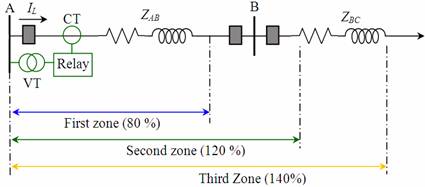
First Zone: It is normal practice to adjust the first zone relays (Z1) at A to protect only up to 80% of the protective line AB. This is a high speed unit and is used for the primary protection of the protected line. Its operation is instantaneous. This unit is not set to protect the entire line to avoid undesired tripping due to over reach. Over reach may occur due to transients during the fault condition.
Second Zone: Is set to cover about 20% of the second line (BC). The main object of the second zone unit is to provide protection to the end zone of the first section which is beyond the reach of the first unit. The setting of the second unit is so adjusted that it operates the relay even for arcing faults at the end of the line. To achieve this, the unit must take care beyond the end of the line. In other words its setting must take care of under reach caused by arc resistance. Under reach is also caused by intermediate current sources, errors in CT, and VT and measurement performed by the relay. To take into account the under reaching tendency caused by these factors, the normal practice is to set the second zone reach up to 20% of the shortest adjoining line section. The protective zone of the second unit is known as the second zone of protection. The second zone unit operates after a certain time delay. Its operating time is 0.3 sec.
Third Zone: Is provided for back-up protection of the adjoining line. Its reach should extend beyond the end of the adjoining line under the maximum under reach, which may be caused by arcs, intermediate current sources and errors in CT, VT and measuring unit. The protective zone of the third stage is known as the third zone of protection. The setting of the third zone covers the first line i.e. the protected line plus the longest second line plus 20% of the third line. The time delay for the third unit is usually 1 to 1.5 sec.
The setting zones for protected transmission line without shunt FACTS devices are expressed by [16-17]:
|
Z1 = R1 + jX1 = 80%ZAB = 0,8.(RAB + jXAB) |
(1) |
|
Z2 = R2 + jX2 = RAB + jXAB + 0,2.(RBC + jXBc) |
(2) |
|
Z3 = R3 + jX3 = RAB + jXAB + 0,4.(RBC + jXBc) |
(3) |
The total impedance of electrical transmission line AB measured by MHO distance relay is given by:
|
ZAB = KZ·ZL = (KVT/KCT)·ZL |
(4) |
where: KVT and KCT are ratio of voltage and current transformers respectively.
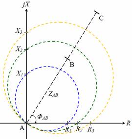
The characteristic curves X(R) [18] for MHO distance relay are represented in figure 2.
|
|
|
Figure 2. Settings zones of MHO distance relay |
The presence of SVC devices has a direct influence on the total impedance of the protected line (ZAB). Connected at midline point of the line, the SVC is considered as a reactor (XSVC) and lead to the new setting zones which can be expressed by [16-17]:
|
Z1 = 0,8.[[(ZAB/2) // Xsvc] + ZAB/2] |
(5) |
|
Z2 = [(ZAB/2) // Xsvc] + ZAB/2 + 0,2·ZBC |
(6) |
|
Z3 = [(ZAB/2) // Xsvc] + ZAB/2 + 0,4·ZBC] |
(7) |
Substance of Static VAR Compensator (SVC)
The SVC is an early type of the shunt connected FACTS devices as shows in figure 3. The SVC controls voltage where it is connected by adjusting its susceptance in order to supply or absorb the required reactive power (QSVC) [3, 19]. SVC consists of TCR and a set of TSC in parallel, and an associated controlling system. The controlling system operates to regulate the voltage at its connecting point, according to its controlling strategy within its operational limits.
|
|
|
Figure 3. Structures of SVC devices |
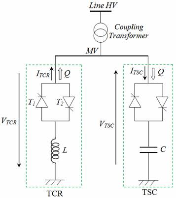
The overall action of the thyristor controller on the linear reactor of the TCR and capacitor of the TSC is to enable the reactor to act as a controllable susceptance, in the inductive mode, which is a function of the angle α [19]. The figure 4(a) and 4(b) represent the substance for TCR and TSC respectively.
|
|
|
|
a) |
b) |
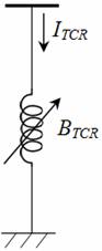
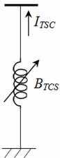
Figure 4. Injected susceptance of SVC devices
The current ITCR directly related to the firing angle of thyristors (α), which was varied between 90° and 180° [1-3,19]. The value of the substance BTCR will be represented by the equation [3,19]:
|
BTCR (α) = BL.max.[1 - (2·α/π) - sin(2·α)] / π |
(8) |
where:
|
BL.max = 1/L·ω |
(9) |
For the TSC, the expression BTCS is defined in reference [1-3,19] by:
|
BTCS (α) = BC.max.[1-(2·α/π) - sin(2·α)] / π |
(10) |
where:
|
BC.max = -C·ω |
(11) |
Case Study
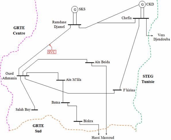
The figure below represents the power system studied in this paper and is the 400 kV, 50 Hz eastern Algerian electrical transmission networks at SONELGAZ group. The MHO distance relay is located in the busbar A at Ramdane Djamel substation (Skikda) to protect transmission line between busbar A and busbar B at Oued El Athmanai substation (Mila), the busbar C at Ain M’lila substation (Oum El Bouaghi).
The shunt FACTS study type SVC is installed in the midpoint of the line protected by a MHO distance relay as represented in figure 5. The parameters of the transmission line and installed SVC device are summarized in the appendix.
|
|
|
Figure 5. Electrical networks study in presence SVC devices |
Results and Discussions
The characteristic curves of the SVC compensator (TCR and TSC) used in this network are indicated by figure 6(a) and figure 6(b) respectively.
|
|
|
a) BTCR = f (α)
|
|
|
|
b) BTSC = f (α) |
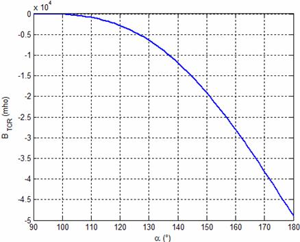
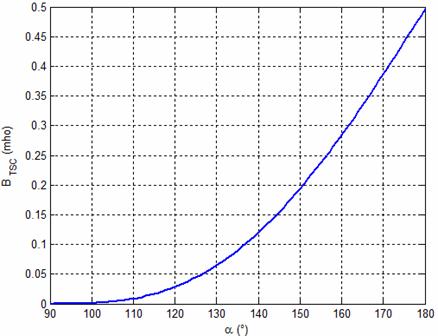
Figure 6. Characteristic curves of the installed SVC
Figures 7 and 8 represented the impact of the variation angle α in the presence of TCR and TSC on the total reactance XAB and resistance RAB respectively measured by MHO distance relay.
|
|
|
Figure 7. Impact of the firing angle α on XAB measured by distance relay
|
|
|
|
Figure 8. Impact of the firing angle α on RAB measured by distance relay
|
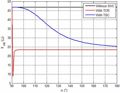
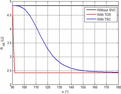
As can be seen the presence of TCR and TSC has a direct influence on the parameters of the protected line XAB and RAB. The total impedance measured by the distance relay without SVC devices is equal 4,8407 + j 46,8048 (Ω), the settings zones are summered in table 1.
Table 1. Setting Distance Relay without SVC Devices
|
Setting zones |
X (Ω) |
R (Ω) |
|
First Zone |
1,8722 |
0,1936 |
|
Second Zone |
2,6172 |
0,2707 |
|
Third Zone |
2,8943 |
0,2993 |
Setting Relay on Presence TCR
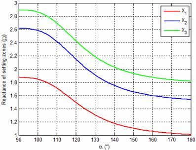
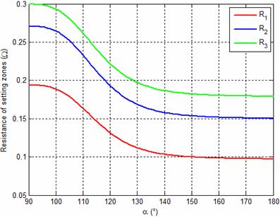
Figures 9 and 10 represented the impact of the firing angle variation on the settings zones reactance and resistance respectively for the protected transmission line.
|
|
|
Figure 9. Impact of the firing angle α on the reactance setting zones in the presence of TCR |
|
|
|
Figure 10. Impact of the firing angle α on the resistance setting zones in the presence of TCR |
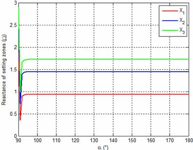
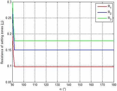
From figures 9 and 10, the setting of the three zones of protection is dependent on the angle α of the TCR.
Setting Relay on Presence TSC
Figures 11 and 12 represented the impact of the firing angle variation on the settings zones reactance and resistance respectively in the presence of the TSC compensator.
|
|
|
Figure 11. Impact of the firing angle α on the reactance setting zones in the presence of TSC
|
|
|
|
Figure 12. Impact of the firing angle α on the resistance setting zones in the presence of TSC |
As can be seen from figures 11 and 12 the setting of the three protection zones is dependent on the firing angle α of the TSC.
Conclusions
The results show the direct effects of SVC devices i.e. thyristors controlled reactor (TCR) and the thyristors switched capacitors (TSC) insertion, on the total impedance of a transmission line protected by MHO distance relay. The impact is investigated for different values of the thyristors firing angle.
As demonstrated these angles injected variable substance (BTCR or BTCS) in the protected line which results in direct impact on the total impedance of the protected line. In fact this effect varies the settings zones by increasing performance of the total system protection and avoiding unwanted tripping of circuit breaker in the presence of SVC compensator.
Appendix
a). Parameters of Reel Transmission Line:
Un = 400 kV, fn = 50 Hz, ZL = 0, 03293 + j 0, 3184 Ω/km, lAB = 147km, and lBC = 87km.
b). Parameters of SVC Devices:
TCR:
QTCR = +60 MVar, L = 6,40 mH, Un = 11 kV.
TSC:
QTSC = - 60 MVar, C = 1,60 mF, Un = 11 kV.
Coupling transformer:
Un = 11/400 kV, Y/∆, Sn = 60 MVA, XTR = j 0,0371 Ω.
c). Parameters of Current Transformer:
Ipri = 1000 A, Isec = 5 A, KCT = 200.
d). Parameters of Voltage Transformer:
Vpri = 400000/√3 V, Vsec = 100/√3 V, KVT = 4000.
References
1. Sen K. K., Sen M. L., Introduction to FACTS Controllers: Theory, Modelling and Applications, New Jersey, USA, John Wiley & Sons Inc., 2009.
2. Zhang X. P., Rehtanz C., Pal B., Flexible AC Transmission Systems: Modelling and Control, Heidelberg, Germany, Springer Publishers, 2006.
3. Noroozian M., Modelling of SVC in Power System Studies, Vasteras, Sweden, Published by ABB Power Systems, Reactive Power Compensation Division, 2006.
4. Padiyar K. R., Varma R. K., Concepts of Static Var System Control for Enhancing Power Transfer in Long Transmission Lines, Electric Machines and Power Systems, 1990, 18(4), p. 337-358.
5. Hammad A. E., Analysis of Power System Stability Enhancement by Static Var Compensators, IEEE Transaction, PWRS, 1986, 1(4), p. 222- 227.
6. Padiyar K. R., Varma R. K., Static Var System Auxiliary Controllers for Improvement of Dynamic Stability, International Journal of Electrical Power and Energy Systems, 1990, 12(4), p.287-298.
7. Padiyar K. R., Varma R. K., Static Var System Auxiliary Controllers for Damping Torsional Oscillations, International Journal of Electrical Power and Energy Systems, , 1990, 12(4), p. 271-286.
8. Albasri F. A., Sidhu T. S., Varma R. K., Performance Comparison of Distance Protection Schemes for Shunt-FACTS Compensated Transmission Lines, IEEE Transactions on Power Delivery, 2007, 22(4), p. 2116-2125.
9. Sidhu T. S., Varma R. K., Gangadharan P. K., Albasri F. A., Ortiz G. R., Performance of Distance Relays on Shunt-FACTS Compensated Transmission Lines, IEEE Transactions on Power Delivery, 2005, 20(3), p. 1837-1845.
10. Albasri F. A., Sidhu T. S., Varma R. K., Performance Comparison of Distance Protection Schemes for Shunt-FACTS Compensated Transmission Lines, IEEE Transactions on Power Delivery, 2007, 22(4), p. 2116-2125.
11. Kazemi A., Jamali S., Shateri H., Measured Impedance by Distance Relay for Inter Phase Faults in Presence of SVC, International Conference on Power System Technology (ICPST’10), China, 24-28 October 2010, p. 1-6.
12. Jamali S., Kazemi A., Shateri H., Comparing Effects of SVC and STATCOM on Distance Relay Tripping Characteristic, IEEE International Symposium on Industrial Electronics (ISIE’2008), Cambridge, UK, 30 June - 2 July 2008, p. 1568-1573.
13. Kazemi A., Jamali S., Shateri H., Measured Impedance by Distance Relay in Presence of SVC on Transmission Line, 2nd Annual Conference on IEEE Industrial Electronics, Paris, France, 6-10 November 2006, p. 2214-2219.
14. Zigler G., Numerical Distance Protection: Principles and Applications, Third Edition, Germany, Publics Corporate Publishing, 2008.
15. Blackburn J. L., Domin T. J., Protective Relaying: Principles and Applications, Third Edition, USA, Published by CRC Press and Taylor & Francis Group, 2006.
16. Manamani N., Principles and Settings of Distance Relay, Sonelgaz, Algeria, Training at GRTE Sétif, June 2009.
17. Zellagui M., Chaghi A., MHO Distance Relay of Transmission Line High Voltage using Series Compensation in Algerian Networks, Journal of ACTA Electrotehnica, 2011, 52(3), p. 126-133.
18. Gérin-Lajoie L., A MHO Distance Relay Device in EMTP Works, Electric Power Systems Research, 2009, 79(3), p. 484-491.
19. Acha E., Fuerte-Esquivel C. R., Pérez A. H., Angeles-Camacho C., FACTS Modelling and Simulation in Power Networks, England, John Wiley & Sons, 2004.