Simulation of Safety and Transient Analysis of a Pressurized Water Reactor using the Personal Computer Transient Analyzer
Sunday J. IBRAHIM1, Daniel R. EWIM1, and Okibe A. EDEOJA1*
1Mechanical Engineering Department, Federal University of Agriculture, Makurdi, Nigeria
E-mails: rovemmakurdi@yahoo.com ;raphaellauren2000@yahoo.com ; aoedeoja@gmail.com *
* Corresponding author: Phone: +2348052958435
Abstract
Safety and transient analyses of a pressurised water reactor (PWR) using the Personal Computer Transient Analyzer (PCTRAN) simulator was carried out. The analyses presented a synergistic integration of a numerical model; a full scope high fidelity simulation system which adopted point reactor neutron kinetics model and movable boundary two phase fluid models to simplify the calculation of the program, so it could achieve real-time simulation on a personal computer. Various scenarios of transients and accidents likely to occur at any nuclear power plant were simulated. The simulations investigated the change of signals and parameters vis a vis loss of coolant accident, scram, turbine trip, inadvertent control rod insertion and withdrawal, containment failure, fuel handling accident in auxiliary building and containment, moderator dilution as well as a combination of these parameters. Furthermore, statistical analyses of the PCTRAN results were carried out. PCTRAN results for the loss of coolant accident (LOCA) caused a rapid drop in coolant pressure at the rate of 21.8KN/m2/sec triggering a shutdown of the reactor protection system (RPS), while the turbine trip accident showed a rapid drop in total plant power at the rate of 14.3 MWe/sec causing a downtime in the plant. Fuel handling accidents mimic results showed release of radioactive materials in unacceptable doses. This work shows the potential classes of nuclear accidents likely to occur during operation in proposed reactor sites. The simulations are very appropriate in the light of Nigeria’s plan to generate nuclear energy in the region of 1000 MWe from reactors by 2017.
Keywords
Simulation; Safety; Transient analysis; Pressurized Water Reactor; PCTRAN Simulator; Nuclear Site.
Introduction
Pressurized water reactors (PWRs) were initially designed for use in submarines. The research and development (R&D) work was performed by the Knolls Atomic Power Laboratory and the Westinghouse Bettis Laboratory. As a result of this R&D work, commercial PWRs were designed and developed for nuclear power plant applications [1]. Eventually, several commercial PWR suppliers emerged such as Westinghouse, Babcock and Wilcox; and Combustion Engineering in the USA, Siemens in Germany, and Framatome in France. Subsequently, Mitsubishi in Japan and Agip Nucleari in Italy became PWR licensees. Over the past three decades, many PWRs were placed in service, accumulating thousands of reactor years of operating experience [2].
The last decade has seen an increasing use of three-dimensional Computational Fluid Dynamics (CFD) codes to predict steady state and transient flows in nuclear reactors because a number of important phenomena such as pressurized thermal shocks, coolant mixing, and thermal striping cannot be predicted by traditional one-dimensional system codes with the required accuracy and spatial resolution. CFD codes contain models for simulating turbulence, heat transfer, multiphase flows, and chemical reactions. Such models must be validated before they can be used with sufficient confidence in nuclear reactor safety (NRS) applications. The necessary validation is performed by comparing model results against measured data. However, in order to obtain a reliable model assessment, CFD simulations for validation purposes must satisfy strict quality criteria given in the Best Practice Guidelines (BPGs) [3,4].
In recent years, new generations of advanced PWR nuclear power plants have been developed, building upon the past success, as well as applying lessons learnt from past operating experiences. The advanced PWR design features address utility and regulatory requirements. In this context, for example, important programmes in the development of advanced PWRs were initiated in the mid 1980s in the USA. In 1984, the Electric Power Research Institute (EPRI), in cooperation with US Department of Energy (DOE), and with the participation of US nuclear plant designers, and several foreign utilities, initiated a programme to develop utility requirements to guide the advanced PWR design. Numerical investigations on coolant mixing in Pressurized Water Reactors (PWRs) have been performed by other institutes and at the Forschungszentrum DresdenRossendorf (FZD) in Germany for more than a decade [4-6]. The work was aimed at describing the mixing phenomena relevant for both safety analysis, particularly in steam line break and boron dilution scenarios, and mixing phenomena of interest for economical operation and the structural integrity. As a result of this effort, utilities requirements were established for large PWRs having ratings of 1200 MWe to 1300 MWe and for mid-size PWRs in the 600 MWe range. In the USA, the Combustion Engineering System 80+ large PWR design was certified by the U.S Nuclear Regulatory Commission (NRC) in 1997 and the Westinghouse AP-600 design and AP-1000 received U.S.NRC certification in 1999 and 2006 respectively.
There are general safety concerns about the location and operation of nuclear power reactors with people usually feeling that it is a dangerous set-up. The devastating effects of the Three Mile Island accident in Pennsylvania, United States in 1979, Chernobyl accident, Russia in 1986 and the recent Fukushima Daiichi accident in Japan in March 2011 have heightened these concerns. Many countries have been motivated to review their nuclear power policy. Recently, Germany approved the halting of the expansion of Germany’s nuclear power programme while France on the other hand approved a large budget in the region of a billion dollars for research into nuclear power safety as since it currently generates about 80% of its electric power from nuclear technology. This type of safety studies which simulate various system transients and malfunctions, and take into cognizance it’s environmental and health consequences can be very useful for presenting the potential benefits while providing information for setting up safer plants.
Slug flow as a multiphase flow regime can occur in the cold legs of PWRs, for instance, after a small break Loss of Coolant Accident (SB-LOCA). Slug flow is potentially hazardous to the structure of the system due to the strong oscillating pressure levels formed behind the liquid slugs. It is usually characterized by an acceleration of the gaseous phase and by the transition of fast liquid slugs, which carry out a significant amount of liquid with high kinetic energy. For the experimental investigation of air/water flows, a horizontal channel with rectangular cross-section was build at FZD [6]. Experimental data were used to check the feasibility to predict the slugging phenomenon with the existing multiphase flow models build in ANSYS CFX. Further it is of interest to prove the understanding of the general fluid dynamic mechanism leading to slug flow and to identify the critical parameters affecting the main slug flow parameters (like e.g. slug length, frequency and propagation velocity, and pressure drop). For free surface simulations, the inhomogeneous multiphase model was used, where the gaseous and liquid phases can be partially mixed in certain areas of the flow domain. In this case the local phase de-mixing after a gas entrainment is controlled by buoyancy and inter-phase drag and is not hindered by the phase interface separating the two fluids. The fluid dependent shear stress transport (SST) turbulence models were selected for each phase. Damping of turbulent diffusion at the interface has been considered [7].
The investigation of insulation debris generation, transport, and sedimentation become more important with regard to reactor safety research for PWR and boiling water reactor (BWR), when considering the long-term behaviour of emergency core coolant systems during all types of LOCAs. The insulation debris released near the break during a LOCA incident consists of a mixture of disparate particle population that varies with size, shape, consistency, and other properties. Some fractions of the released insulation debris can be transported into the reactor sump, where it may perturb/impinge on the emergency core cooling systems [8,9].
Boiling is a very effective heat transfer mechanism. Liquid cooling including phase transfer very large heat fluxes. Exceeding the critical heat flux, however, the heat transfer coefficient suddenly decreases, and the temperature increases leading to possible damaging of construction material. The critical heat flux depends not only on fluid properties but also on flow conditions and on geometric circumstances [9].
As Nigeria continues the search for alternative sources of energy to help solve her nagging energy crises, bio fuels, wind, geothermal, solar and other renewable sources of energy have been mentioned leaving behind nuclear energy which is more compact, cleaner, safer, more reliable and viable. As far back as 2007, the National Atomic Energy Commission (NAEC) projected to generate 1000 MWe from nuclear technology by 2017 which is expected to increase to 4000 MWe [10]. However, the prevailing circumstances may not be conducive for its realization. Expectedly there are many dissenting views and these call for better awareness. This study hopes to assist in creating awareness of nuclear energy safety consciousness in Nigeria. It is an expose on nuclear reactors, and simulates and analyses various transient conditions that can hamper their operations leading to monumental health and environmental consequences.
The aim of this research was to providing base information for stakeholders in Nigeria’s Nuclear energy adventure using the results from the simulation of a variety of operating, accident and transient conditions of a Pressurized Water Reactor (PWR) using the PCTRAN simulator and analyzing the resulting transient conditions as simulated. It could go a long way to build the confidence of the populace in the project while enhancing the training of prospective operatives.
Material and Method
In this study, the possible reactor transients and malfunctions considered and simulated for included loss of coolant accident (LOCA), inadvertent rod insertion (IRI), turbine trip (TT), steam generator tube rupture (SGRT), anticipated transient without scram (ATWS), containment failure (CF), moderator dilution (MD), inadvertent rod withdrawal (IRW), fuel handling accident in auxiliary building (FHAAB) and fuel handling accident in containment (FHAC) [11].
The simulations of the transient situations were performed using the of PCTRAN PWR for Windows XP version 6.0.1 which simulates the PWR plant at various power and time-of-life conditions. Input parameters that are important to each transient were considered. The output variables of interest and run time (time to terminate the run) were also considered. Table 1 gives the simulation guide used by [12-14]. They were used as a guide with little modifications to run the simulations.
Table 1. Simulation Aid Table
|
Malfunction |
Delay time (seconds) |
Ramp time (seconds) |
Run time (seconds) |
Failure Fraction (%) |
|
LOCA |
10 |
20 |
350 |
20 |
|
IRI |
20 |
15 |
120 |
65 |
|
TT |
10 |
20 |
350 |
Not used |
|
CF |
10 |
20 |
350 |
50 |
|
SGTR |
20 |
15 |
350 |
65 |
|
ATWS |
25 |
15 |
1500 |
75 |
|
MD |
10 |
20 |
1400 |
50 |
|
IRW |
130 |
20 |
240 |
100 |
|
FHAIAB |
10 |
20 |
350 |
50 |
|
FHAIC |
10 |
20 |
350 |
50 |
In order to initiate CF, FHAIAB, FHAIC, SGTR and TT in PCTRAN, the default IC1 with the reactor at 100% power at the EOC was activated with the appropriate malfunction numbers on the PCTRAN program using the parameters from Table 1. IRI was started in PCTRAN as the other conditions earlier mentioned using the parameters in Table 1. A step (ramp time = 0 seconds) insertion was also performed with the same parameters above.
For the purpose of this study, IRW condition has been simulated in the default IC1 of PCTRAN, with the reactor at 100% power at the EOC after a rod insertion. The rod insertion, malfunction 13, was then set with the delay time 10 seconds, ramp time 20 seconds and failure fraction, 100 %, while the parameters for the rod withdrawal were as shown in Table 1.
The appropriate malfunction number on the PCTRAN program was used for the activation of MD in conjunction with the respective parameters shown in Table 1. To begin ATWS in PCTRAN the default conditions were satisfied and the parameters used for the moderator dilution were delay time 25 seconds, ramp time 15 seconds and failure fraction 75% while the parameters used for the ATWS were delay time 30 seconds, ramp time 0 seconds and run time 1500 seconds.
Results and Discussion
The results of the Loss of Accident (LOCA) and LOCA with Inadvertent Rod Insertion simulated against time with reference to the parameters of the pressurized water reactor (PWR) vis a vis the pressure of the coolant system (PCS), power core thermal (PCT), power nuclear flux (PNF), average fuel temperature (TAF) and ratio of departure from nucleate boiling (RNDB) respectively are presented in Figure 1. LOCA with Turbine Trip and LOCA with A.C. power with locked rotor simulated against time with reference to the parameters of the pressurized water reactor (PWR) vis a vis the pressure of the coolant system (PCS), power core thermal (PCT), power nuclear flux (PNF), average fuel temperature (TAF) and ratio of departure from nucleate boiling (RNDB), pressure of the reactor building (PRB), temperature of reactor building (TRB), clad failure (CF), temperature of reactor building (TRB) respectively are presented in figures 2 and 3. Fuel handling accident in auxiliary building simulations and containment failures against time are in figure 4 and Table 2. Turbine trips and fuel handling accidents in containment plots are in figures 5 and 6, and Table 3.
Table 2. Containment Failure
|
Time(s) |
Pressure (PCS) (bar) |
PCT (%) |
PNF (%) |
TAF(°C) |
RDNB |
|
0 |
155 |
100 |
100 |
301 |
2.3 |
|
50 |
155 |
100.26 |
100.27 |
301 |
2.3 |
|
100 |
155 |
100.25 |
100.25 |
301 |
2.3 |
|
150 |
155 |
100.24 |
100.24 |
301 |
2.3 |
|
200 |
155 |
100.24 |
100.24 |
301 |
2.3 |
|
250 |
155 |
100.24 |
100.24 |
301 |
2.3 |
|
300 |
155 |
100.24 |
100.24 |
301 |
2.3 |
|
350 |
155 |
100.24 |
100.24 |
301 |
2.3 |
Table 3. Fuel Handling Accident in Containment
|
Time(s) |
Pressure PCS) (bar) |
PCT (%) |
PNF (%) |
TAF (°C) |
RDNB |
|
0 |
155 |
100 |
100 |
301 |
2.3 |
|
50 |
154.9832 |
100.258 |
100.2651 |
300.9756 |
2.3 |
|
100 |
154.9897 |
100.2451 |
100.2451 |
300.9765 |
2.3 |
|
150 |
154.9946 |
100.2432 |
100.2437 |
300.9767 |
2.3 |
|
200 |
154.998 |
100.2416 |
100.2418 |
300.9769 |
2.3 |
|
250 |
154.9997 |
100.241 |
100.241 |
300.9769 |
2.3 |
|
300 |
155.0014 |
100.241 |
100.241 |
300.9769 |
2.3 |
|
350 |
155.0031 |
100.2406 |
100.2406 |
300.9769 |
2.3 |
|
|
|
Figure 1. LOCA with Inadvertent Rod Insertion |
|
|
|
Figure 2. LOCA with Turbine Trip |
|
|
|
Figure 3. LOCA with Turbine Trip with Loss of AC power and Locked rotor |
|
|
|
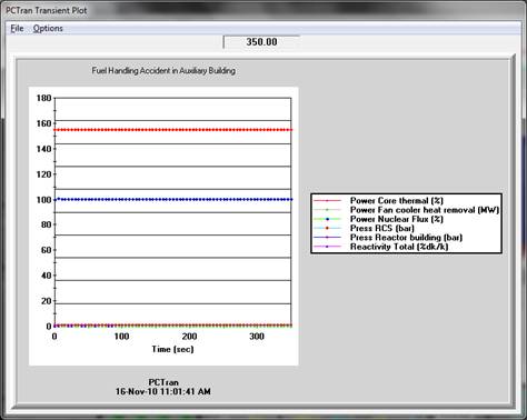
Figure 4. Fuel Handling Accident in Auxiliary Building Plot |
|
|
|
Figure 5. Turbine Trip Plot(a) |
|
|
|
Figure 6. Turbine Trip Plot (b) |

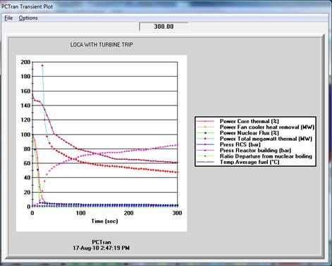
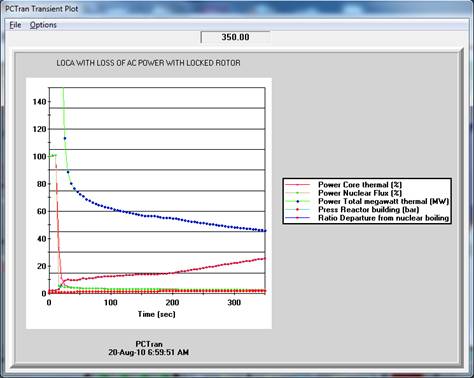


The loss of coolant accident, LOCA simulated as shown in figure1 led to a very rapid drop in coolant pressure within the system and upon reaching the operational limit; it triggered the Reactor Protection System (RPS) thereby causing a shutdown of the reactor as depicted by the thermal power and nuclear flux. This rapid drop in coolant pressure is also seen to bring about a departure from nucleate boiling. The LOCA with Inadvertent rod insertion simulation showed marked decreases in the power core thermal (%) and power nuclear flux (%) while the clad failure (%) remained constant ostensibly as a result of low neutron absorption and mechanical properties of the design clad material used. There was also great departure from nucleate boiling. The LOCA with turbine trip as depicted in figure 2 showed an astronomic decrease in the Total Power (MW) of the Plant as well as decrease in pressure from 155 bar to 61.2 bar which subsequently led to a very visible departure from nucleate boiling and this result was in consonance with the findings of [11-13] while discussing PCTRAN results for a BWR. The average fuel temperature also fell from 301°C to 276.86°C. The power core thermal (%) and power nuclear flux (%) decreased from 100% to 2.65% and 2.62% respectively. The pressure of the reactor building increased from 1.03 bar to 1.46 bar and this portends a serious safety threat to the plant. The LOCA with loss of AC power and locked rotor as shown in figure 4 depicted an increase in reactor building pressure from 1.034 bar to 2.03 bar which translated to an average increase of 0.00285 bar/sec considering the run time of 350 seconds. The total power generation of the plant also fell from 1800MW to 46.18MW, representing about 97.43% drop. The departure from nucleate boiling as seen in figure 4 is as a result of rapid drop in coolant pressure. The power core thermal (%) and power nuclear flux (%) initially increased as a result of the ramp time of 10 seconds used and subsequently decreased drastically. It should be noted that a loss of coolant accident as a result of maintenance error and a defective valve led to nuclear accident at the Three Mile Island PWR near Harrisburg, Pennsylvania in 1979. The reactor itself was shut down by its safety system when the accident began, and the emergency core cooling system began operating as required a short time into the accident. Then, however, as a result of human error, the emergency cooling system was shut off, causing severe core damage and the release of volatile fission products from the reactor vessel. Although only a small amount of radioactive gas escaped from the containment building, causing a slight rise in individual human exposure levels, the financial damage to the utility was about one billion dollars or more, and the psychological stress on the public, especially those people who lived in the area near the nuclear power plant, was in some instances severe. Hence, conditions precipitating to LOCA should be avoided.
Similar to the FHAIC, this simulation as shown in table 3 showed straight lines for power core thermal (%), fan cooler (MW), pressure (bar) and reactivity (% dk/k). What this means is that fuel handling accidents in the containment has no effect on the operations of the PWR but has severe radiological and environmental consequences. This case has no significant difference with the accident parameters with respect to time in seconds on analysis of variance. Time may not be of essence here since it is in seconds but there is significant difference in the variation of the parameters with each other. Hence, in order for accidents to be avoided in the case of loss of coolant, as source of variation, the average fuel temperature (TAF) should be most carefully considered, followed by the pressure of the coolant system (PCS), ratio of departure from nucleate boiling (RDNB), power of nuclear flux (PNF) and then the thermal power of the core (PCT) in that order.
As expected the turbine trip malfunction brought about a sharp decrease in plant power from 1800MW to 59.3MW for the 120s run time as shown in figures 5 and 6. There was no significant difference in sudden trip off of turbine with respect to time in seconds while there was significant difference in the variation of the parameters with each other. Therefore, in order to prevent sudden turbine trip off during operation, variations in the average fuel temperature (TAF) should be most carefully considered, followed by the pressure of the coolant system (PCS), ratio of departure from nucleate boiling (RDNB), power of nuclear flux (PNF) and then the thermal power of the core (PCT) in that order.
Conclusions
PCTRAN is a desirable tool for training the plant personnel on the possible sequence leading to radioactivity release. Combined with other real-time dose dispersion models, it forms an emergency response system for assurance of public safety. The results can also be used to create positive awareness for the general public especially for those in or around prospective sites such as Okaba.
Acknowledgements
Mr. Andrew Eloka-Eboka is acknowledged for assisting with statistical analysis and some level of data collection.
References
1. Lam S. K., Advanced Pressurized Water Reactor Simulator Manual, Vol. 1, 2009.
2. Lam S. K., Advanced Pressurized Water Reactor Simulator Manual, Vol. 2, 2009.
3. Höhne T., Kliem S., Bieder U., Modeling of a buoyancy driven flow experiment at the ROCOM test facility using the CFD-codes CFX-5 and TRIO U, Nuclear Engineering and Design, 2006, 236(12), p. 1309-1325.
4. Vallee C., Höhne T., Prasser H.-M., Sühmel T., Experimental investigation and CFD simulation of horizontal air/water slug flow, Kerntechnik, 2006, 71(3), p. 95-103.
5. Höhne T., Vallee C., Prasser H.-M., Experimental and numerical prediction of horizontal stratified flows, in Proceedings of the International Conference on Multiphase Flow ( ICMF ’07), Leipzig, Germany, 2007, paper no. S5 Tue C 23.
6. Krepper E., Cartland-Glover G., Grahn A., Numerical and experimental investigations for insulation particle transport phenomena in water flow, Annals of Nuclear Energy, 2008, 35, p. 1564–1579.
7. Cartland-Glover G.M., Höhne T., Kliem S., Rohde U., Weiss, F-P., Prasser H-M., Hydrodynamic phenomena in the down-comer during flow rate transients in the primary circuit of a PWR, Nuclear Engineering and Design, 2007, 237(7), p. 732-748.
8. Krepper E., Koncar B., Egorov Y., Modeling of subcooled boiling - concept, validation and application to fuel assembly design, Nuclear Engineering and Design, 2007, 237, p. 716–731.
9. Akinfaderin A., Analysis of Transient Processes in Nuclear Reactor Loops, Atomnaya Energiya, 2010, 80(5), p. 261-263.
10. Osaisai E., Diversifying the Energy Mix in Nigeria: A case for Nuclear Energy, A speech delivered at an interactive session by the Director-General of the National Atomic Energy Commission (NAEC), 2007, Available at: http://www.nigatom.org.ng/press/Diversifying%20the%20Energy%20MixA%20case%20for%20Nuclear%20Energy.Osaisai.pdf (accessed 29/04/2013)
11. Forty C.B.A., Karditsas P. J., Uses of Zirconium Alloys in Fusion Applications, EURATOM/UKAEA Fusion Association, Culham Science Centre, Available at: http://www.fusion.org.uk/techdocs/icfrm9_fortkard.pdf (accessed 01/21/2010)
12. Dufeil P., The pressurized water reactor simulator- IRSN BP 17-92262, Fontenay-aux-Roses Cedex-France, 45, p. 67, 2009.
13. Ojefua G., Oparaji O., Safety analysis of a boiling water reactor, The Thermal-Hydraulics of Water Rectors, NAEC bridging training mini project, 2009.
14. Microsimtech (online), Available at: www.microsimtech.com, (accessed 14/09/2010)