Design Criteria of Tubular Linear Induction Motors and Generators: a Prototype Realization and its Characterization
Vincenzo DI DIO1*, Giovanni CIPRIANI1, Rosario MICELI1, and Renato RIZZO2
1 DEIM Università degli Studi di Palermo, Viale delle Scienze s.n., 90128 Palermo Italy
2 DIETI Università degli Studi di Napoli Federico II via Claudio 21, 80125 Napoli Italy
E-mails: vincenzo.didio@unipa.it *; giovanni.cipriani@unipa.it ; rosario.miceli@unipa.it ; renato.rizzo@unina.it
* Corresponding author: Phone: 003909123860299; Fax: 0039091488452
Abstract
In this paper a mathematical model of tubular linear induction machines (TLIM) with hollowed induced part is recalled. Moreover the design criteria of a TLIM with hollowed iron induced part are presented as well as the technological processes to be adopted and the choice of materials to construct the various parts. The methodologies for mechanical assembling and electric wiring are considered too. A prototype with bimetallic induced part has been designed and built. Finally some experimental results on electrical and mechanical variables, when the machines are used as motors, are shown.
Keywords
Linear machines; Cylindrical coordinates; Mathematical model; Tubular induction motors; Tubular induction generators; Lamination.
Introduction
Efficient energy consumption is a key factor to Europes ambitious goals for sustainable development and activities related to air pollution and climate shifting.
In order to tackle the increasing electricity demand, a number of solutions for efficient energy consumption, generation of energy from renewable sources, and new power distribution business models for active energy control have been considered and some of them have been even pushed via regulations in national and European level.
Since photovoltaic (PV) installed power increases all over the world, solar technology is now strongly present in the electricity market, and it cannot be seen only as a vision of the future. As solar energy is one of the most abundant free sources in nature, the generation of electrical energy, compared with other counterparts, is effectively convenient, in particular in countries of the Mediterranean area, for the greater part of the year. PV generation systems are actually available in different power sizes covering the range from domestic applications to large power generation plants [1-6].
Many different improvements have been proposed and experimented to enhance efficiency not only in energy conversion (PV fields) but also in energy management (power converters). In recent times, multi-level inverters such as H bridge multi-cell cascaded inverter, Neutral Point Clamped (NPC) and Active Point Clamped (APC) have also been used for a more efficient and effective PV power conversion. Many inverter topologies have been patented, within the market development, to solve some common problems of the PV plants such as leakage currents due to parasitic capacitance of the panel and efficiency losses due to the transfer of reactive energy between the grid filters and the DC bus capacitor. Moreover, some particular topologies have been conceived for the fault tolerant operation of PV plants [7-9].
In renewable energy sources state of the art an important role is now played from sea electric energies generators [10-11], one of the most interesting is the direct generation with a tubular linear generator.
In this paper the design of a tubular linear induction machine is presented because from this theory the dual generator machines can be in a simple way developed [12-13].
In tubular linear machine the magnetic flux flows, from pole to pole, along the direction of the motion, crossing the air-gap in radial direction [14-15]. The cross-section of a tubular machine is not always circular, but can have the shape of regular polygon (square, hexagon, etc.) [16-17].
The most used configurations are those in which the cross-section is square or circular; in this case the machine is called cylindrical. The most used structure has a short inductor which is fixed to a basement, while, the induced part, usually longer than the inductor, is the moving one.
The lamination of the inductor can be either longitudinal or transversal with respect to the direction of motion. In case of transversal lamination the magnetic core of the inductor is composed of one block in which each sheet has a crown shape or of more blocks in which each sheet has the shape of a crown sector. The main disadvantage of longitudinal lamination is the difficulty to align the sheets of each core with precision, because of their length. The main disadvantage of transversal lamination is the thickness between the sheets which increases the reluctance of the magnetic circuit [18].
The aim of this research was focused on a 3-phase machine with circular cross-section, with short inductor fixed to a basement whose core (one block) has a transversal lamination and a hollowed long induced part, as a moving part.
The Mathematical Model and the Design Criteria of TLIM's
In this section, a mathematical model in cylindrical coordinates of a TLIM (used as motors) with a hollowed induced part depending on electrical, magnetic and geometrical parameters in cylindrical coordinates (just suggested by the geometry of the tubular motor) is recalled. Such construction criteria of the induced part is much more preferred in comparison to those with full induced part, considering that the contribution to the thrust due to the elementary volume of the induced part has large values in the part of the cylinder close to the external surface [18-20]. The scheme of an indefinitely long tubular linear induction motor with go air-gap, re and ri respectively outer and inner radius of induced part is represented in figure 1.
|
|
|
Figure 1. Schematic outline of an indefinitely long TLIM |
Some simplifying hypotheses have been made in expanding the mathematical model: at first, the magnetic field is assumed radial and uniform along all the air-gap, then, the magnetic saturation of the inductor and the iron cores of the induced part has been neglected, finally the inductor is thought as being a cylindrical sheet so that it is possible to obtain a sinusoidal magnetic field waveform along the air-gap [18].
The mathematical model considers the generalised form of the Ohm's equation, the Maxwell's equations and the definition of the vector magnetic potential (because the magnetic field is solenoidal), obtaining the following vector set of equations:
|
|
(1) |
|
|
(2) |
|
|
(3) |
|
|
(4) |
where Á = surface density current, s = electric conductivity, E = electric field, V = linear velocity, B = magnetic induction, H = intensity of magnetic field, A = vectorial magnetic potential.
Hence the equation of distribution of the vector magnetic potential is obtained:
|
|
(5) |
where µ = absolute permeability.
From this last equation, the cylindrical symmetry of the tubular motor suggests the following solving vector function:
|
|
(6) |
where r, z, φ = the variables of a cylindrical coordinate system and k is the propagation coefficient of the synchronous wave defined starting from the electric pulsation:
|
|
(7) |
where ω = synchronous wave defined starting from the electric pulsation, Vs = the synchronous linear velocity.
Then the vector differential equation of distribution of the vector magnetic potential is obtained:
|
|
(8) |
where j = imaginary unit,
|
|
(9) |
where s = motor slip.
The solving vector function is:
|
|
(10) |
where I and K are modified Bessel function respectively of first and second kind.
The constants C1 and C2 can be determined using the above hypotheses and recalling the properties of conservation of the vector magnetic field at the surface of separation between two media with different permeability.
Bearing in mind the Maxwell's equations, the final expression of the magnetic induction vector is as follows:
|
|
(11) |

The thrust developed by a tubular motor is determined from the electromagnetic force per unit volume of the induced part, fe, as defined by the formula:
|
|
(12) |
where ![]() = the complex
conjugate of the radial component of the magnetic induction in the induced part
of the machines.
= the complex
conjugate of the radial component of the magnetic induction in the induced part
of the machines.
This, after some mathematical simplifications, can be simplified to the following expression:
|
|
(13) |

The integral of this force per unit volume between the inner and the outer volume provides the thrust developed by the motor:
|
|
(14) |

where l = the length of the machine.
After other simplifications, the final expression of the thrust, T, is obtained [18]:
|
|
(15) |
where d = the induced sheet thickness.
From eq. (15), the design criteria, which are shown in the following, have been developed.
After choosing the synchronous speed of the motor to be designed on the basis of the specific application, after fixing the air-gap flux density to a maximum value that is typical for linear electric machines, after fixing the supply frequency, a set of curves (figure 2), which gives the thrust divided by the length of the inductor vs. the external radius of the induced part, is obtained. Figure 2 refers to the prototype described in the following paragraph.
|
|
|
Figure 2. Thrust in p.u. vs. external radius (parameter: slip) Vs=8 m/s, BM=0,4 Wb/m2, f=50Hz |
The thrust and the speed of the motor, as well as the kind of supply (1-phase or 3-phase) and the value of the voltage, are fixed taking into account the application and the mechanical performance required to the machine and also taking into account the voltage level at the place where the machine has to work. The number of pole pairs is then fixed; thus, after knowing the rated frequency, f, and the synchronous speed, the pole pitch and the length of the machine are chosen on the basis of the following formulae:
|
|
(16) |
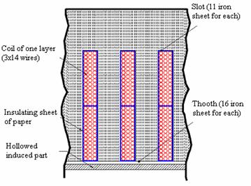
Thus, after fixing the length of the inductor, the external radius of the hollow irony induced part is derived from the set of curves in figure 2. After knowing the external radius of the irony induced part, after fixing the thickness of the air-gap between the stator teeth and the translator, the internal radius of the inductor is fixed. The air-gap is chosen as little as possible taking into account the constructive tolerances of the moving parts. The kind of mechanical working, exploiting which it is possible to obtain the best precision, is the shearing under pressure by stamp. In case of construction of only one prototype, the stamp could be too expensive. In this case laser cutting can be used or, in order to reduce the global cost at the expenses of a product of worse quality, numerically controlled machines can be used too. For the construction of the iron part of the stator core some sheets, cut differently as shown in figure 3, can be used. Figure 3 refers to the built prototype. By alternating one kind of sheets with the other, it is possible to obtain a pack in which there is a succession of teeth and slots.
|
|
|
Figure 3. Sheets of the iron core |
The thickness both of the teeth and the slots is due to the thickness of the sheets and to the number of sheets of the same kind. The holes in the sheets permit the tightening of the sheets themselves. In each hole a cut, which permits the terminals of the wiring in the slots of the core to come out, is made.
The adopted lamination is better than the other, even if it causes an increase of the thickness of the air-gap, because it permits a better assembling of the sheets.
The mentioned structure of the inductor, however, is worse from the point of view of the produced heat for Joule effect in the induced part because of the circulating currents. This aspect is not so important from the point of view of the behaviour of the motor as TLIM's usually work with discontinuous or alternative cycles. The turns of the inductor have a circular shape. They can be constructed as 1-layer or 2-layer windings. In case of a 2-layer winding two concentric winding parts can be placed in each slot of the inductor. To design the cross-section of the copper conductor of the winding, the mechanical power produced by the motor is computed, then the input apparent power is computed, after having given typical values to the efficiency and to the power-factor; finally the rated current is computed. For the insulation of the different turns composing the winding, an external cover of enamel is sufficient (double or triple layer). To determine the number of turns of each winding, the scheme of the magnetic circuit of the machine shown in figure 4 is considered.
|
|
|
Figure 4. Core schematic outline of a TLIM |
The dimensions of the radial paths of the magnetic circuit depend on the depth of the slot, and therefore on the dimension of the winding to be successively determined. Therefore one possible dimension of the depth of the slot and of the iron radial paths is fixed, after verifying the proper positioning of the winding. After fixing the length Lf of the iron path of the magnetic circuit, after taking into account the air-gap go, the f.m.m. of the translating magnetic field is computed on the basis of the following formula:
|
|
(17) |
From the f.m.m. of the translating magnetic field, after knowing the current absorbed by the motor, the number of turns for each pole pair is computed. Considering the number of slots available in each pole and the number of turns which will be allocated in each slot, the number of turns for each winding is computed. In order to build the insulation between each turn and the magnetic core and among each turn in each slot, some sheet spacers can be built and properly allocated so as to cover the surfaces of the slots; other spacers can be allocated among the windings (Figure 5 which refers to the built prototype). After knowing the diameter of each conductor of the turn and the thickness of the spacers, the depth and the width of the slots are computed.
|
|
|
Figure 5. Constructive detail of the inductor |
In particular the slot must have a width bigger than the sum of the dimensions of the number of conductors, horizontally placed, and of the dimensions of the two spacers. The slot is built placing one after the other some sheets of type a in figure 3; therefore the width of the slot is an integer multiple of the thickness of the sheets. The depth of the slot must be designed so as to allocate one or some turns and the spacers. The depth of the slot determines also the difference between the internal radius of the sheets of a and b type (figure 3). The computed depth of the slot must be coherent with the initial hypothesis on the dimensions of the radial iron path of the magnetic circuit. Subsequent trials permit to achieve good results. After knowing the length of the machine and fixing the minimum width of the slot and the number of slots, the thickness of the teeth is computed. They will be built laying, one after the other, some sheets of b type (figure 3). The end of the turns can be connected with one another by using, for the allocation of the connection, the cuts present in the core. The ends can be drawn out the core of the inductor and connected with a connection board made up of insulating material. This solution, even if it is not so good from the industrial application standpoint, permits the easy modification of the typology of the winding so as to be very suitable from the point of view of experimental applications [19,21-24]. In particular it is possible to build both 1-phase and 3-phase windings either with one layer or two layers.
Design and Construction of a TLIM Prototype with hollowed Induced Part
The prototype of the designed TLIM is 3-phase machine with rated voltage and frequency respectively of Vn = 400V and fn = 50Hz. After choosing a synchronous speed of Vs = 8m/s, assuming a thickness of the induced part of d = 2mm, fixing an air-gap flux density equal to BM = 0.4Wb/m2, assuming a conductivity of the iron of the induced part of σ = 0.15·µ·Ω/m and a iron relative permeability equal to µ = 1000, the set of curves of figure 2 is derived from (15). For the design of the motor, whose translator must have a short movement with alternative cycles, an equivalent working condition in steady-state can be considered even if with a large slip. The hypothesis is then that a motor has to be designed to be able to give a thrust T = 150N with a speed V = 2m/s. The mechanical power developed in this condition is P = 300W. If a 2 pole-pair machine must be built (p=2) the pole pitch and the length of the machine are determined on the basis of the following relationships:
|
|
(18) |
|
|
(19) |
The thrust divided by the length of the inductor is then computed (which is more or less 470N/m) and from figure 2 (characteristic with s=0.75) it can be deduced that the external radius of the inductor must be bigger than 0.04 m. After fixing the air-gap between the stator teeth and the translator to 0.8 mm, the internal radius of the inductor is then computed equal to 8.16 cm. Sheets of both shapes in figure 3 have been used. The obtained lamination is then transversal with respect to the direction of the motion. Laying one block of sheets of a type after another of the other type, the global stator core is obtained in which there is a succession of teeth and slots. The circular turns are placed in the slots and the connections can be made outside the stator core. The apparent reference power is:
|
|
(20) |
Thus the reference current is:
|
|
(21) |
with an efficiency of 0.7 and a power factor of 0.55. The conductor, chosen on the basis of the thermal criteria and consequently on the basis of the computed current value, has a cross-section of S = 1mm2 and it creates a concentric winding with 2 layers. The turns are allocated in the 24 slots of the inductor. The number of slots for pole and phase is then two. The insulation among the turns of the winding is then guaranteed by triple layer enamel. The conductor in itself has a diameter of 1.128mm; after having applied the triple layer insulation the diameter is then 1.3mm. To determine the number of turns of each part of winding, the fact the magnetic circuit has two paths in air and four paths in iron (two longitudinal and two radial) is considered. The two longitudinal iron paths are equal to the pole pitch (figure 4). A trial-and-error method is then used under the hypothesis that the radial paths have half the length of the longitudinal paths.
If If is the length of the iron path of the magnetic circuit then:
|
|
(22) |
on the basis of equation (17) the f.m.m. is then computed corresponding to the translating magnetic field:
|
|
(23) |
This value, considered the absorbed current, permits to compute the number of turns for each pole pair which is then 326. As two slots for each pole are available and two different parts winding are allocated in each slot, the number of turns for each part of winding is 40,75, then approximated to 42. 14 layers of 3 turns each are then posed as shown in figure 5. In particular the slot has a width (lslot) bigger than the sum of the dimensions of the conductors together (the diameter of each one is Dc) and of the spacers (the thickness of which is Sd); then it can be written:
|
|
(24) |
The slot is built placing one after the other some sheets of the type (figure 3) each 0.5mm thick; thus the width of the slot is an integer multiple of 0.5. In the end the slot is built laying 11 sheets of the type which guarantee a width of 5.5 mm (figure 5). The slot depth pslot is computed so that two windings and the spacers can be allocated; thus it can be written:
|
|
(25) |
In the end the depth of the slot, which is due to the difference between the internal radius of the a and b type, is about 4 cm (figure 3). This datum is coherent with the initial hypothesis on the dimension of the radial iron path of the magnetic circuit. If the sheet a of figure 3 has a depth of the crown of 3 cm, needed for the robust shutting of the core, its external radius is about 19.2 cm.
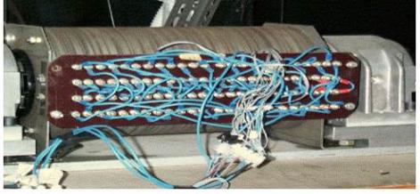
As the length of the machine is about 0.32 m, the minimum width of slot is 5.5 mm, the teeth have a thickness of 8 mm and they will be built laying one after the other 16 sheets of the b type (figure 5). The terminals of the 48 parts of winding have been drawn out of the core of the inductor and connected to an insulating basement. Figure 6 shows the scheme of the basement and the electrical connections whilst figure 7 is its photograph. A 3-phase 2-layer winding with the pitch reduced of 5/6 has been built.
|
|
|
Figure 6. Schematic outline of the basement and the electrical connections |
|
|
|
Figure 7. The basement and the electrical connections |
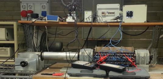
Finally figure 8 shows the prototype of the TLIM built on the basis of the design here fully explained.
|
|
|
Figure 8. The prototype of TLIM |
Experimental Measure on the Prototype
In the following the author exposes the experimental data supplied by the prototype and useful for the characterization. The procedures to measure electrical and mechanical data are also explained [25-27].
Experimental Measure of the Electrical Characteristics of the TLIM
The measure of electric data, useful for characterising the motor, has been carried out with locked and running translator. With the aid of a net analyser and three LEM's, separately for the three phases of the motor, in the conditions of locked translator: the voltages, the absorbed active power and currents, and the power factor have been measured. The analyser has, besides, provided the average values and the absorbed 3-phase active power. The values of measured electric data are shown in Table 1.
Table 1. Values of measured electric data in the conditions of locked translator
|
|
Voltage [V] |
Current [A] |
Power factor |
Power [W] |
|
|
V1=224,5 |
8,048 |
0,569 |
1028 |
|
|
V2=221,8 |
7,690 |
0,577 |
985,4 |
|
|
V3=224,5 |
7,881 |
0,554 |
980,6 |
|
Average value |
- |
7,873 |
0,554 |
- |
|
The absorbed 3-phase active power is 2994 W |
||||
With the aid of the LEM, in the conditions of running translator, the current absorbed from each phase of the motor, have been measured. Figure 9 shows the currents diagram when the motor rums with no power loading. Figure 10 shows a zoom of the same diagram of figure 9 in the range zero to 200 ms.
|
|
|
Figure 9. Absorbed currents vs. time |
|
|
|
Figure 10. Absorbed currents vs. time (in the first transient) |
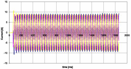
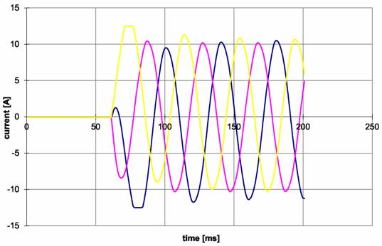
From both the diagrams we can notice that initially the currents have values more elevated than in the following. Subsequently such values increase in correspondence to a value of abscissa equal to 1600 ms, time in which the translator has finished to run. Now the motor is in the condition of locked translator; this explains the increase of the values of the currents that persists till the currents die out.
Experimental Measure of the Mechanical Characteristics of the TLIM
In order to carry out the measures of the mechanical characteristics of the motor, a mechanical system, which permits to load the motor with different calibrated weights, has been built. A hook has been joined at the end of the translator of the motor to connect a steel rope that, through a pulley, sustains the weights. An encoder able to acquire the rotational speed and send the signal to the computing board, on the shaft of the pulley, has been mounted. The illustrated system is represented in figure 11.
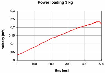
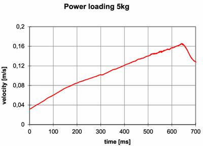
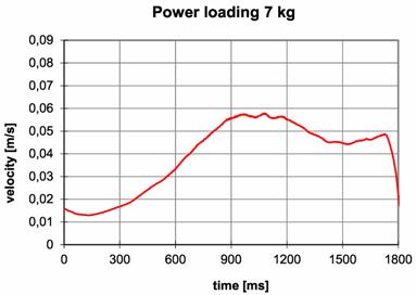
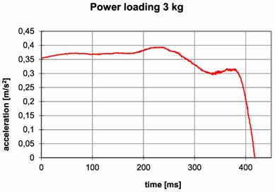
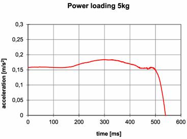
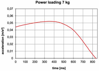
The measured mechanical data are the speed and the acceleration of the translator. Figures 12-14 show the speed vs. time after having loaded mechanically the motor with weights of values equal respectively to 3, 5 and 7 kg. Figures 15-17 show the acceleration vs. time after having loaded mechanically the motor with weights of values equal respectively to 3, 5 and 7 kg.
|
|
|
Figure 11. Scheme of the linking system of the load |
|
|
|
Figure 12. Velocity vs. time (3 kg) |
|
|
|
Figure 13. Velocity vs. time (5 kg) |
|
|
|
Figure 14. Velocity vs. time (7 kg) |
|
|
|
Figure 15. Acceleration vs. time (3 kg) |
|
|
|
Figure 16. Acceleration vs. time (5 kg) |
|
|
|
Figure 17. Acceleration vs. time (7 kg) |
Another investigation, on the prototype of TLIM, has focused on determining the start-up thrust. So the motor has been submitted to a number of starting tests with increasing load forces. The experimental results permits to estimate a start-up thrust of 115 N (maximum load at which the motor is still able to start).
Conclusions
This paper, after describing some useful tools for designing hollowed tubular linear induction machines, recalls a particularly suitable mathematical model: moreover an experimental prototype has been built and tested. By the study of the experimental curves it can be deduced that tubular linear induction motors with hollowed induced part produce a high start-up thrust and an excellent mechanical characteristic more or less linear in the first part and then decreasing. This kind of characteristics makes them particularly suitable for such industrial applications as press, solenoid valves, robot linear axles, electric switches, alternative compressors, liquid metal pumps, and hammers.
Acknowledgements
Paper supported by the contribution of SDES (Sustainable Development and Energy Savings) Laboratory at University of Palermo - D.E.I.M. department.
References
1. Di Dio V., La Cascia D., Miceli R., Rando C., A mathematical model to determine the electrical energy production in photovoltaic fields under mismatch effect, International Conference on Clean Electrical Power, 2009, p. 46-51, Doi: 10.1109/ICCEP.2009.5212083.
2. Di Tommaso A.O., Genduso F., Miceli R., Analytical Investigation and Control System Set-up of Medium Scale PV Plants for Power Flow Management, Energies, 2012, 5, p. 4399-4416, Doi: 10.3390/en5114399.
3. Di Dio V., Favuzza S., La Cascia D., Miceli R., Economical Incentives and Systems of Certification for the Production of Electrical Energy from Renewable Energy Resources, International Conference on Clean Electrical Power ICCEP 07, 2007, p. 277-282, Doi: 10.1109/ICCEP.2007.384223.
4. Di Dio V., Miceli R., Rando C., Zizzo G., Dynamics photovoltaic generators: Technical aspects and economical valuation, International Symposium on Power Electronics Electrical Drives Automation and Motion (SPEEDAM 2010), 2010, p. 635-640, Doi: 10.1109/SPEEDAM.2010.5542261.
5. Candela R., Di Dio V., Riva Sanseverino E., Romano P., Reconfiguration Techniques of Partial Shaded PV Systems for the Maximization of Electrical Energy Production, International Conference on Clean Electrical Power ICCEP 07, 2007, p. 716-719, Doi: 10.1109/ICCEP.2007.384290.
6. Di Dio V., La Cascia D., Rando C., Ricco Galluzzo G., A new control system prototype for the energy production maximization of a unequally irradiated PV system, International Conference & Exhibition on Ecological Vehicles and Renewable Energies (EVER), 2011.
7. Di Tommaso A.O., Genduso F., Miceli R., A geometrical simple approach for power silicon devices fault detection and fault-tolerant operation of a voltage source inverter, XXth International Conference on Electrical Machines ICEM, 2012, p. 1526-1532, Doi: 10.1109/ICElMach.2012.6350081.
8. Cecati C., Genduso F., Miceli R., Ricco Galluzzo G., A suitable control technique for fault-tolerant converters in Distributed Generation, International Symposium on Industrial Electronics (ISIE), 2011, p. 107-112, Doi: 10.1109/ISIE.2011.5984141.
9. Genduso F., Miceli R., A general mathematical model for non-redundant fault-tolerant inverters, International Electric Machines Drives Conference (IEMDC), 2011, p. 705-710, Doi: 10.1109/IEMDC.2011.5994897.
10. Di Dio V., Miceli R., Trapanese M., The use of sea waves for generation of electrical energy: a linear tubular asynchronous electrical generator, in OCEANS 2007, 2007, p. 1-4, Doi: 10.1109/OCEANS.2007.4449423.
11. Di Dio V., Franzitta V., Muzio F., Scaccianoce G., Trapanese M., The use of sea waves for generation of electrical energy and Hydrogen, in OCEANS 2009, MTS/IEEE Biloxi - Marine Technology for Our Future: Global and Local Challenges, p. 1-4.
12. Gieras J.F., Linear induction drives, Clarendon Press, 1994.
13. Laithwaite E.R., Linear electric machines- A personal view, Proceedings of the IEEE, 1975, 63, p. 250-290.
14. Eastham J.F., Alwash J.H., Transverse-flux tubular motors, Electrical Engineers, Proceedings of the Institution of, 1972, 119(12), p. 1709-1718.
15. Laithwaite E.R., Eastham J.F., Bolton H.R., Fellows T.G., Linear motors with transverse flux, Electrical Engineers, Proceedings of the Institution of, 1971, 118, p. 1761-1767.
16. Onuki T., Yamamura T., Sekine H., Tubular Linear Induction Motor with Square Section, in The Proceeding of International Conference on Electrical Machines Part l, 1986, p. 293-296.
17. Cox T., Development of novel linear drive machines, University of Bath, 2009.
18. Di Dio V., Montana M., State of art of tubular linear induction motor, 8th Mediterranean Electrotechnical Conference MELECON 96, 1996, 1, p. 285-288, Doi: 10.1109/MELCON.1996.551541.
19. Musolino A., Rizzo R., Tripodi E., Analysis and design criteria of a tubular linear induction motor for a possible use in the electro-magnetic aircraft launch system, 16th Symposium on Electromagnetic Launch Technology (EML), 2012, p. 1-6.
20. Musolino A., Rizzo R., Tripodi E., Tubular linear induction machine as a fast actuator: Analysis and design criteria, Progress In Electromagnetics Research, 2012, 132, p. 603-619.
21. Tsai C.-C., Hu S.-M., Chang C.-K., Vertical linear motion system driven by a tubular linear induction motor, International Conference on Mechatronics ICM 05, 2005, p. 162-167.
22. Morizane T., Masada E., Study on the feasibility of application of linear induction motor for vertical movement, IEEE Transactions on Magnetics, 1993, 29(6), p. 2938-2940.
23. Laithwaite E.R., Tipping D., Hesmondhalgh D.E., The application of linear induction motors to conveyors, Proceedings of the IEE - Part A: Power Engineering, 1960, 107(33), p. 284-294.
24. Plodpradista W., Small-scale tubular linear induction motor for pneumatic capsule pipeline system, International Conference on Electrical Machines and Systems ICEMS, 2007, p. 1528-1532.
25. Esposito N., Musolino A., Tellini B., Di Dio V., Montana M., Field Analysis in a Prototype of a Tubular Induction Machine, International Symposium on Theoretical Electrical Engineering, 1997, 1, p. 88.
26. Cardoso J.R., Cecconi V., Chabu I.E., Di Dio V., Lebensztajn L., Messina S., Nabeta S., Silva V., An integrated numerical/theoretical/experimental analysis of tubular induction motors, COMPUMAG 97 Conference On The Computation Of Electromagnetic Fields, 1997.
27. Bucci G., Landi C., Nuccio S., Ricco Galluzzo G., The on-field application of a measurement test set for the characterization of electrical drives for linear motion, Instrumentation and Measurement Technology Conference IMTC/94, Advanced Technologies in I amp; M., 1994 IEEE, 1994, 2, p. 597-600.