Effect of Manganese on the Mechanical Properties of Welded As-Cast Aluminium Joint
Isiaka Oluwole OLADELE1, Oluyemi Ojo DARAMOLA1*, and Babafemi Raphael ROGBITAN1
1 Metallurgical and Materials Engineering Department, Federal University of Technology, PMB 704, Akure, Ondo State, Nigeria.
E-mails: wolesucess2000@yahoo.com; ojaythompsoms@yahoo.com*; bamikale@yahoo.com
* Corresponding author: Phone: +2348034677039
Abstract
The effects of manganese on the mechanical properties of welded and un-weld as-cast 6063 aluminium alloy has been studied. Alloys of varying percentage of manganese from 0.019 to 0.24 were sand cast. A wooden pattern of dimensions 200×100×100mm was used, the aluminium (500g) was charged into an induction furnace and heated to 750°C for 15 minutes, this was followed by the addition of weighed powdered manganese, stirred and heated at the same temperature for another 5 minutes and thereafter poured into the already prepared sand mould at a temperature of 690°C. The as-cast aluminium samples, were sectioned into two equal parts of 45mm each using power hack saw; a weld groove was created between the sides of the samples using an electric hand grinding machine, the groove served as the path along which the filler metal was deposited on the aluminium, a single v butt joint was produced from each sample and Metal Inert Gas Welding process was carried out to produce the required joint design. The different cast samples were machined to the different test pieces after which they were assessed to determine their mechanical properties (impact, hardness (welded joint and heat affected zone) and tensile tests). The microstructures of the welded samples were also studied. From the results, it was observed that Sample F, which has 0.172% Mn, has the best hardness and impact strength while sample C with 0.160% Mn has the highest ultimate tensile strength.
Keywords
Manganese; Aluminium; Microstructures; Mechanical properties; Alloys; Filler metal; Groove; Induction furnace; Metal Inert Gas Welding.
Introduction
Aluminium alloys in which the principal alloying ingredients are: manganese, magnesium, chromium, magnesium or silicon, show little attack in corrosive environments. On the other hand, those alloys in which substantial percentages of copper are used are more susceptible to corrosive action. The total percentage of alloying elements is seldom more than 6 or 7 percent in the wrought aluminium alloys [1].
Aluminium and its alloys are part of the major engineering materials that are indispensable for now. The reasons for this are many but some of them are due to its light weight and corrosion resistance among other properties [2]. As a result of its wide areas of applications, aluminium and its alloy keep on attracting different areas of research. The need to improve its properties as well as prevent failure of the materials most especially during service is of great priority.
Aluminium alloys are more frequently welded than any other types of nonferrous alloys because of their widespread applications and fairly good weld ability. In general, higher strength aluminium alloys are more susceptible to hot cracking in the fusion zone and the Partially Melted Zone (PMZ) and losses of strength/ductility in the Heat Affected Zone (HAZ) [3]. Wrought aluminium alloy is the term used for the alloy that is suitable for shaping by a working process such as forging, rolling and extrusion. Al-Mg-Si alloy is a typical example of wrought aluminium alloy widely used for structural applications with medium strength [4-5].
The weld ability of aluminium alloys varies significantly, depending on the chemical composition of the alloy used, these alloys are susceptible to hot cracking and to combat the problem, welders increase the welding speed to lower the heat input.
The alloy of aluminium and copper are difficult to weld because of the high thermal conductivity, high thermal expansion and a tendency to give porous welds [6]. The high thermal conductivity means that there is a high rate of cooling and so there is difficulty in heating up the parent metal round the weld zone to a high enough temperature to give complete fusion with the weld pool. The high coefficient of expansion means that significant residual stresses are produced as a result of the weld area expansion being constrained by the colder surrounding parent metal. Porosity arises because the metal in the molten state absorbs hydrogen from the sources as the welding flame, fluxes and atmospheric moisture and when the weld cools, this hydrogen is released [5].
The weld ability of aluminium alloys varies significantly depending on the chemical composition of the alloy used. Aluminium alloys are susceptible to hot cracking, and to combat the problem, welders increase the welding speed to lower the heat input [7].
Aluminium alloys are readily available in various product forms. To establish a proper welding procedure, it is necessary to know the material properties of the aluminium alloy being welded. The 6xxx series alloys contain silicon and magnesium approximately in the proportions required for formation of magnesium silicide (Mg2Si), thus making them heat treatable. It has good formability, weld ability, machine ability and relatively good corrosion resistance, with medium strength [8-9].
Metal inert gas welding is the most economic process for metal thicker than 6 mm diameter. Control of penetration is difficult for thin gauge material. In the metal inert gas process a direct current (D.C.) arc of reverse polarity is struck between the work piece and a continuously fed aluminium wire which acts as both the filler and the electrode. Fluxes are unnecessary. The arc itself cleans the electrode and welds pool, whilst re-oxidation is prevented by a shield of inert gas which envelopes the area. Since the electrode is continuous, welding speeds are high with small arc size. Owing to the higher average rate at which welds can be completed, it is well suitable for the welding of aluminium [10].
In arc welding, the length of the arc is directly related to the voltage, and the amount of heat input is related to the current [11].
The aim of this research was focus on the variation effect of welding current and welding voltage on the mechanical properties of wrought (6063) aluminium alloy. The results from the research are to guide on the possibility of welding fractured wrought (6063) aluminium alloy in service and during fabrication.
Material and Method
The materials used for this research work for the production of Al-Fe-Si-Mn (0.2%), Al-Fe-Si-Mn (0.15Mn), Al-Fe-Si-Mn (0.16Mn) and Al-Fe-Si-Mn (0.17Mn) alloy systems includes high purity aluminium, ferroalloys (FeSi and FeMn), etchants, silica sand, betonies, moulding boxes.
The following equipment were used: muffle electrical resistance furnace, polishing machine, metallurgical microscope, and digital weighing balance, ram, cope, drag, cutter, brush, metallurgical microscope, hardness testing machine, impact testing machine, tensiometer, grinding machine, Arowig (GW 200) welding machine, Argon gas, Welding Goggles, Hand gloves, welding jacket.
Casting of Samples
Five different samples were produced with varying manganese percentage (3g, 6g, 9g, 12g and 15g) while one control sample was also produced. Six different moulds where produced, using a rectangular wooden pattern of dimensions 200×100×100mm.
The melting of the materials was carried out in the induction furnace. The aluminium (500g) was charged and heated for about 15minutes. This was followed by the addition of weighed powdered manganese, stirred and heated for another 5 minutes before it was poured into the already prepared sand mould. The melting temperature was 750°C and it was poured at 690°C. The melts for the six different alloys were poured into the rectangular sand moulds, allowed to cool and solidify for about 25minutes inside the mould before they were removed. The chemical composition of the as-cast samples produced is shown in table 1.
Table 1. Chemical Composition of the As Cast Samples Produced (Wt.%)
|
Samples |
Al |
Si |
Fe |
Mn |
Mg |
Zn |
Cr |
Ni |
Cu |
|
A |
98.9 |
0.170 |
0.670 |
0.170 |
0.0016 |
0.0100 |
0.0049 |
0.0066 |
0.034 |
|
B |
99.3 |
0.080 |
0.402 |
0.150 |
0.0006 |
0.0028 |
0.0044 |
0.0017 |
0.021 |
|
C |
99.0 |
0.119 |
0.610 |
0.160 |
0.0011 |
0.0059 |
0.0031 |
0.0036 |
0.028 |
|
D |
99.0 |
0.118 |
0.510 |
0.214 |
0.0007 |
0.0470 |
0.0038 |
0.0032 |
0.028 |
|
E (control) |
99.5 |
0.095 |
0.311 |
0.019 |
0.0014 |
0.0272 |
0.0049 |
0.0066 |
0.0073 |
|
F |
99.2 |
0.092 |
0.448 |
0.172 |
0.0008 |
0.039 |
0.0024 |
0.0028 |
0.034 |
Welding of Samples
An Arowig (GW 200) a multi-functional welding machine (used for both Arc and Argon gas welding) was used for welding the samples while the filler rod was AlMg5 type. The as-cast aluminium samples were sectioned into two equal parts of 45mm each using Power Hack Saw. A weld groove was created between the sides of the samples using an electric hand grinding machine; the filler rod was deposited on groove on the aluminium.
Mechanical Test
Impact Test. Representative Sample of as-cast aluminium specimens and welded specimens were subjected to impact test on an Izod V-Notch impact testing machine. The pendulum of the machine is allowed to swing freely through a known angle, some energy was used to break the specimen, and the energy was recorded directly on the scale attached to the machine. The impact test specimen is shown in figure 1. The samples were machined to 8mm×90mm and notched at 45º in the middle.
|
|
|
Figure 1. Welded Impact Test Specimen |

Hardness Test. The hardness of as-cast aluminium specimens and welded specimens were measured with the aid of Micro-hardness tester with load 490.30 MN and is measured in Vickers. The dwell time is 10secs.
Tensile Test. As-cast aluminium specimens and welded specimens were tested in tension to failure on the tensiometer. The initial gauge length and diameter were measured before subjecting them to tension. The yield and maximum loads were recorded directly from the resulted graph, the broken ends of each of the specimens were fitted and the final gauge length and also the smallest diameter of the local neck were measured. The reading thus obtained was used in the determination of the yield strength (y) ultimate tensile strength (u), percentage elongation (%E) and Yield Ratio (YR). The tensile specimen is shown in figure 2.
|
|
|
Figure 2. Welded Tensile Sample |
Metallographic Examination
Samples of welded aluminium and as-received specimens were mounted in hot Phenolic mounting powder and were ground on a water lubricated hand grinding set-up of abrasive papers, progressing through from the coarsest to the finest grit sizes. The 240, 320, 400 and 600 grades were used in that order. Polishing was carried out on a rotating disc of a synthetic velvet polishing cloth impregnated with micron alumna paste. Final polishing was carried out with diamond paste. The specimens were then etched with the standard 2% Nital so as to reveal the ferrite grain boundaries. The optical microscopic examinations were carried out on a metallurgical microscope at a magnification of 400X. The specimens were illuminated with 100 kilowatts detachable quartz.
Results and Discussion
Hardness is a measure of degree of indentation the surface of a material can withstand under standard test conditions. Figures 3-4 present the average hardness of the samples. It was observed that the hardness of sample F is the best with an average hardness of 705.12MPa followed by sample E with 560.96 MPa, while sample A has the least average hardness of 499.18MPa.
Impact energy is a measure of energy absorbed during the fracture of a material of a standard dimension and geometry when subjected to a sudden loading. Figure 5 presents the impact energy of the welded samples. It was observed that the impact strength of sample F was the best with average impact energy of 17.4J followed by sample A with 15.5J while sample E has the least average impact energy of 5.4J.
|
|
|
Figure 3. Variation of Average Hardness of Welded Joint against Samples |
|
|
|
Figure 4. Variation of Average Hardness of Heat Affected Zone against Samples |
|
|
|
Figure 5. Variation of Average Impact Toughness (J) against Welded Samples |
The ultimate tensile strength is the stress at the maximum applied load on the engineering stress-strain curve (maximum stress that can be sustained by a material in tension). Figure 6 shows the average ultimate tensile strength results. It was observed that sample C has the best ultimate tensile strength with 35.7Mpa/mm2, followed by sample A with 31.81Mpa/mm2 and sample E with the least ultimate tensile strength with 18.97Mpa/mm2.
|
|
|
Figure 6. Variation of Ultimate Tensile Strength(U.T.S) to Welded Samples |
The stress-strain curve is used to determine the modulus of elasticity, elastic limit, percentage elongation, proportional limit, and reduction in area, tensile strength, yield point, yield strength and other tensile properties as presented in figures 7-12.
|
|
|
Figure 7. Stress Strain Graph of Welded Sample A |
|
|
|
Figure 8. Stress Strain Graph of Welded Sample B |
|
|
|
Figure 9. Stress Strain Graph of welded joint Sample C |
|
|
|
Figure 10. Stress Strain Graph of welded joint Sample D (0.214% Mn) |
|
|
|
Figure 11. Stress Strain Graph for welded joint Sample E (Control) |
|
|
|
Figure 12. Stress Strain Graph of Welded Joint Sample F |
The microstructures obtained are shown in the figure13-18.
|
|
|
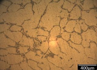
Figure 13. Microstructure of Sample A (400X) |
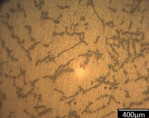
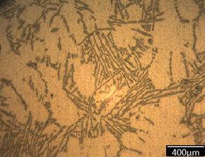
In figure 14 and 15, the micrograph of sample B and C shows moderately dispersed distribution of the aluminium magnesium (AlMg5) 5356 filler rod deposited into the aluminium matrix, and this is responsible for its low impact energy, moderate hardness, and relatively large modulus of elasticity values that was obtained.
|
|
|
Figure 14. Microstructure of Sample B (400X) |
|
|
|
Figure 15. Microstructure of Sample C (400X) |
The micrograph of samples A and C shows a uniform distribution of aluminium magnesium (AlMg5) 5356 filler rod deposited into the aluminium matrix and this is responsible for its low hardness, high impact energy, low modulus of Elasticity and moderate hardness for heat affected zone.
In figure 16, the micrograph of sample D shows high concentration and distribution of the Aluminium Magnesium (AlMg5) 5356 filler rod deposited into the joint of the aluminium matrix and this is responsible for its moderate impact energy, improved hardness, better modulus of elasticity and better hardness at the heat affected a zone value that was obtained.
|
|
|
Figure 16. Microstructure of Sample D (400X) |
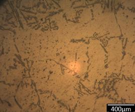
In figure 17, the micrograph of sample E shows dispersed distribution of the Aluminium Magnesium (AlMg5) 5356 filler rod deposited into the joint of the aluminium matrix and this is responsible for the low impact energy, improved hardness, high modulus of elasticity and moderate hardness at the heat affected zone values that was obtained.
|
|
|
Figure 17. Microstructure of Sample E (400X) |
|
|
|
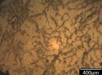
Figure 18. Microstructure of Sample F (400X) |
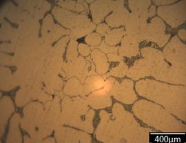
The micrograph of sample F shows dispersed distribution of the Magnesium-Aluminium (MgAl5) filler rod deposited into the joint of the aluminium matrix and this is responsible for the low impact energy, improved hardness, high modulus of elasticity and moderate hardness at the heat affected a zone value that was obtained.
Conclusions
The effect of manganese as an alloying element on welded joint of aluminium has been studied and the results showed that the mechanical properties of the aluminium alloy with the given composition improved generally within the chosen percentage of manganese being used as the alloying element. However, sample F, with 17.2%Mn has the best hardness (Welded joint and Heat Affected Zone) and impact strength while sample C, with 21.4% has the best ultimate tensile strength. It therefore implies that manganese can be added to aluminium in order to improve its mechanical properties and, hence its areas of applications.
References
1. Polmear I.J., Edward A., Light Alloys (Metallurgy of light metals), Second edition, 1993, p. 124-167.
2. Polmear I.J., Edward A., Light Alloys (Metallurgy of light metals), Third edition, 1995, p. 134-160.
3. Sindo K., Welding metallurgy, 2nd edition, New York, John Wiley & Sons, 2003.
4. Ravikumar E., Arunkumar N., Sunnapa G.S; Characterization of Mechanical Properties, Characterization of Mechanical Properties of Aluminium (AA 6061-T6) By Friction Welding, 3rd International Conference on Mechanical, Automotive and Materials Engineering (ICMAME 2013), Singapore, 2013, p. 127-131.
5. Basheer U.M, Fauzi M.N.A, Ismail A.B., Zuhailawati H., Effect of Friction Time on the Properties of Friction Welded YSZ-Alumina Composite and 6061 Aluminium Alloy, A Qatar Foundation Academic Journal, 2013, Qscience Connect 2013, Available at: http://dx.doi.org/10.5339/connect.2013 (accessed 12/04/2013).
6. Oladele I.O., Omotoyinbo J.A., Effect of Welding Current and Voltage on the Mechanical Properties of Wrought (6063) Aluminium Alloy, Material Research Journal, 2010, 13(2), p. 125-128.
7. Abdulwahab M., Studies of the Mechanical Properties of Agehardened Al-Si-Fe-Mn Alloy, Australian Journal of Basic and Applied Sciences, 2008, 2(4), p. 839-843.
8. Madugu I.A., Abdulwahab M., The Mechanical Properties of As-cast Al-Si-Fe Alloy, Nigerian Journal of Research and Production, 2007, 10; p. 72-80.
9. Honarbaklhsh R., Ghazvinloo H.R., Shadfar N., Influence of Friction Stir Welding Variables on Hardness, UTS and Yield Strength of Joints Produced in SSM Cast A356 Aluminium Alloy, Australian Journal of Basic and Applied Sciences, 2010, 4(8), p. 3010-3015.
10. Ovat F.A, Asuquo L.O., Anyandi A.J., Microstructural Effects of Electrodes Types on the Mechanical Behaviour of Welded Steel Joints, Research Journal in Engineering and Applied Sciences, 2012, 1(3) p. 171-176.
11. Anderson Jr.J.D., The Airplane: a history of its technology, Reston, American Institute of Aeronautical and Astronautics, 2002.
12. Subbaiah K., Geetha M., Grovindarajan, Rao S.R.K., Friction Stir Welded Joints of Cast Scandium Added Aluminium-Magnesium Alloy, International Journal of Advanced Engineering Technology, 2011, 2(3), p. 10-13.
13. Lancaster J.F., Metallurgy of welding, 5th edition, London, Chapman and Hall Publisher, 1994.
14. International Standards for Materials ASTM, Trends Welding Research in the United States, Ohio Materials Park, 2003.
15. Robert B.R, Metallic material specification handbook, 4th edition, Dordrecht Netherlands, Chapman and Hall, 1994.