Gating System Design for Casting thin Aluminium Alloy (Al-Si) Plates
Victor ANJO1* and Reyaz KHAN1
1 Department of Mechanical Engineering, Federal University of Technology Minna Niger, State Nigeria
E-mails: victoranjo2008@live.com*; reyazkhan1@yahoo.com
* Corresponding author: Phone: +2348057846076
Abstract
The main problems caused by improper gating are entrained aluminium oxide films, cuts and washes, low casting yield and entrapped gas. This study describes the design of a gating system to produce thin Aluminium cast alloy plates of different sizes and thicknesses of 4mm, 6mm, 8mm, and 10mm using the non-pressurized gating with ratio of 1:4:4 and green sand moulding technique. The gating design was based on the laws of fluid mechanics and empirical rules of gating for non ferrous metals. The equipments used for this experiment includes; a coal fired crucible furnace and an X-Ray machine. Materials used include; silica sand, clay, wood, glue and Aluminium alloy scraps. The experimental procedure involved: the gating design calculations, construction of wooden pattern and gating; using the wooden pattern and gating to produce the mould cavities and gating; melting, melt treatment and pouring of melt in the sand mould to produce the casting. The plate castings after removal from mould were visually examined for surface defects and after fettling and cleaning X-Ray radiography was used to find the internal soundness of the castings. From the results obtained in the experiment, it was found that there were no internal defects and quality castings were produced.
Keywords
Gating Design; Casting; Green Sand; Aluminium alloy (Al-Si); Thin plates.
Introduction
One of the critical elements that have to be considered for producing a high quality in sand casting product is the gating design. Many extensive research efforts have been made in attempts to study the effect of gating system on the flow pattern of melt entering the mould [1,2]. It has been shown that an optimum gating system design could reduce the turbulence in the melt flow; minimize air entrapment, sand inclusion, oxide film and dross [3]. The formation of various casting defects could be directly related to fluid flow phenomena involved in the stage of mould filling. For instance, vigorous streams could cause mould erosion; highly turbulent flows could result in air and inclusions entrapments; and relatively slower filling might generate cold shuts [4]. Furthermore, porosity which is a common defect in casting also could result from improper design of gating system [5]. In [6] also found out that: recently, demand for the lightweight alloy in electric/electronic housings has been greatly increased. However, among the lightweight alloys, aluminium alloy thin-walled casting is problematic because it is quite difficult to achieve sufficient fluidity and feed ability to fill the thin cavity as the wall thickness becomes less than 6 mm. During the casting process, molten aluminium alloy is poured into the pouring basin and flows through the sprue to the runners, then through the ingate (the passage trough that leads the molten metal from the gating system into the mould cavity) to the mould cavity. Molten metal’s are fluids and therefore obey the natural laws of fluid mechanics. A proper and convenient gating system is required in the production of quality castings with soundness of surface and without defects.
In the metal casting process, the proper feeding of the molten metal into the mould cavity have been very problematic especially when it involves castings with thin sections. In order to properly feed the molten metal into the mould cavities of these thin section castings, a properly design gating system is required. The problem in this study is how to design a single optimize gating system that will be use to produce for aluminium alloy plates of different sizes and also minimize defects in the castings.
The gating system, which is composed of: sprue, runners, ingates and overflows, is a series of passages trough that the molten metal flows into the mould cavity to produce the castings for minimizing degradation in metal quality and for minimizing the occurrence of shrinkage porosity in the solidifying casting differ among the various casting process, primarily as a function of process limitations [7-12] discovered that a good gating design and pattern allowances ensures proper heat flow and cooling thereby eliminating casting defects.
The aim of this research was to improve the quality of Aluminium alloy thin plates castings produced in green sand moulding process through proper gating design and Conserve materials by the recycling of aluminium alloy scraps as the charge materials.
Material and Method
The materials used for this study include: wood, glue (Alteco 110), Aluminium (Al-Si-Mn-Mg-Cu) alloy scraps, silica sand (River sand), betonies (Clay), water and additive (wood ash). The equipments include: Coal fired Crucible Melting furnace, Colchester Lathe Machine and a 300mA X-ray machine.
Gating Design Calculations
The methods that will be use for this study is the principle of gating system design calculations according to: [13-16]. For this study on aluminium alloys, we shall be using the non-pressurized gating system with a gating ratio of:
|
As:Ar:Ag=1:4:4 (Non pressurized gating ratio) |
(1) |
where As = the cross sectional area of the sprue exit, Ar = the cross sectional area of the Runner(s) and Ag = the cross sectional area of the ingate(s). The choke (the smallest cross sectional area) is at the sprue base exit therefore.
|
As=Ac |
(2) |
where Ac = the cross sectional area of the choke.
Pattern Allowances
Shrinkage allowance for Aluminium alloys is 16mm/m [13]. These allowances shall be added to the pattern parts in the mould cavity.
|
Pattern Dimension = Actual Dimension + Shrinkage allowance |
(3) |
For 4mm thickness plate, actual length = 80mm and breath = 40mm.
Pattern thickness = 4 + (0.004×16) = 4.064mm
Pattern length = 80 + (0.08×16) = 81.28mm
Pattern breath = 40 + (0.04×16) = 40.64mm
For 6mm thickness plate, actual length = 120mm and breath = 60mm;
Pattern thickness = 6 + (0.006×16) = 6.096mm
Pattern length = 120 + (0.12×16) = 121.92mm
Pattern breath = 60 + (0.06×16) = 60.96mm
For 8mm thickness plate, actual length = 160mm and breath = 80mm;
Pattern thickness = 8 + (0.008×16) = 8.128mm
Pattern length = 160 + (0.16×16) = 162.56mm
Pattern breath = 80 + (0.08×16) = 81.28mm
For 10mm thickness plate, actual length = 200mm and breath = 100mm;
Pattern thickness = 10 + (0.01×16) = 10.16mm
Pattern length = 200 + (0.2×16) = 203.2mm
Pattern breath = 100 + (0.1×16) =101.6mm
Table 1 shows the dimensions of the pattern plates used in the design of a gating for four thin Aluminium alloy plates.
Table 1. Dimensions of the pattern plates
|
Plate Designation |
Thickness (mm) |
Length (mm) |
Width (mm) |
Volume (mm3) |
|
A |
4.06 |
81.28 |
40.64 |
13411.07 |
|
B |
6.10 |
121.92 |
60.96 |
45335.68 |
|
C |
8.13 |
162.56 |
81.28 |
107420.69 |
|
D |
10.16 |
203.20 |
101.6 |
209754.42 |
Step 1: Calculate the total weight of castings
|
W = ρ×V |
(4) |
where: W = total weight of casting, ρ = density, V = total volume of casting.
V = 13411.07 + 45335.68 + 107420.69 + 209754.42 = 375921.86mm3
W = 2500×375921.86×(10-3)3 = 0.9399Kg
Step 2: Calculate the pouring rate and pouring time
Pouring rate formula for non-ferrous gating:
|
|
(5) |
where: R = pouring rate, b = constant, depends on wall thickness; typical values of b are shown on Table 2.
Table 2. Values of constant (b) for different Casting thickness [14]
|
Wall thickness (mm) |
Below 6 mm |
6-12 mm |
Above 12 mm |
|
b -constant |
0.99 |
0.87 |
0.47 |
![]()
|
|
(6) |
where: Ra = adjusted pouring rate, K = metal fluidity, C = the effect of friction with values of 0.85-0.90 for tapered sprues in the gating system.
|
|
(7) |
where: t = pouring time [14].
![]()
![]()
Step 3: Calculate the effective sprue height
Sprue height Hsprue = 100mm [15]
Height of casting in the cope H1 = 5 mm
Total height of casting H2 = 10mm, then using equation (8) from [14]:
|
|
(8) |
where: Hp = effective sprue height.
![]()
Step 4: Calculate the choke cross sectional area
The flow rate equation:
|
|
(9) |
where: Ac = choke area (mm2), W = casting weight (Kg), ρ = density of molten metal (kg/m3), Hp = effective sprue height (mm), C = discharge coefficient (0.8), g = acceleration due to gravity (9.81m/s2), Ra = adjusted pouring rate (Kg/s) and t = pouring time (s) [16].
![]()
Step 5: calculation of the sprue inlet area, since sprue exit area Asprue_exit =choke area Ac
Continuity equation:
|
|
(10) |

where Asprue_inlet = sprue inlet cross-sectional area, Asprue_exit = sprue exit cross-sectional area, Hsprue_inlet = distance between the ladle and sprue top and Hsprue_exit = distance between ladle and sprue exit.
Asprue-exit = 356.641mm2
Hsprue-inlet = 50mm
Hsprue-exit = 50 + 100 = 150mm
![]()
Radius of the sprue inlet:
![]()
Radius of the sprue exit:
![]()
Step 6: Calculation of the Ingates and Runner cross-sectional areas using a gating ratio of 1: 4: 4
Runner cross-sectional area = 4×356.641mm2 = 1426.564mm2
|
Area of a Square = L×B |
(11) |
where: L = length, B = breath. Since for a square, Length = Breath, therefore, Area = (Length) 2.
Length of Runner cross section = Breath of Runner cross section.
Length of Runner = 37.77mm and Breath of Runner = 37.77mm.
Total Ingates cross-sectional area = 4×356.641mm2 = 1426.564mm2
Since we have four plates, we shall be using four ingates. Therefore, the cross sectional area of each ingate will be calculated as follows:
Total plates thickness = 4 + 6 + 8 + 10 = 28mm for the 4mm thickness plate.
Ingate cross sectional area = (4/28)×1422.4448 = 203.21mm2
For the 6mm thickness plate:
Ingate cross sectional area = (6/28)×1422.4448 = 304.81mm2
For the 8mm thickness plate:
Ingate cross sectional area = (8/28)×1422.4448 = 406.41mm2
For the 10mm thickness plate:
Ingate cross sectional area = (10/28)×1422.4448 = 508.02mm2
Step 7: Design of Sprue well
Sprue well cross-sectional area = 5×sprue exit area = 5×356.641mm2 = 1783.21mm2
Sprue well depth = 2×runner depth = 2×37.77 = 75.54mm
Results and Discussion
After the calculations of the gating system dimensions and the pattern allowances values obtained was transfer to the wood pattern and gating in order to make the mould. The mould cavity was produced by placing the pattern in a wood frame, filling it with the green sand mix and properly ramming the sand mix with the pattern in it to give the mould strength. After the pattern was removed, the mould was assembled back together. Figure 1, shows the schematics of the mould cavities and gating produced by the wood pattern and gating. 5.6Kg Aluminium alloy scraps was charge into a crucible furnace fired with charcoal. 0.5% Hexachloroethane (C2Cl6) tablets were added to the molten metal to remove dissolve gases from the melt and soon after degassing, at a temperature of 740°C, the metal was poured into the mould. After solidification and cooling, the casting was knocked out of the mould (figure 2) and cleaned from sand particles (figure 3). The X-Ray radiograph of the castings was taken for inspection to check for internal defects in the castings (figure 4). Table 3 present the composition of melt.

Figure 1. Schematics of the Mould Cavities of Plates A,B,C & D and the Gating
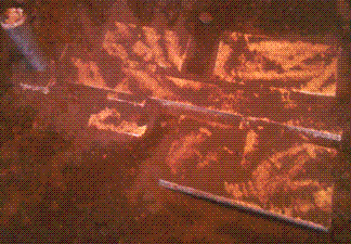
Figure 2. Removal of Casting from Mould
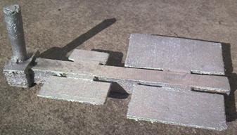
Figure 3. Casting After Cleaning
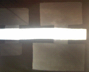
Figure 4. X-Ray Radiograph of Castings
After knocking out and cleaning, X-Ray radiograph (figure 4) and visual inspection carried out show that the castings were free from internal defect and with few surface defects. The gating design can also be employed in metallic mould to produce quality casting with better surface finish than that of green sand mould.
Table 3. Composition of Melt
|
Element |
Al |
Si |
Mn |
Mg |
Cu |
|
Composition % Weight |
96.290 |
1.523 |
0.930 |
0.822 |
0.33 |
A summary of the gating system characteristics is shown in the Table 4, showing the various dimensions of the gating system obtained in the design calculations.
Table 4. Dimensions of the Gating elements for the four plates
|
Part |
Thickness/Height (mm) |
Length (mm) |
Width (mm) |
|
Pouring Basin |
50.0 |
50.0 |
50.0 |
|
Sprue |
100.0 |
Inlet Radius = 14.0 |
Exit Radius = 10.7 |
|
Sprue well |
75.6 |
39.6 |
45.0 |
|
Runner |
300.0 |
37.8 |
37.8 |
|
Ingates |
|||
|
A |
4.0 |
50.8 |
10.0 |
|
B |
6.0 |
50.8 |
10.0 |
|
C |
8.0 |
50.8 |
10.0 |
|
D |
10.0 |
50.8 |
10.0 |
From the results obtained in this experiment, it was seen that proper gating design and proper melt treatment i.e. degassing and slug removal produced castings with few defects.
Conclusions
A horizontal gating system was designed to produce thin Aluminium alloy plates using green sand mould and a non-pressurized gating system with a gating ratio of 1: 4: 4. The horizontal gating design made use of horizontal feeders along the sides of the thin wall plates. Through this design, a low turbulence uniform filling of mould cavities was obtained. Side ingates gating systems, provides a lamina flow through the ingates to the mould cavities and minimizes air entrapment in the mould cavities. The X-ray radiograph of the four plates taken, shows that there were no internal defects in the castings. The result obtained from this experiment shows that “Gating system design in casting process is one of the crucial factors to produce good quality of casting product “ [19].
Acknowledgements
We wish to acknowledge the entire Academic and Technical staffs of the Mechanical Engineering Department, Federal University of Technology Minna Niger State, Nigeria for their support and encouragement.
References
1. Espraza C.E., Guerro M.M.P., Rios M.R.Z. Optimal design of gating systems by gradient search methods,. Computational Materials Science, 2005, p. 2-37.
2. Masoumi A., Effect of Gating Design on Mould Filling, International Journal of Cast metal Research, American Foundry Society, USA, 2007.
3. Hu B.H., Tong K.K., Niu X.P., Pinwill I., Design and optimization of runner and gating systems for the die casting of thin walled magnesium telecommunication parts through numerical simulation, Journal of Materials Processing Technology, 2002, 105, p. 128-133.
4. Attar E.H., Babaei R.P., Asgari K., Davami P., Modelling of air pressure effects in casting moulds, Journal of Modelling and Simulation in Materials Science and Engineering, 2005, 13,p. 903-917.
5. Lee P.D., Chirazi A., See D., Modelling micro porosity in Aluminium - Silicon alloys: a review, Journal of Light Metals, 2001, 1, p. 15-30.
6. Young-Chan K., Chang-Seog K., Jae-Ik C., Chang-Yeol J., Se-Weon C., Sung-Kil H., Die Casting Mould Design of the Thin-walled Aluminum Case by Computational Solidification Simulation, Journal of Material Science Technology, 2008, 24(3), p. 383-388.
7. José C.F., A study of advanced die-casting technology integrating CAD/RP/FEA for Zn castings, International Journal of Advanced Manufacturing Technology, 2006, 31, p. 235-243.
8. Zhizhong S., Henry H., Xiang C., Qigui W., Wenying Y., Gating System Design for a Magnesium Alloy Casting, Journal Material Science Technology, 2008, 24(1), p. 93-95
9. Shahmiri M., Kharrazi Y.H.K., The effects of Gating System on the soundness of lost foam casting (LFC) process of Al-Si Alloy (A.413.0), International Journal of Engineering Transactions B: Applications, 2007, 20(2), p. 157-166.
10. Twilley M., ASTM B-108 Aluminum Tensile Bar Mold Redesign, International Journal of Metal casting American Foundry Society Winter, 2012, p. 57-61.
11. Shaha S.K., Haque M.M., Simulation of Heat Flow in Computational Method and Its Verification on the Structure and Property of Gray Cast Iron, American Journal of Applied Sciences 2010, 7(6), p. 795-799.
12. Peters F., Voigt R., Ou S.Z., Beckermann C., Effect of mould expansion on pattern allowances in sand casting of steel, International Journal of Cast Metals Research, 2007, 20(5), p. 275-287.
13. Rajput R.K., Manufacturing Technology, Metal Casting, third edition, Laxmi Publications Ltd, New Delhi, India, 2007, p. 46-59.
14. Jain P.L., Principles of Foundry Technology, fourth edition, McGraw-Hill Company Limited, New Delhi, India, 2003, p. 176-184.
15. Campbell J., Castings, Linacre House, Jordan Hill, Oxford, Butterworth-Heinemann Ltd., 1991.
16. Rao P.N., Manufacturing Technology, Foundry, Forming and welding, third edition, The McGraw-Hill Company Limited, New Delhi, India, 2009, p. 128-138.
17. Mares E., Sokolowski J.H., Artificial intelligence-based control system for the analysis of metal casting properties, Journal of Achievements in Materials and Manufacturing Engineering, 2010, 40(2), p. 149-154.
18. Abolarin M.S., Olugboji O.A., Ogunwole O.A., Casting of Brake Disc and Impeller from Aluminum Scrap Using Silica Sand, Leonardo Electronic Journal of Practices and Technologies, 2007, 10, p. 145 -150.
19. Mohd Rizuan Mohammed Shafiee, Mohd Yussni Bin Hashim and Mohd Nusyakirin Bin Said, Effects of gating design on the mechanical strength of thin section castings, Malaysian Technical Universities Conference on Engineering and Technology, 2009, p. 1-4.