Drop Weight Impact Studies of Woven Fibers Reinforced Modified Polyester Composites
Muhammed Tijani ISA1*, Abdulkarim Salaw AHMED1, Benjamine Olufemi ADEREMI1, Razaina Mat TAIB2, Hazizan Md AKIL2, Ibrahim Ali MOHAMMED-DABO1
1Department of Chemical Engineering, Ahmadu Bello University, Zaria Nigeria, 810261.
2School of Materials and Mineral Resources, University of Sains Malaysia, 14300, Nibong Tebal Penang, Malaysia.
E-mails: mtisa@abu.edu.ng; asahmed2007@yahoo.com ; boaderemi@abu.edu.ng; razaina@eng.usm.my; hazizan@eng.usm.my; iroali@mail.ru
* Corresponding author: Phone: +2348034536374
Abstract
Low velocity impact tests were conducted on modified unsaturated polyester reinforced with four different woven fabrics using hand-layup method to investigate the effect of fiber type and fiber combinations. The time-load curves were analysed and scanning electron microscopy was used to observe the surface of the impacted composite laminates. The results indicated that all the composites had ductility index (DI) of above two for the test conducted at impact energy of 27J with the monolithic composite of Kevlar having the highest DI. The damage modes observed were mainly matrix cracks and fiber breakages. Hybridization of the fibers in the matrix was observed to minimize these damages.
Keywords
Hybrid; Fibers; Microstructures; Lay-up; Ductility Index; Impact.
Introduction
Fiber reinforced composites have wide range of engineering applications in areas like aerospace, automobile, defense and marine, because of their advantageous characteristics of light weight , high strength, stiffness and resistance to high temperature [1- 4]. Despite these advantages of their properties, they are still susceptible to damages caused by various factors during manufacture and in service [5]. The damage mode caused by low impact velocity loadings on composites consists of delamination, matrix cracking and fiber failure [4-5]. The damage mode in high impact velocity loading is essentially the same for low impact velocity, but with additional damage mechanisms like shear plugging [6].
Enhancement of the impact performance of composites by various methods has been shown through several researches. Fiber treatment [7], interleaving [8], hybridization of fibers [1, 3, 5, 8-13] and matrix modification [14] are prominent among the methods reported. Hybridization is the combination of two or more fibers in a matrix. Hybridization has been used by many workers because of its advantages of reducing cost by combination of cheap fibers with expensive ones and the ability to optimize composites properties [15]. It has been reported that the type of fibers used, fiber configuration and stacking sequence has effects on structural and mechanical performance of hybrid composites [8, 11, 15]. It was established that laminates with asymmetric stacking sequence outperform those with symmetric sequence [7].
In most of the reported work, two fibers were commonly hybridized in a matrix and in some cases short fibers are combined with woven fibers in the matrix. Carbon/epoxy interlayer with short Kevlar 49 fiber [5], E-glass fiber in vinylester with different coupling agent [7], aramid/polyethylene fiber in vinylester [8], polyethylene/carbon fiber in epoxy resin [12], S2 glass/ carbon fiber in epoxy resin [9], glass/polyethylene fiber in poly(methyl methacrylate) [16], wood fiber/talc in polyhydroxybutyrate -co- vatrate [17], bio/glass fiber in polyester resin [18] and short glass fiber/wollastonite in polypropylene [19] are few examples from numerous systems that have been studied. In these systems maximum of two fibers were combined in a matrix.
Considering a wide range of materials available for combinations, there is a need to investigate other system combinations and more importantly, a system with more than two woven fibers in a modified matrix.
In this study the drop weight impact response of glass, Kevlar, nylon and locally woven nylon fibers composites and their hybrids (bi and ter) in modified polyester matrix were investigated via analysis of the load-time curves and scanning electron microscopy (SEM).
Material and Method
The materials employed in this investigation were general purpose polyester resin manufactured by ADD resins and chemicals (pty) Ltd., South Africa. The glass fiber was woven roving E-glass fiber of denier 10,820, tightness of weave 7.65 cm2, manufactured by Jiaxing Sunlong Industrial and Trading Co., Ltd., China. The Kevlar 49 fiber was a plain weave mat with denier 1500, tightness of weave 46.24 cm2, manufactured by Carr Reinforcement Limited UK. The nylon fiber was plain weave with denier 1320, tightness of weave 183.40cm2, manufactured by Tar Erh, Co. LTD China. The hand woven nylon fiber had denier 2360, tightness of weave 117.81 cm2. Dicotyl phthalate (DOP) manufactured by Zhenzhou p and b Chemical Co. Ltd, China. The fiber mats were used as purchased, while the polyester resin was modified by 5 wt% dicotyl phthalate (DOP).
Production of Composite samples
5 wt% of dioctyl phthalate (DOP) [20-21] was added to General purpose polyester resin and mixed for 10 minutes, after which 2 wt% of methyl ethyl ketone was added, mixed for 3 minutes and 2 wt% cobalt accelerator was then added and mixed for another 2 minutes. Previously, a metallic mould of dimension 21x16x4 cm was cleaned and coated with release agent.
Nine layers of the glass fiber were weighed and then hand lay- up in the mould using 1 inch pure bristles brush to apply the polyester mix one after the other. The mould was covered and transferred to a Carver laboratory hydraulic press, (model M, serial number, 23505 - 208) for compression at a pressure of 1013.40 kN/m2 [22]. The mould was removed from the press after 6 h and was left to stay for another 18 h after which the content, glass fiber reinforced polyester (GFRP) was removed and post cured in the oven at 60oC for 3 h. The same procedure was adopted to produce other samples: Kevlar composite (KFRP), nylon composite (NFRP) and locally woven nylon composite (LNFRP). Asymmetric stacking sequence was used to produce hybrid of samples of Kevlar and glass composite (KGFRP), glass and nylon composite (GNFRP) and glass and local nylon composite (GLNFRP) using 5 layers of glass with 4 layers of the other fiber respectively with the same procedure as earlier described. Ter hybrid composites of the fibers were produced using asymmetric stacking sequence with 3 layers each of the fibers. Some basic features of the laminates and their compositions are presented in Table 1 and 2. Figure 1 shows sample schematic diagrams of composite laminates. Figure 1 A serves as sample for NFRP, KFRP and LNFRP, Figure 1 B serves as sample for GNFRP and GLNFRP but with the 5 layers of glass fiber on top of the 4 layers of nylon fiber and local nylon fiber respectively and Figure 1 C serves as sample for the KGLNFRP.
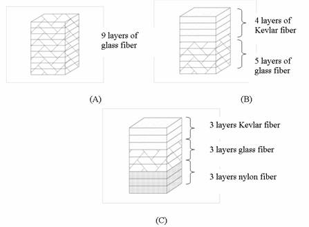
Figure 1. Sample diagrams of composite laminates: (A) laminate of 9 layers of glass fiber, (B) hybrid laminate of 4 layers of Kevlar fibers and 5 layers of glass fiber (C) ter hybrid of 3 layers each of Kevlar, glass and nylon fibers [23]
Table 1. Basic Features of Composites Laminate Used
|
Material |
Thickness (mm) |
Density (g/cm3) |
Geometry (mm x mm) |
|
GFRP |
4.5 |
1.887 |
80 x 80 |
|
KFRP |
4.0 |
1.146 |
80 x 80 |
|
NFRP |
4.0 |
1.145 |
80 x 80 |
|
LNFRP |
9.0 |
1.161 |
80 x 80 |
|
KGFRP |
4.0 |
1.518 |
80 x 80 |
|
GNFRP |
5.0 |
1.522 |
80 x 80 |
|
GLNFRP |
7.5 |
1.364 |
80 x 80 |
|
KGNFRP |
3.5 |
1.373 |
80 x 80 |
|
KGLNFRP |
7.0 |
1.200 |
80 x 80 |
Drop Weight Impact Test
The samples were cut into approximately size of 80 mm x 80 mm and one sample at a time was held on a beam with double sided tape, on the sample holder of a drop weight impact tester that was set up with sensitivity of – 4.019, fast on trigger mode, pre-time and post-time of 1000 seconds respectively. A weight of 2 kg was added to a load cell which already weighed 2.5 kg with hemi-spherical impactor of length 60 mm and diameter of 12.24 mm. The load cell was then released from a distance of 0.1m which is equivalent to 4.5 J to impact on the sample. The load – time response was captured through Dewsoft, software for capturing load-time response data. The same procedure was followed to test other samples at impact distance of 0.4 m and 0.6 m corresponding to impact energy of 18 J and 27 J respectively. The drop weight impact test was performed for all composite materials produced.
Table 2. Composition in Weight Percent of Fibers in Composites, wt % = Weight of Reinforcement/total composite weight x 100 [23]
|
|
Reinforcements (wt %) |
|||
|
Composites |
Glass fiber |
Kevlar 49 fiber |
Nylon fiber |
Local nylon fiber |
|
GFRP |
59.2 (9 layers) |
0 |
0 |
0 |
|
KFRP |
0 |
40.8 (9 layers) |
0 |
0 |
|
NFRP |
0 |
0 |
50.0 (9layers) |
0 |
|
LNFRP |
|
|
|
47.5 (9 layers) |
|
KGFRP |
43.01 (5 layers) |
11.89 (4 layers) |
0 |
0 |
|
GNFRP |
41.0 (5 layers) |
0 |
16.0 (4 layers) |
0 |
|
GLNFRP |
26.9 (5 layers) |
0 |
0 |
21.5 (4 layers) |
|
KGNFRP |
25.4 (3 layers) |
8.9 (3 layers) |
12.5 (3 layers) |
0 |
|
KGLNFRP |
21.9 (3 layers) |
7.6 (3 layers) |
0 |
21.9 (3 layers) |
Microscopy Analysis
The samples were prepared for SEM analysis by cutting 2mm x 2mm of the impacted surface of the samples and placed in Bio Rad scanning electron microscope (SEM) coating system for the samples to be thinly gold coated. The gold coated samples were transferred to the SEM machine, ZEISS Supra, 35 VP, where they were observed and images captured at different magnifications.
Results
Samples of the load – time response curves obtained from the drop weight analysis are presented as Figure 2.
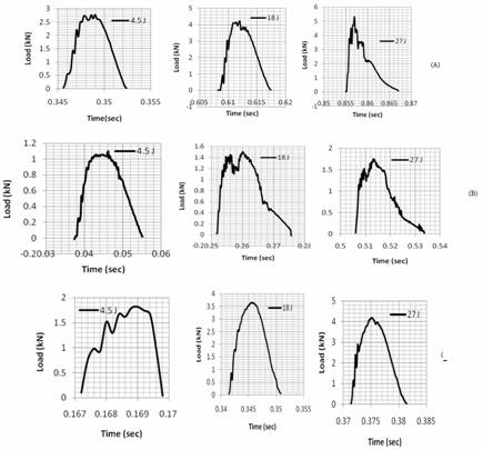
Figure 2. Impact load-time response of composites used in this study: (A) GFRP, (B)
KGNFRP, (C) NFRP
Properties such as the peak loads and ductility index obtained from the load-time response are presented as Figures 3- 5.
Figures 6-14 present the scanning electron microscope (SEM) micrograph of the front view of the impacted samples.
Figure 3. Effect of fiber type and combination on peak load of composites at different impact energies
Figure 4. Comparison of effects of fiber type and combination on peak load of composites at different impact energies using concept of normalization
Figure 5. Ductility index of composites at different impact energies
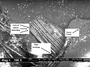
Figure 6. SEM Micrograph of Glass Fiber Reinforced Polyester(GFRP)
Impacted at Energy of 27 J
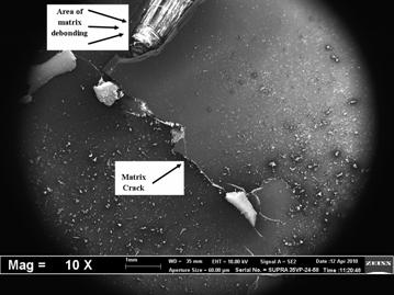
Figure 7. SEM Micrograph of Kevlar Fiber Reinforced Polyester (KFRP)
Impacted at Energy of 27J
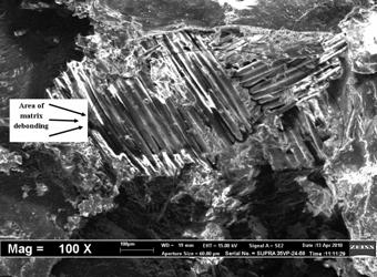
Figure 8. SEM Micrograph of Nylon Fiber Reinforced Polyester (NFRP)
Impacted at Energy of 27J
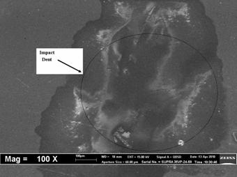
Figure 9. SEM Micrograph of Local Nylon Fiber Reinforced Polyester (LNFRP)
Impacted at Energy of 27J
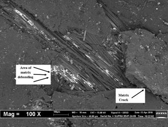
Figure 10. SEM Micrograph of Kevlar-Glass Fiber Reinforced Polyester (KGFRP)
Impacted at Energy of 27J
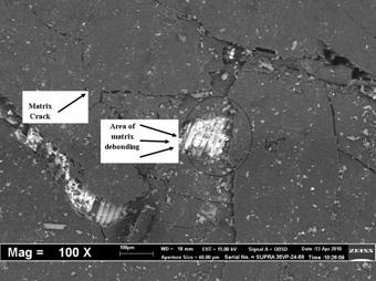
Figure 11. SEM Micrograph of Glass-Nylon Fiber Reinforced Polyester (GNFRP)
Impacted at Energy of 27J
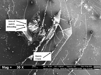
Figure 12. SEM Micrograph of Glass- Local Nylon Fiber Reinforced Polyester (GLNFRP)
Impacted at Energy of 27J
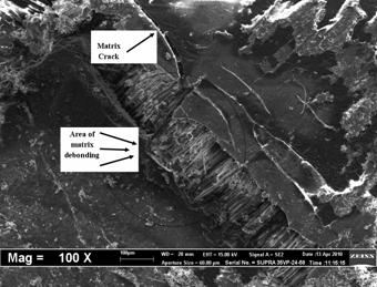
Figure 13. SEM Micrograph of Kevlar-Glass-Nylon Fiber Reinforced Polyester (KGNFRP)
Impacted at Energy of 27J
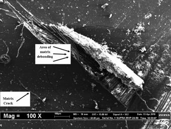
Figure 14. SEM Micrograph of Kevlar-Glass- Local Nylon Fiber Reinforced Polyester (KGLNFRP)
Impacted at Energy of 27J
Discussion
The shape of the load-time response curves’ indicated that all the samples tested at impact energy of 4.5 J exhibited load-time response that is symmetrical with equal loading and unloading except KGLNFRP and KGNFRP that showed slight tilt from the position of symmetry. This is an indication that samples tested at this impact energy were essentially undamaged [9]. At most, little dent at the point of impact as a result of impact force was only observed in some of the samples. As the impact was increased to 18 J, there was change in slope of the load-time response curve for most of the samples. The load-time response of LNFRP was still symmetrical, while those of some samples were asymmetrical. The KGLNFRP showed very little deviation from symmetry. At impact energy of 27 J, all the load-time responses were unsymmetrical in shape, although to lesser extent for the LNRFP, GLNFRP and KGLNFRP. The extent of damage was more at this impact energy level for all the samples when compared to impact energy of 18 J. These observations indicated that increase in impact energy results into more matrix cracking and fiber breakages and splits along the fiber direction [5]. However, there was no penetration or perforation of any of the samples at these impact energies.
As expected, the peak load (Figure 3) which is the maximum load that a laminate can sustain before major damage [7] was found to increase with increase in impact energy except for KFRP, GNFRP and KGFRP, where the peak load at 18 J was higher than that of impact energy of 27 J. At impact energies of 18 J and 27 J, the GLNFRP had the highest peak load. This was an indication that it was stiffest of all the samples tested and therefore, absorbed and sustained more load. Stiffer materials deform less and carry higher load [5]. This observation could be attributed to the compactness of the local nylon fiber that was combined with the glass fiber. The NFRP composite exhibited the least peak load; this was an indication that probably it was the most flexible of the composite samples. The KGFRP, GLNFRP and GNFRP composites showed peak load higher than their plain composites. This could be due to hybridization effect with the glass fiber introduced into the component contributing to the load bearing effect. The ter hybrid of Kevlar-glass-nylon (KGN) showed the least peak load among the hybrids, but the difference was not too evident when compared to the plain composites of nylon and Kevlar. The KGLNFRP exhibited tremendous level of load bearing capacity, in terms of stiffness when compared to other hybrids, nevertheless, with exception of glass- local nylon (GLN) hybrid and plain LNFRP composites.
Sample thickness has effect on load bearing and energy absorption capability of a material. Despite the fact that same ply of samples were prepared, differences in thickness were obtained because of the fiber nature. The fibers have different numbers of strands making up the weave, therefore different fiber thicknesses resulting to different composite sample thicknesses. Due to this, the concept of normalization (Figure 4) was adopted where the ratio of peak load to the thickness of each sample was taken. It was observed that there was tremendous difference between the normalized peak load and the original peak load.
The ductility index which is the ratio of the area under the post peak to the pre-peak load in the load-time response [5] showed that the KFRP showed highest ductility index at impact energy of 27 J (Figure 5). This indicated that most of the load was sustained at post peak. Therefore, the KFRP could sustain load after considerable damage without leading to catastrophic failure on impact. Low DI indicates that a larger amount of energy is required to initiate damage, but it also indicates that if damage does occur, little additional energy is required to cause total failure [24]. Despite other samples having ductility index (DI) above two at the impact energy of 27 J, the hybrid composite of KGNFRP had DI higher than plain glass fiber composites and other composites.
Matrix cracks, matrix debonding and fiber breakage were observed in GFRP sample (Figure 6). Some of these failure modes were also observed on the other samples, but the level differed from sample to sample. The NFRP (Figure 8) showed highest extensive matrix crack and debonding when compared to other composite samples, indicating that there was probably no proper fiber - matrix adhesion and resin penetration of the fiber mat because of its high tightness of weave. Effect of hybridization is evident in Figures. 10-14 when compared to Figures6 and 8 respectively. The level of matrix cracks and matrix debonding are lower when compared to some of the monolithic composites samples. The fiber combination resulting from the use of the highest strain rate to failure material at the back face would have resulted to this observation, less damage at the front face and especially at the back face of the hybrid composites.
Conclusions
Drop weight impact response of composites laminates, fabricated from four different fibers and their combinations was studied. The peak load and the ductility index DI were analysed. The SEM micrographs of the impacted surfaces were also analysed. The following observations were made from the study:
Peak load generally increased with increase in test impact energy with GFRP having the highest on normalization and the hybrids KGFRP, GLNFRP, KGNFRP showing appreciable peak load.
70% of the composites showed equal area on loading and unloading after peak load at test impact energy of 4.5 J, indicating little or no damage at that test energy. It is evident that most of the laminates will not fail catastrophically under the impact energy investigated because they have ductility index above 1.
Hybridization of the fiber mats had effect on the impact response of the materials as it reduced the level of matrix crack, debonding and fiber crack in the laminates.
Acknowledgements
Authors would like to acknowledge Universiti Sains Malaysia (USM) for the use of their equipment in conducting the research. The authors also wish to acknowledge Education Trust Fund, Science and Technology Education Post-Basic (STEP-B) Project 2010 Innovators of Tomorrow (IOT) and Ahmadu Bello University Board of Research for contributing funds for the project.
References
1. Arun K.V., Basavarajappa S., Sherigara B.S., Damage Characterization of Glass/Textile Fabric Polymer Hybrid Composites in Sea Water Environment, Materials and Design, 2010, 31, p 903-939.
2. Wan Y.Z., Wang Y.L., He F., Huang Y., Jiang H.J., Mechanical Performance of Hybrid Bisaleimide Composites Reinforced with Three Dimentional Braid Carbon and Kevlar Fabrics, Composites: Part A, 2007, 38, p. 495-504.
3. Hosseinzadeh R., Shokrieh M.M., Lessard L., Damage Behaviour of Fiber Reinforced Composites Reinforced Plates Subjected to Drop Weight Impacts, Composites Science and Technology, 2006, 66, p. 61-68.
4. Thanomsipl C., Hogg P.J., Penetration Impact Resistance of Hybrid Composites on Commingled Yarn Fabrics, Composites Science and Technology, 2003, 63, 467-482.
5. Sohn M.S., Hu X.Z., Kim J.K., Walker L., Impact Damage Characterization of Carbon Fiber/Epoxy Composites with Multi-Layer Reinforcement, Composites: Part B, 2000, p. 31681- 31691.
6. Shahkarami A., Cepus E., Vaziri R., Poursortip A., Material Response to Ballistic Impact In: Light Weight Ballistic Composite for Military and Law Enforcement Application edited by Ashok Bhtnagar, CRC Press, Wood Head Publishing Limited Cambridge, 2006, 73-89.
7. Kim J.K., Sham M.L., Sohn M.S., Hamada H., Effect of Hybrid Layers with Different Silane Coupling Agents on Impact Response of Glass Fabric Reinforced Vinylester Matrix Composites, Polymers, 2001, 42, p. 7455-7460.
8. Park R., Jang J., The of Hybridization on the Mechanical performance of Aramid / Polyethylene Intraply Fabric Composites, Composites Science and Technology, 1998, 58, p. 1621-1628.
9. Hosur M.H., Abdullah M., Jeelani S., Studies on the Low Velocity Impact Response of Woven Hybrid Composites, Composites Structures, 2005, 67, p. 253-262.
10. Ramos V.D., Da Costa H.M., Soares V.L.P., Nascimento R.S.V., Hybrid Composites of Epoxy Modified Resin with Carboxyl Terminated Butadiene Acrilonitrile Copolymer and Fly Ash Microspheres, Polymer Testing, 2005, 24, 219-226.
11. Shyr T.W., Pan Y.H., Low Velocity Impact Response of Hollow Core Sandwich Laminates and Interplay Hybrid Laminate, Composite Structures, 2004, 64, p. 189-198.
12. Dutra R.C.L., Soares B.G., Campos E.A., Silva J.L. G., Hybrid Composites Based on Polypropylene and Carbon Fiber and Epoxy Matrix, Polymer, 2000, 41, p. 3841-3849.
13. Roger L.E., Ballistic Impact Resistance Graphite Epoxy Composites with Shape Memory Alloy and Extended Chain Polyethylene Spectra Hybrid Component, M.Sc. Thesis, 1996, Virginia Polytechnic Institute and State University.
14. Wong W., Horsfall I., Champion S.M., Watson C.H., The Effect of Matrix Type on the Ballistic and Mechanical Performance of E-glass Composite Armour, 19th International Symposium of Ballistics, 7-11 May 2001, Interlaken, Switzerland.
15. Muhi R.J., Najim F., De Moura M.F.S.F., The Effect of Hybridization on the GFRP Behavior under High Impact Velocity, Composites: Part B, 2009, 40, p. 798-803.
16. Saha N., Banerjee A.N., Mitra B.C., Tensile Behaviour of Unidirectional Polyethylene Glass Fiber/PMMA Hybrid Composite Laminates, Polymer, 1996, 37, p. 699-701.
17. Singh S., Mohanty A.K., Misra M., Hybrid Bio-Composite from Talc and Wood Fiber and Bio-Plastic: Fabrication and Characterization, Composites: Part A, 2010, p. 304-312.
18. Mishra S., Mohanty A.K., Drzal L.T., Misra M., Pirja S., Niyak S.K., Tripathy S.S., Studies on the Mechanical Performance of Biofibre/Glass Reinforced Polyester Hybrid Composites, Composites Science and Technology, 2003, 63, p. 1377-1383.
19. Himani J., Purnima J., Development of Glass Fiber Wollastonite Reinforced Polypropylene Hybrid Composite: Mechanical Properties and Morphology, Material Science and Engineering A, 2009, doi: 10.1016/j.msea.2009.11.039.
20. Bakar M., Djaider F., Effect of Plasticizers Content on the Mechanical Properties of Unsaturated Polyester Resin, Journal of Thermoplastic Composite Materials, 2007, 20, p. 53-64.
21. Isa, M.T., Development of High Performance Fiber Reinforced Polymer for Impact Damage Resistance Application, PhD Dissertation unpublished, 2011, Ahmadu Bello University, Zaria, Nigeria.
22. Isa M.T., Ahmed A.S, Aderemi B.O, Effect of Fabrication and Post Fabrication Treatment on Properties of Glass Reinforced Polyester Composite, Nigerian Journal of Engineering, 2006, 13(1), p. 97-103.
23. Isa M.T., Ahmed A.S., Aderemi B.O., Taib R.M., Mohammed-Dabo I.M., Effect of Fiber Type and Combinations on the Mechanical, Physical and Thermal Stability Properties of Polyester Hybrid Composites, Composites: Part B, 2103, 52, p. 217-223.
24. Evensen T., Mahinfalah M., Jarzar R.N., Berg J.M., Effect of Gas Plasma Surface Treatment on Spectra 900 and Spectra 1000 Fabric Laminates composites, 16th International Conference on Composite Materials, 2007, Kyoto, Japan, p. 1-9.