Fractal shaped Sierpinski on EBG structured ground plane
Boddapati Taraka Phani MADHAV1, Venkata Gopala Krishna Murthy PISIPATI2, Habibulla KHAN2, Dogiparthi UJWALA1
1Associate Professor, Department of ECE, K L University, Guntur DT, AP, India
2Professor, Department of ECE, K L University, Guntur DT, AP, India
Emails: btpmadhav@kluniversity.in, vgkmpisipati@gmail.com, habibulla@kluniversity.in, ujwala@kluniversity.in
Abstract
This paper presents the performance evaluation of a novel electromagnetic band gap (EBG) structured Sierpinski fractal antenna. The wide band gap is achieved in EBG structure by maintaining the radius to period ratio of the fractal patterns larger than 0.5 in the whole structure. In this work fractal shaped designs of different iterations are examined with change in EBG slots on the ground plane. A simple coaxial feeding is used in the design of the antenna. As the iteration order of the Sierpinski radiator increases, the bandwidth is increases and the surface wave losses are decreased.
Keywords
Fractal antenna; Wide slot antenna; Sierpinski; Electromagnetic band gap
Introduction
Electromagnetic band gap (EBG) structures are periodic patterns that exhibit a band of frequencies in which the electromagnetic propagation is not allowed in microwave range [1-4]. EBG structures have a wide range of applications in antennas, amplifiers, microwave cavities etc. In micro strip technology the EBG structure is obtained by creating a one dimensional periodic pattern etched in ground plane with different shapes and radius to period ratio lower than 0.5. Usually four to five periods are needed to provide good band gap characteristics and therefore a large physical space is required for integrating the EBG into system [5-8]. The objective of the paper is to propose a new fractal structure that significantly improves the compatibility of both the requirements of bandwidth enhancement and surface wave losses reduction [9-10].
Compact and wide band antennas are required in the modern communication systems for different applications. Micro strip wide slot antennas are very much required to achieve wide operating bandwidth. The impedance bandwidth of printed wide slot antennas can be easily controlled by the coupling between the tuning stub and the slot in order to enhance the bandwidth or reduce the size of the wide slot antennas, the fractal technique has been applied in to wide slot radiators [11-15]. Fractal antenna is an emerging field that employs fractal concepts for developing new types on antennas with notable characteristics such as multiband, miniature and high dielectric elements. Due to their method of generations, some fractals possess unique features such as self-similarity, which allows for multiband or wideband antenna designs [16-19]. Also the space filling property, when applied to the slot antenna element, leads to reduce the total area occupied by the antenna.
In this paper we design a novel fractal shaped antenna of different iterations on EBG structured ground plane, even though the space filling property of the Sierpinski fractals tends to fill the area occupied by the antenna, the bandwidth of the slot antenna increases with the increase in the number of iterations [20]. Such as increase in the bandwidth results from a decline in the lower edge of the operating frequency band of the wide slot antenna, with the upper edge of the operating frequency band of the wide slot antenna remaining unchanged. Generally the lower edge of the operating frequency band of the wide slot antenna depends on a side length of the slot [21]. In this work fractal geometry, which is placed as patch on the top side is improving the bandwidth of the antenna and the EBG structured ground plane on the lower side decreasing the surface wave losses associated problems. With the combination of fractal and EBG, the antenna performance characteristics are been improved, which can be used in the communication systems to work at multi bands with low loss.
Material and method
The current model is fabricated on FR4 substrate material with dielectric constant 4.4 and thickness 1.6 mm. The proposed antenna dimensional characteristics are 40X40X1.6 mm and the conventional coaxial feeding technique is implemented with impedance matching of 50 ohms at appropriate location in the geometry.
Antenna configuration
A new design of Sierpinski antenna configuration with different iterations placed on EBG structure is presented in this paper. This slot radiator using fractal shaped Sierpinski Square is shown in Figure 1. The fractal geometries are generated from an original square slot by an iteration application of a generator method, which divided a square slot into four portions with the same physical size. First iteration order is achieved when the upper right portion is filled with metal plate. The second iteration order antenna is divided by practicing the same generator method on the remaining portions of the first iteration order. Repeating this generator method continuously we can generate the nth order Sierpinski square plot geometry with the self-similar characteristics.
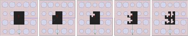
Figure 1. Different iterations of fractal antenna on EBG structured ground plane
The square slot has a side length of ‘a’. In this study the scale factor is 0.5. The antenna is designed on RT duroid substrate with dielectric constant 2.2 and thickness of 1.6mm. The Sierpinski fractal slot is printed on one side of the substrate and is fed by coaxial feeding on the other side. The end of the fed on the either side will be connected to SMA connector. The geometric dimensions of the antenna are given in Table 1. The input impedance at the edge of the slot is capacitive. The ground plane size is denoted by L. The antenna performance is analyzed by three dimensional finite element method software HFSS. The radius of the EBG structure slot on the ground plane is denoted by r. N number of cells are etched on the ground plane as shown in the Figure 1. The central frequency of the rejected band is obtained from λg = 2a, where λg is the guided wavelength. The radii distribution follows the relationship.
|
|
(1) |
where i = 0, 1, 2 …..
ri and rmax are the ith and max fractal hexagonal cell radii respectively. Z/L is the normalized longitudinal position in the circuit (Z=0 corresponds to the central point) and T (Z/L) is the tapering Kaiser function.
|
|
(2) |

Results and discussion
The simulated reflection coefficient of the proposed antenna for the iteration zero to four is shown in the Figure2. Iteration 0 is a conventional square slot antenna. The resonant frequency of the conventional square slot antenna is -35.88 dB. The original resonant frequency of the conventional slot is changing as the iteration order increases, while a new resonance is created nearer to the original resonance. It is clearly observed that as the iteration order increases from 0th to 4rd order the first resonance frequency is having better return loss. Antenna is resonating at different frequencies by changing the iterations and the gain is slightly decreasing from 0th iteration to 4th iteration.
A wide stop band is achieved for r/a = 0.55, which can be useful for the design of antenna and other devices. Considering the losses in the connection, the non-idealities of the fabrication such as in the dimensions of the shape of fractal and a slight difference of the dielectric constant with respect to the given value, the simulated results are presented. Bandwidth enhancement is achieved from these models when compared with normal rectangular patch antenna and those results are tabulated in the Table 1. In order to gain insight in to any undesired effects due to coupling of radiated waves we have analyzed the radiating characteristics as a function of frequency. According to the relationship 1 - |s11|2 - |s21|2 for the simulated structures. The metallic and dielectric losses are considered negligible in order to isolate the undesired radiant effects.
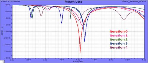
Figure 2. Return loss Vs frequency for different iterations
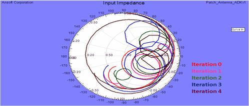
Figure 3. Input impedance Smith chart
Table 1. Antenna output parameters
|
S.No |
Iterations |
Resonant frequency |
Return loss |
Gain in dB |
Bandwidth |
|
1 |
Iteration 0 |
4.05 GHz |
-35.88 dB |
8.59 dB |
0.3 % |
|
2 |
Iteration 1 |
4.1 GHz |
-15.47 dB |
8.35 dB |
0.3% |
|
3 |
Iteration 2 |
3.9, 5.3 GHz |
-11.68, -10.96 dB |
8.28 dB |
0.38 % |
|
4 |
Iteration 3 |
2.5, 3.4, 4.1 GHz |
-10.11, -13.89, -27.58 dB |
7.94 dB |
0.4% |
|
5 |
Iteration 4 |
2.6, 3.7, 4.1 GHz |
-10.33, -10.26, -15.19 dB |
7.7 dB |
0.42% |
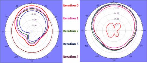
Figure 4. Radiation pattern at phi = 0° and phi = 90°
Table 2. Antenna parameters
|
S.No |
Parameter |
Iteration 0 |
Iteration 1 |
Iteration 2 |
Iteration 3 |
Iteration 4 |
|
1 |
Max U (w/sr) |
0.0061188 |
0.0034593 |
0.0033648 |
0.0018702 |
0.001251 |
|
2 |
Peak Directivity |
7.2411 |
6.9703 |
7.0279 |
6.4887 |
6.2203 |
|
3 |
Peak gain |
7.241 |
6.9347 |
7.0028 |
6.4274 |
6.1357 |
|
4 |
Peak realized gain |
7.1377 |
6.1497 |
6.5424 |
4.3303 |
3.7026 |
|
5 |
Radiated power (W) |
0.010619 |
0.0062366 |
0.0060166 |
0.003622 |
0.0025273 |
|
6 |
Accepted power (W) |
0.10619 |
0.0062687 |
0.0060382 |
0.0036566 |
0.0025621 |
|
7 |
Incident power (W) |
0.010773 |
0.0070688 |
0.0064631 |
0.0054273 |
0.0042458 |
|
8 |
Radiation efficiency |
0.99999 |
0.99409 |
0.99642 |
0.99056 |
0.98639 |
|
9 |
Front to back ratio |
49.769 |
51.773 |
59.482 |
57.34 |
58.382 |
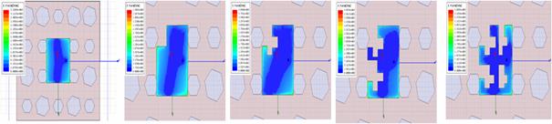
Figure 5. E-Field distributions at fundamental resonant frequency
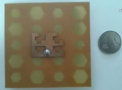
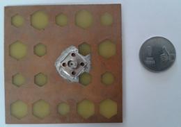
Figure 6. Fabricated model of the proposed antenna (Top view and back view)
The results show that iteration zero and one are resonating at single band with bandwidth enhancement of 0.3% over the conventional micro strip antenna. The iteration two is resonating at dual band with lesser gain and more bandwidth compare to iterations zero and one. Iterations three and four are resonating at triple band with high bandwidth compared to all the previous iterations. Figure 4 shows the radiation pattern at π =0° and π =90° for all iterations from zero and four. The radiation efficiency, peak gain and peak directivity of iteration zero is little bit more compared to other iterations. The front to back ratio is also less for iteration zero. Figure 5 shows that the simulated surface E-field distribution on the slot plane at the fundamental resonating frequency of each iteration. These plots are normalized at minimum and maximum values. From the results we observed most of the E-fields are concentrated on the bottom left portion of the plot. Figure 7 shows the measurement results of the fabricated prototype antenna. R&S ZNB-20 Vector Network Analyzer is used to measure the S-parameters of the prototyped model. Figure 7 shows the frequency Vs reflection coefficient and input impedance smith chart for the proposed model. From the Figure 7, it is been observed that the measured results are in very good agreement with the simulated results and impedance matching with VSWR 2:1 observed at resonating frequency.
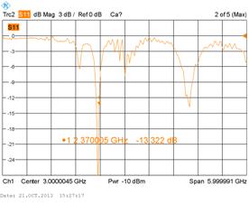
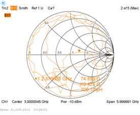
Figure 7. Measured results of return loss and input impedance for proposed model
Table 3. Maximum field data
|
S. No |
rE-Field |
Iteration 0 |
Iteration 1 |
Iteration 2 |
Iteration 3 |
Iteration 4 |
|
1 |
Total |
2.1479 V |
1.615 V |
1.5298 V |
1.1875 V |
0.9712 V |
|
2 |
X |
0.28681 V |
0.55179 V |
0.85267 V |
0.69762 V |
0.58946 V |
|
3 |
Y |
2.1452 V |
1.543 V |
1.3582 V |
0.9475 V |
0.75388 V |
|
4 |
Z |
0.91989 V |
0.79679 V |
0.83717 V |
0.67581 V |
0.57024 V |
|
5 |
Phi |
2.139 V |
1.5944 V |
1.5421 V |
1.1599 V |
0.94224 V |
|
6 |
Theta |
2.1479 V |
1.6053 V |
1.5713 V |
1.1811 V |
0.9668 V |
|
7 |
LHCP |
1.5334 V |
1.0632 V |
1.088 V |
0.91679 V |
0.72292 V |
|
8 |
RHCP |
1.5373 V |
1.2229 V |
1.1767 V |
0.90109 V |
0.74232 V |
Table 3 gives the maximum field data of the model at fundamental resonating frequency. At different iterations of the antenna, the maximum field data is tabulated with left hand circular polarization and right hand circular polarization in theta and phi directions also.
Conclusions
In this work the Sierpinski fractal shaped slot with EBG structure is employed to increase the band width by decreasing the surface wave losses.
Ø The amount of power that is lost to the load and does not return as
a reflection i.e. return loss is been represented with S11 parameter. The
return loss of ![]() less than or equal to -10dB and VSWR of
less than 2 are attained for all the iterations at resonant frequencies.
Iteration 0 and 1 are resonating at single band, whereas iteration 2 is
resonating at dual band with 0.08% improvement in the bandwidth. Iteration 3
and 4 are resonating at triple band with 0.1% improvement in the bandwidth
compared to iteration 0 and 1. The proposed model is giving gain of 7.7 dB
which is quite high for single radiating element antenna but compared to first
iteration it is less by 0.89 dB.
less than or equal to -10dB and VSWR of
less than 2 are attained for all the iterations at resonant frequencies.
Iteration 0 and 1 are resonating at single band, whereas iteration 2 is
resonating at dual band with 0.08% improvement in the bandwidth. Iteration 3
and 4 are resonating at triple band with 0.1% improvement in the bandwidth
compared to iteration 0 and 1. The proposed model is giving gain of 7.7 dB
which is quite high for single radiating element antenna but compared to first
iteration it is less by 0.89 dB.
Ø The present design periodic patterns based fractal geometrics have been applied to one dimensional EBG micro strip structures. The ripple that appears the pass band is reduced while the width of band gap is increased by modulating the fractal period with the same function. As a result of this the size of the device is compacted.
Ø Therefore the proposed antenna is feasible for use of a low profile, low cost, high bandwidth antenna for supporting various wireless communication services.
Acknowledgements
Authors like to express their thanks to the department of ECE and management of K L University for their support and encouragement during this work. Madhav further likes to express his gratitude towards Er. K. Satyanarayana Garu, President, KLU for providing excellent facilities in the research centre of LCRC to carry out this work. This work is supported by Department of Science and Technology (SR/FST/EIT-316/2012) through FIST program.
References
1. Mosallie H., Sarabandi K., A compact wide band EBG structured utilizing embedded resonant circuits, IEEE antennas wireless propag., 2005, 4, p.5-8.
2. Radisic V., Qian Y., Coccili R., and Itoh T., Novel 2-D photonic band gap structure for microstrip lines, IEEE Microwave guided wave lett, 1998, 8(2), p.69-71.
3. Madhav B.T.P., Krishnam N.Y., Kumar G.S., Rahul R., Fractal aperture EBG ground structured dual band planar slot antenna, International journal of applied engineering research, 2014, 9(5), p. 515-524.
4. Madhav B.T.P., Vaishnavi G., Manichandana V., Harinath Reddy Ch, Ravi Teja S., Sesi Kumar J., Compact Sierpinski carpet antenna on destructive ground plane, International journal of applied engineering research, 2013, 8(4) , p. 343-352.
5. Dios Ruiz J., Felix L. M., Hinojosa J., Novel compact wide band EBG structure based on tapered 1-D Koch fractal patterns, IEEE Antennas and wireless propagation letters, 2011, 10, p.1104-1107.
6. Kahrizi M., Sarkar T.K., Maricevic Z.A., Analysis of a wide radiating slot in the ground plane of a microstrip line, IEEE Trans.antenna propag, 1993, 41(1), p.29-37.
7. Menon S.K, Lethakumary B., Aanandan C.N, Vasudevan K.M., A novel EBG structured ground plane for microstrip antennas, IEEE Antennas and propagation, 2005, 2A, p.578-581.
8. Kawakami Y., Hori T., Mitoshi Y., Ryo C, Reflection characteristics of finite EBG structured on finite ground plane, Antenna technology, 2008, p.183-186.
9. Steven B.R., Drayton H., Design of broadband dipole in close proximity to an EBG ground plane, IEEE Antenna and propagation, 2008, 50, p.52-64.
10. Liu Y.F., Lau K.L., Xue Q., Chan C.H., Experimental studies of printed wide-slot antenna for wideband applications, IEEE Antennas wireless propag., 2004, 3, p.273-275.
11. Madhav B.T.P., Chhatkuli S., Manikantaprasanth A., Bhargav Y., Dinesh Naga Venkata Sai U., Feeraz S., Measurement of dimensional characteristics of microstrip antenna based on mathematical formulation, International journal of applied Engineering Research, 2014, 9(9), p. 1063-1074.
12. Chen W.L., Wang G.M., Zhang C.X., Bandwidth enhancement of a microstrip line fed printed by slot antenna with a fractal shaped slot, IEEE Trans. antennas propag, 2009, 57(7), p.2176-2179.
13. Anguera J., Puente C., Borja C., Soler J., Fractal shaped antennas: A review, Wiley encyc. RF microw.engrg, 2005, 2, p.1620-1635.
14. Werner D.H., Ganguly S., An over view of fractal antenna engineering research, IEEE Trans. Antenna’s propag. Mag., 2003, 45(1), p.38-57.
15. Sung Y.J., Bandwidth enhancement of a wide slot using fractal-shaped Sierpinski, IEEE Transactions on antenna and propagations, 2011, 59(8), p.3076-3079.
16. Suganthi.S, Raghavan.s, Kumar, D.David Neel pon, Thilagar, S.Hosimin, Planar fractal antennas for wireless devices, Electronics computer technology (ICECT), 2011, 1, p.98-108.
17. Sayidmarie K.H., Al-Shabkoon, E.U., Feasibility of focused fractal antenna arrays, Information and communication technologies, 2006, 2, p.2224-2229.
18. Sadasivarao B., Madhav B. T. P., Analysis of hybrid slot antenna based on substrate permittivity, ARPN Journal of engineering and applied sciences, 2014, 9(6), p.885-890.
19. Azari A., A new super wideband fractal micro strip antenna,” IEEE Transactions on Antennas and propag, 2011, 59, p.1724-1727.
20. Yao N., Shi X.W., Analysis of the multiband behavior on Sierpinski carpet fractal antennas,” Microwave conference proceedings APMC, Vol.4, Dec 2005.
21. Kotamraju S.K., Madhav B.T.P., Krishna T.V.R., Khan H., Compact microstrip defected ground structured antenna for reduction of harmonics and cross polarized radiations, AMTA-2013, US Columbia, Oct 8th-11th.