Design and analysis of microstrip slot array antenna configuration for bandwidth enhancement
Duvvuri Sri RAMKIRAN1, Boddapati Taraka Phani MADHAV1, Nimmagadda HARITHA2, Ravuri Sree RAMYA2, Kalyani M. VINDHYA2, Sai P. ABHISHEK2
1Associate Professor, Dept of ECE, K L University, Guntur DT, AP, India
2Project Students, Dept of ECE, K L University, Guntur DT, AP, India
Emails: btpmadhav@kluniversity.in, ramkiranduvvuri@kluniversity.in, abhishek02792@gmail.com, vindhya.m95@gmail.com, ravurisriramya@gmail.com
Abstract
A bandwidth-enhanced Microstrip slotted array antenna is fabricated on an electrically-thin substrate to provide an economical solution for communication applications. To improve the impedance bandwidth of a rectangular micro strip patch without having any impact on its radiation characteristics, we perform etching of straight slot which is parallel and near to top side of the patch. For demonstrating the usefulness of the suggested technique, a planar array of dimension 6X6 with a side-lobe of 25 dB in both the E and H-planes are studied and fabricated on the FR4 substrate with 0.787 mm thickness. Simulation studies will be carried out on Method of Moments based EM Tool and analysis of the model is done by changing different operational parameters like the width of the slot, array element spacing, and array pattern. The antenna output parameters will be studied by changing substrate materials, εr ranging from 2 to 4.4 and complete analysis is presented in a detailed manner.
Keywords
Array antenna; Bandwidth enhancement; Impedance bandwidth; Method of moments
Introduction
Microstrip antennas are very useful candidates in communication systems because of their simple geometry and are relatively inexpensive to design and manufacture [1]. A single layered FR4 is used as substrate in designing a micro strip antenna array, which is having dielectric constant of 4.4 and thickness 0.787 mm. We implemented the current models on a thin substrate. The thick substrate has two disadvantages. One is more energy dissipation by antenna and other is unwanted surface wave propagation, so which will decrease energy, efficiency and deteriorate the energy pattern. By increasing thickness of the substrate we can attain the bandwidth improvement, but there is some limitation on the height of the substrate, over which the antenna performance will be degraded [2].
Impedance matching will play a vital role in the antenna performance, especially for the bandwidth improvement. Choosing proper impedance matching network, while connecting array configuration is very much needed for good radiation mechanism. Because of the variations, nature of the inherent narrow bandwidth on conventional microstrip patch antenna is observed. Except for single-feed circularly polarized elements, the resonant behaviour of the input impedance has an effect on bandwidth limitation and not due to the radiation pattern or gain variations [3]. To increase the bandwidth by a factor of at least 3.9, we use an optimally designed impedance-matching network. Therefore, a broadband impedance matching is proposed to increase the bandwidth [4].
In thick microstrip antennas, probe inductance prevents matching of the patch impedance to the input connector. The probe inductance can be tuned out with a capacitive gap. To maintain simplified construction the gap will be etched on the patch surface. The use of a single probe-compensated feed results in distortion of radiation pattern, high cross polarization and low efficiency because of higher-order modes and surface-wave generation [5]. Two-probe feeding is used to overcome these problems and to produce a wide-band antenna with good radiation pattern control and high efficiency [6].
To double the bandwidth of rectangular micro strip patch antennas, capacitive excited short circuit parasitic elements are located at their radiating edges. It is shown that the bandwidth improvement is independent of the coupling capacitance. To produce multiple resonances we arrange the right angle slot of the long arm parallel to non-radiating edges. The length of the long arm is more than ninety percent of the patch and short is forty percent. There are many methods to improve Uni-polar bandwidth. The impedance bandwidth can be raised by producing TM at the basic TM10 mode. Moreover, these slots will disturb the fundamental mode current division particularly at high frequency [7].
Novel bandwidth of micro strip antennas can be enhanced by loading a U-shaped slot and a pair of right angled slots. Dimensions required for the U shaped slot and the right-angled slots can be determined experimentally. The obtained antenna bandwidth when compared with an un-slotted rectangular micro strip antenna will be as large as about 2.4. The other simplest technique to increase the impedance bandwidth in this communication is to use two parasitic straight slots etched parallel and near to its non-radiating edge [8]. This is simple because manufacturing intricacy, price and time can be reduced. Depending on the slot configuration, a 6x6 array is used in antenna for communication. These methods is used in communication sensors and also in inter vehicle communication system. The benefits are light gravity, low shape, an easy fabrication and low expenses of large scale manufacturing. Planar arrays afford more symmetrical patterns with lower side lobes and the ability to scan the main beam toward any point in space. These arrays are mainly used in the communication systems to transmit the signals with high gain.
Material and method
All the models are designed and simulated using Method of Moments based electromagnetic solver IE3D tool. FR4 substrate material with dielectric constant 4.4 with thickness 1.6 mm is used in these designs. Quarter wave transformers are incorporated in the array models for impedance matching. Basically starting with single element patch, subsequent models are designed with 2x2, 4x4 and 6X6 array configurations.
Antenna geometry
The array factor for linear array is:
|
|
(1) |
Io represents the magnitude of the excitation current at the centre element of the array so all other Im currents are normalized to the centre element's current.
If we have M elements along the x-axis the array factor is given by the following equation
|
|
(2) |
where Iox is the current of the centre element if an odd number of elements or center elements, if an even number of elements and we are removing the restriction that the currents have equal amplitudes. Now, if we have N elements along the y axis with an inter element spacing of dy and a progressive phase shift βy.
|
|
(3) |
where Ioy is the current of the centre element if an odd number of elements or centre elements, if an even number of elements and α=γ=90° and β=0° in equation (1).
For a large array, with its maximum near broad side, the elevation plane half-power beam width is
|
|
(4) |
where Θx0 and Θy0 indicates the half power beam-width of M element and N element broadside linear array respectively.
Here
U(θ, Ф) = Power density from the planar array, P watt/m2
θ o = Direction of the maximum beam in the elevation plane
Фo = Direction of the maximum beam in the horizontal plane
(θ o, Фo) = direction of the maximum beam scanning in the phase Imn current amplitude in the mnth element
α = Progressive current phase shift
β = constant
phase shift 2 θ /![]()
M = Total elements in X-direction
N = Total elements in Y-direction
dx, dy =spacing between adjacent elements in x and y direction
AF(θ,Ф) = Array factor
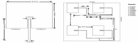
Figure 1a. Single element patch model, 1b. 2x2 Array model
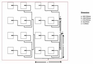
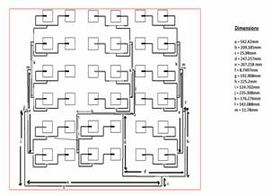
Figure 2. (a) 4X4 array model (b) 6x6 array model
A single element patch is designed by using the method of moments based EM tool IE3D and after that the array models are constructed for 2x2, 4x4 and 6x6. Quarter wave transformers are used in the design of arrays for impedance matching. To simulate single element, 2x2 and a 4x4 array model the computational facilities that are available in our university is sufficient with the RAM availability, but when the number of elements are increased we need higher computational facilities to get the result in time. In this method, an equivalent circuit network was built up by combining the equivalent circuit model of the path and that of the feeding network. Meanwhile, the mutual couplings among patches are also considered while incorporating their equivalent circuits. Figures 1 and 2 are showing all the 4 models with their dimensional characteristics.
Results and discussion
An antenna should be perfect radiator, rather than perfect absorber. The amount of radiated power returned back through the port can be calculated for finding return loss at that resonating frequency. For the resonant frequencies the return loss should be less than -10dB i.e. S11<-10 dB. Figure 4 shows the return loss curve for all the 4 models and it is observed that for a 6x6 array model an impedance bandwidth of 16% is attained.
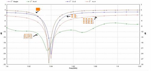
Figure 4. Return loss Vs frequency
VSWR is a function of reflection coefficient, which describes the power reflected from the antenna. Figure 5 shows the VSWR curve for 4 models and it is observed that all the models are maintaining 2:1 ratio of VSWR at the resonating frequency.
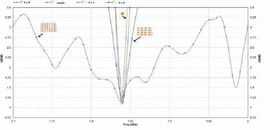
Figure 5. VSWR Vs frequency
Antenna impedance is presented as the ratio of voltage to the current at the antenna’s terminals. Figure 6 shows the impedance characteristics of the model and it is noted that almost 50ohms is obtained at the desired frequency.
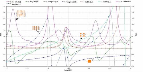
Figure 6. Z-Parameters for all the models
Antenna gain describes how much power is transmitted in the direction of peak radiation to that of an isotropic source. By increasing the order of elements it is noted that the gain of 3, 8, 12 and14dB obtained from the models. A 6x6 array is giving maximum gain of 14dB at the resonant frequency and it can be observed from Figure 7.
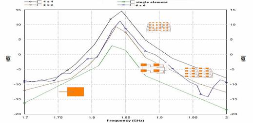
Figure 7. Gain Vs frequency
The radiation performance of the entire array is evaluated by the array factor technique and the array factor is calculated from the scattering parameters of our equivalent circuit network. Calculated results are presented in Figure 8 for a single element, 2x2, 4x4 and 6x6.
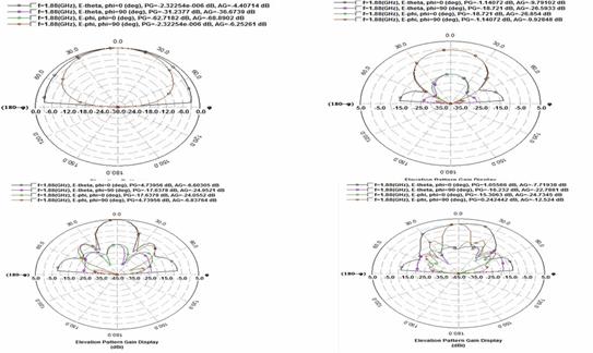
Figure 8. Radiation characteristics of the models
Table 1 showing all the antenna parameters like resonant frequency, directivity, radiation efficiency, gain and 3dB beam width. The efficiency of the antenna is more for 6X6 array model with high gain of more than 12 dB.
Table 1. Antenna parameters for single, 2x2, 4x4 and 6x6 models
|
S.NO |
Parameter |
Single element |
2 x 2 |
4 x 4 |
6 x 6 |
|
1 |
Frequency (GHz) |
1.836 |
1.84 |
1.828 |
1.842 |
|
2 |
Incident Power |
0.01 W |
0.01 W |
0.01 W |
0.01 W |
|
3 |
Radiated Power |
0.00688558 W |
0.00597487 W |
0.0025073 W |
0.00210908W |
|
4 |
Directivity |
6.20227 dBi |
12.1549 dBi |
17.811 dBi |
17.968 dBi |
|
5 |
Radiation Efficiency |
71.3948% |
69.9562% |
71.6808% |
71.676% |
|
6 |
Antenna Efficiency |
68.8558% |
69.7487% |
65.073% |
71.09% |
|
7 |
Gain |
4.58167 dBi |
9.9182 dBi |
11.80 dBi |
12.02 dBi |
|
8 |
3db Beam Width |
(84.6649, 170.267) deg. |
(46.2137, 50.2583) deg. |
(22.9598,24.1022)deg. |
(15.033, 30.8845) deg. |
Figure 9 shows the current distribution over the surface of the antenna with its intensity readings. On the surface of the antenna the orientation of current elements at a particular frequency is presented with colour scaling. With respect to the current scaling we can identify the mode of propagation in the current models.
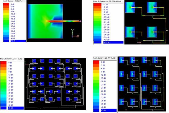
Figure 9. Current distribution at resonant frequency
The basic 6x6 array model is modified by placing slots on top edge as shown in the Figure 10(a) and slot at the centre point on the patch as shown in Figure10(b).
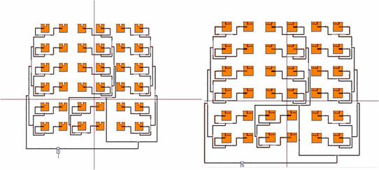
Figure 10. (a) 6x6 array open slot, (b) closed slot model
By placing these slots we observed the change in resonant frequencies of the antenna. For an open slot model shown in Figure 11 antenna is resonating at 1.6,1.68 and 1.98Ghz with return loss of -20,-32 and -14dB respectively. From the VSWR curve of Figure 12, 2:1 ratio is attained at the desired bands for both the models. Gain of 9dB for an open slot model 10dB for a closed slot model is observed from Figure 13.
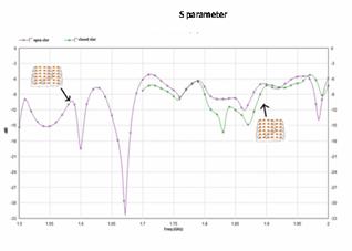
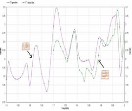
Figure 11. (a) Return loss Vs frequency of closed slot and open slot models (b) VSWR Vs frequency of closed slot and open slot models
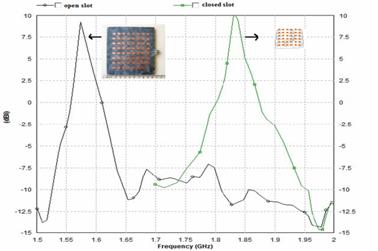
Figure 12. Frequency Vs gain of 6X6 closed (measured) and open slot (simulated) array models
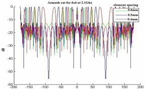
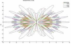
Figure 13. Radiation pattern Azimuth cut in 2D and polar planes at 2.1 GHz
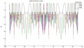
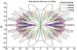
Figure 14. Radiation pattern Azimuth cut in 2D and polar planes at 1.9 GHz
All the antenna parameters for the 6x6 open and closed slots are tabulated in Table 2.
Table 2. Antenna parameters
|
S NO |
Parameters |
6 x 6 closed slot |
6 x 6 open slot |
|
1 |
Frequency |
1.832 ghz |
1.672ghz |
|
2 |
Incident power |
0.01 W |
0.01W |
|
3 |
Radiated power |
0.00171666 W |
5.20438e-005 W |
|
4 |
Directivity |
12.9667 dBi |
17.2814 dBi |
|
5 |
Radiation efficiency |
17.678% |
0.521003% |
|
6 |
Antenna efficiency |
17.1666% |
0.520438% |
|
7 |
Gain |
9.3135 dBi |
10.5549 dBi |
|
8 |
3 db beam width |
(15.3368, 29.442) deg. |
(16.7832, 31.6625) deg. |
The simulation results are giving the performance characteristics of the model in virtual environment. Once by attaining radiation characteristics of the model based on element spacing, then we can optimize the model and fabricate the model.
Conclusions
The designed models are showing excellent gain and directivity at the resonating frequencies with high radiation efficiency. Bandwidth enhancement of more than 2-3% is attained when compared with basic models. The proposed models are giving excellent radiation characteristics with minimum return loss at desired frequencies. Some special observations from the current study are
§ We observed from the fig 13 and 14, that the inter element spacing between the elements for an N element array is increased then the beam width will be decreased.
§ From this study we observed that for the uniformly spaced arrays the maximum space length is a half-length to avoid grating lobes.
§ We also observed that the array element spacing is non uniform then aliasing can be avoided. Particularly if the spacing is not the multiples of each other.
Acknowledgments:
Authors would like to express their deep gratitude towards the ECE department and the management of K L University for their support and encouragement during this work. Authors also like to express their thanks to the department of science and technology through SR/FST/ETI-316/2012 FIST program.
References
1. Constantine A., Balanis, Antenna theory, analysis and design, John Wiley & Sons, Inc., Hoboken, New Jersey, 2005.
2. Liang H. and Ke W., 24-GHz Bandwidth-enhanced microstrip array printed on a single-layer electrically-thin substrate for automotive, applications”, IEEE Transactions on antennas and propagation, 2012, 60(5).
3. Pozar D.M., and Schaubert D.H., Microstrip antennas: the analysis and design of microstrip antennas and arrays, New York: IEEE Press, 1995.
4. Sze J.-Y. and Wong K.-L., Slotted rectangular microstrip antenna for bandwidth enhancement,” IEEE Trans. antennas propag., 2000,48(8), p. 1149–1152.
5. IE3D Package14.1 ed. Fremont, CA, Zeland Software, 2009.
6. Mohammad T. I., Mohammed N.S., Norbahiah M., and Baharudin Y., Analysis of broadband slotted microstrip patch antenna, IEEE Trans, 2008, AP-1-4244-2136.
7. Madhav B.T.P., Pisipati V.G.K.M., H. Khan, Prasad V.G.N.S., K. Kumar P., Bhavani K.V.L, and Datta Prasad P.V., Microstrip 2x2 square patch array antenna on K15 liquid crystal substrate, International journal of applied engineering research, 2011, 6(9), p. 1099-1104.
8. Wen-Chung L., Chao-Ming W., and Yen-Jui T., Parasitically loaded CPW-Fed monopole antenna for broadband operation, IEEE Transactions on antennas and popagation, 2011, 59(6).