The effect of plate heat exchanger’s geometry on heat transfer
Oana GIURGIU*, Angela PLEŞA and Dan OPRUŢA
Department of Mechanical Engineering, Technical University of Cluj-Napoca, Romania
E-mails: oana.giurgiu@termo.utcluj.ro; angela.plesa@termo.utcluj.ro;
* Corresponding author, Phone: +40744549988
Abstract
The study presents further Computational Fluid Dynamics (CFD) numerical analysis for two models of plate heat exchangers. Comparatively was studied the influence of geometric characteristics of plates on the intensification process of heat exchange. For this purpose, it was examined the distribution of velocity and temperatures fields on active plate height. Heat transfer characteristics were analysed through the variation of mass flow on the primary heat agent.
Keywords
Heat exchanger, Tilt angle, Computational fluid dynamics (CFD) Simulation
Introduction
Heat exchangers are key components of many products available in the marketplace, and their application are important in an extremely wide range of industrial processes. The effective design of heat exchangers can have substantial impact on industrial process efficiency and their relevance to the problem of conservation of energy resources. [1 - 3]
The easiest way to enhance heat transfer is to increase the heat exchange surface between working thermal agents. Plate heat exchanger with gaskets provide flexibility in varying heat transfer surface by adding or removing plates from the device frame, depending on the technological process needs. For a fixed number of plates from a device, increasing the heat exchange surface can be done by increasing the channel height of the active height of a plate. Increasing this dimension leads both to increase heat transfer area and to create turbulence in the flow channels formed between two consecutive plates [4 - 6].
Plate surface must be designed to enhance turbulent flow of fluid through channels formed between two adjacent plates, knowing that turbulence leads to increased heat transfer that is reflected in the overall heat transfer coefficient characterizing the device. Heat transfer characteristics are dependent on hydraulic diameter, heat transfer surface, number of channels and especially of the tilt angle β of the wavy channel. This last factor (β) characterizing plate geometry influences the flow regime by creating vortices and vortex areas [7 - 9].
The geometric shape of the active area of plates directly influences the thermodynamic parameters that characterizing heat exchangers.
The aim of the present work was to examine the influence of geometrical parameters of plates’ heat exchanger on overall heat transfer coefficient and the heat flux by varying the mass flow on the side of hot thermal agent. The two models were analysed numerically using fluent software.
Material and method
For this purpose, using Solid Works software were developed two different models of plate, shown in Figure 1 [10]. The difference between the two models consist in changing the value of the tilt angle formed between the main direction of flow of the working fluid and the vertical axis of symmetry of corrugated channel, angle β = 30° has a value for the first model (Figure 1a) and β = 45° for the second model (Figure 1b).
Plate geometry is composed of 3 zones as follows: Zone 1 and 3 input and output of working agent in and from the channel formed between two plates one is located normal and the other one is rotated 180°, and Zone 2 which is the active plate, characterized by a variation of the flow channel section. Geometric parameters of the plate, shown in Figure 2 are: total length of the plate L = 70 mm, including Zone 2 is 40 mm, and the areas 1 and 3 to 2 x 15 mm, active width w = 20 mm plate, step wavy p = 10 mm, height of waves formed channel h = 3 mm. It is considered constant plate thickness of 0.5 mm.
|
|
a) β = 30° |
|
|
b) β = 45° |
Figure 1. Geometric model, [10]
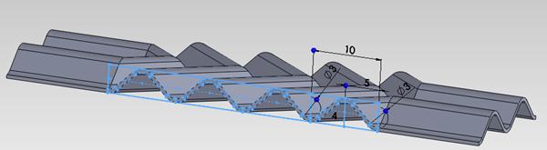
Figure 2. Geometric parameters corrugated channel
Computational fluid dynamics ANALISYS
Fluent software allows choosing one of the available turbulence models, as follows: RSM (Reynolds mediation), LES (large eddies simulation), DES (detached eddies simulation) model (k-ε) model (k-ω) [11, 12, 13].
For this study was used (k - ω) SST (Shear Stress Transport) turbulence model, because for this type of geometry must be modelled in detail both: flow areas near the wall plate and that witch are close to the axis of the current flow created between the plates. The model is a complex combination of the other two models (k - ω) and (k - ε), with a function that activates model (k - ω) in areas of wall and (k - ε) model in central areas, thus benefit from the advantages of the two models into one, [4].
Underlying equations for (k, ω) SST (Shear Stress Transport) turbulence model [14, 15] are the continuity equation (relation 1), the mass conservation equation (relation 2), the transport equation (relation 3), kinetic energy transport equation (relation 4) and the transport equation for turbulent dissipation rate (relation 5):
|
|
(1) |
|
|
(2) |

|
|
(3) |
|
|
(4) |
|
|
(5) |


where: u – fluid velocity, in [m/s]; ρ – fluid density, in [kg/m3]; p – fluid pressure, in [N/m2]; υ – cinematic viscosity, in [m2/s]; x, y, z - cartesian coordinate system is used; Gk - is the generation coefficient of turbulent kinetic energy due to gradients of medium velocity; Gω - represent the specific rate of dissipation for turbulent kinetic energy; Γk şi Γω represents the effective diffusion of k, respectively ω; Yk şi Yω are the effective difusion of k and ω; Dω - is a diffusion coefficient.
The mesh of the field studied, presented in Figure 3, was achieved with approximately 13.8 million tetrahedral elements for each model, being rare in the central areas of current flow and denser both in the narrowed flow channel and curvature areas.
|
|
a.) β = 30° |
|
|
b.) β = 45° |
|
Figure. 3. Mesh detail for interest domain |
|


Imposed boundary conditions were the same for both models studied so it was considered constant inlet temperature for both agents: for hot water at 80°C and for the secondary agent (cold water) 20°C. To simplify the model was considered that the primary agent (hot water) passes through the space formed between the two plates and the plates have secondary agent water temperature (cold water).
Results and discussion
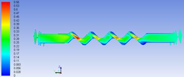
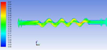
Velocity field shown in Figures 4 and 5 shows that speed vectors are mainly oriented throughout central axis of the flow channel, following the wave shape of the channel, and their intensity increases considerably both in narrowed channel areas and in areas of curvature drawing at maximum height. Vortex created in these areas lead to increasing the heat flux submitted to the secondary heat agent. Although the channel length that runs of these vortices is higher for the geometry with tilt angle β = 30°, so that the hot fluid stays longer in contact with the plate, velocity vectors still have more time to settle before leaving the flow channel, which slowing the turbulence effect on active plate height.
|
|
|
|
|
a.) |
b.) |
|
|
Figure 4. Velocity field in the middle section between the two plates a. β = 30°, b. β = 45°
|
||


|
|
a. β = 30° |
|
|
b. β = 45° |
|
Figure 5. Velocity field in longitudinal section between two plates |
|
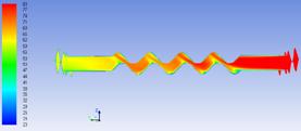
At the geometry with the tilt angle β = 45° is observed that the working fluid shows sudden changes in flow direction, causing change of velocity direction and forming more turbulent centres with a higher intensity of heat transfer that break the fluid in short areas, adding intensity to vortex created. Shorter corrugated channel length from centre to the edge of the plate does not allow stabilization of the velocity vector and involves an increase in flow velocity on plate active height.
|
|
|
|
|
a.) |
b.) |
|
|
Figure 6. Temperature field in the middle section between the two plates a. β = 30°, b. β = 45°
|
||
|
|
|
|
|
a.) |
b.) |
|
|
Figure 7. Temperature field in longitudinal section between two plates a. β = 30°, b. β = 45° |
||
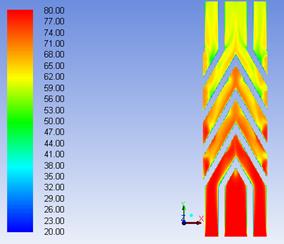
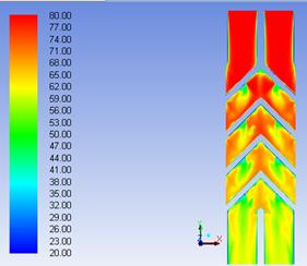

In Figures 6 and 7 is shown the temperature field in the liquid layer formed between two adjacent plates. This is presented in the middle section of the plate in the (x - y) plane (Figure 6) and in longitudinal section in Figure 7. For the model with β = 30° value of tilt angle the primary flow enters the space from the bottom, while the second model (β = 45°) hot fluid enters through the top. The main agent temperature at the entrance in flow area is 80°C (represented in red colour map). During heat flow mainly in active plate height, the fluid is cooled, succumbing heat to plate material. The best heat transfer was achieved for β = 45° model, where the working fluid was cooled from 80° C to about 56°C, so a difference of temperature of 24°C, while for β = 30° geometry, the final temperature of the fluid reach about 62°C so the cooling is only 18°C.
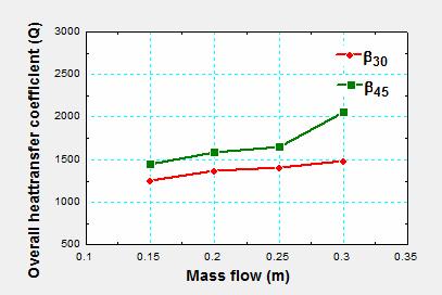
In figure 8 is represented the influence of mass flow and tilt angle on the overall heat transfer coefficient (k). According to the chart, for each model analysed, there is a proportional increase of overall heat transfer coefficient with increasing mass flow. The geometric model with the largest value of tilt angle submit the working fluid to more abrupt changes in the velocity and in flow direction, thus increasing the vortex and heat transfer.
|
|
|
Figure 8. Overall heat transfer coefficient (k) depending on the mass flow |
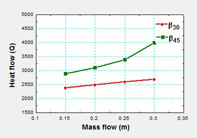
In Figure 9 is shown the influence of mass flow and tilt angle on the heat flow. Heat flow equation shows that it is directly proportional to the overall heat transfer coefficient, meaning that heat flow follows the same trend of increase with increasing of mass flow. This chart also shows that geometry with 45° value of tilt angle has the best results.
|
|
|
Figure 9. Heat flow variation depending on the mass flow |
Conclusions
This paper presents a CFD numerical study on plate type heat exchangers. For this study were design 2 models of plates with β = 30° value of tilt angles, and β = 45°. The plate geometry with the tilt angle higher than β = 45° creates a larger turbulent area in the interior of the channels created between two adjacent plates placed one normal and the other rotated with 180°, and the shorter length of these channels, favour’s the intensification of vortices on active plate height, while for plates with β = 30° value of tilt angle, channel length creates additional reassurance that lower intensity areas heat transfer. The intensity of heat transfer is distinguished both by turbulence created in the areas narrowed flow channel and channel curvature areas at maximum height (Figure 4) and the degree of cooling is the main heat about 24°C for β = 45° and for β = 30° to 18°C.
With increasing mass flow of hot fluid circulated through the channels, it is recorded also increase of overall heat transfer coefficient who have superior values for channel configuration at an angle of inclination β = 45° (Figure 6 and 7).
References
1. Plesa A., Grieb C. F., Nagi M., Utilaje termice. Schimbatoare de caldura cu placi, Cluj-Napoca, Mediamira, 2008
2. Zhu J., Zhang W., Optimization design of plate heat exchangers (PHE) for geothermal district heating systems, 2004, 33, p. 337-347.
3. Rush T.A., Newell T.A., Jacobi A.M., An experimental study of flow and heat transfer in sinusoidal wavy passages, Int. j. heat mass transfer, 1999, 42, p. 1545–1553.
4. Dwivedi A.K., Das K.S., Dynamics of plate heat exchangers subject to flow variations, Internatonal journal of heat and mass transfer, 2007, 50 (13–14), p. 2733–2743.
5. Durmus A., Benli H., Kurtbas I., Gul H., Investigation of heat transfer and pressure drop in plate heat exchangers having different surface profiles, International journal of heat and mass transfer, 2009, p. 1451–1457.
6. Fernandes C. S., Dias R.P., Jo˜ao N´obrega M., Jo˜ao M. M., Laminar flow in chevron-type plate heat exchangers: CFD analysis of tortuosity, shape factor and friction factor, Chemical engineering and processing, 2007, 46, p. 825–833.
7. Gherasim I., Galanis N., Nguyen C.T., Effects of smooth longitudinal passages and port configuration on the flow and thermal fields in a plate heat exchanger, applied thermal engineering, 2011, 31(17–18), p. 4113–4124.
8. Tsai Y.C., Liu F.B., Shen P.T., Investigations of the pressure drop and flow distribution in a chevron-type plate heat exchanger, International communications in heat and mass transfer, 2009, 36, p. 574–578.
9. Zhao Z.N. Effects of the corrugated inclination angle on heat transfer and resistance performances of plate heat exchangers, Petro-chemical equipment, 2001, 5, p. 2–3.
10. Giurgiu O. I., Bode F., Opruţa D. Study regarding the influence of the crimping angle on the performances of the heat exchangers, Experimental fluid mechanics, 2012, p. 209-303.
11. Salim M.S., Cheah S.C., Wall y+ Strategy for Dealing with Wall-bounded Tlrrbulent Flows, Proceedings of the international multi conference of engineers and computer scientists, March 18 – 20 2009, 2.
12. Kanaris A.G., Mouza, A.A., Paras, S.V., Flow and heat transfer in narrow channels with corrugated walls CFD code application, Chemical Engineering research and design, 2005, 83 (5 A), p. 460-468.
13. Pelletier O., Strömer F., Carlson A., CFD simulation of heat transfer in compact brazed plate heat exchangers, ASHRAE Transactions, 2005, 111(1), p.846-854.
14. Ansys 12.0 Theory Guide <-page 4.24 - 4.36.
15. Resiga R., Complemente de mecanica fluidelor si tehnici de solutionare numerica, Timisoara, Orizonturi Universitare, 1999