Mechanical properties of dual phase steel quenched in bitumen medium
Adeolu Adesoji ADEDIRAN1*, Sunday ARIBO2, Muhammed Olalekan Hakeem AMUDA3
1,2Department of Metallurgical and
3Department of Metallurgical and
E-mails: 1*dladesoji@yahoo.com; 2aribosunny@yahoo.com; 3mwalehakeem@yahoo.com
*Corresponding author, phone: 08032458545
Abstract
The mechanical properties of a dual phase steel treated in different intercritical windows and subjected to bitumen as the quenching medium was investigated. The viscosity of the quenchant was altered at several rate, the morphology of phases formed was characterized. Also, the quenched samples produced ferrite-martensite phases obtained at different intercritical windows. The tensile and hardness behaviour of the structures was examined; and the microstructures were characterized. It was observed that samples intercriticaly heat treated at 790°C and held for 60mins, bitumen quenched at 125°C, offers the highest impact toughness, while its counterpart at 730°C soaked for 30mins, bitumen quenched at 125°C offered the least impact toughness value. Sample intercriticaly treated at 790°C and held for 45mins in a 150°C quenching, offered the peak hardness factor. However, samples at 790°C held at 45mins and bitumen quenched at 150°C possessed relatively the best combination of tensile properties, hardness and impact energy. The water quenched samples at 790°C held for 60mins has the peak hardness value. The micrographs as well showed a uniformly distributed dual phase structure of ferrite and martensite at various volume fractions.
Keywords
Dual phase; Bitumen quenching; Intercritical temperature; Soaking time
Introduction
The structure of dual phase steel consists of ferritic matrix and islands of martensite. Martensite increase strength of basic material and ferritic matrix provide good plastic properties [1]. With combination of high strength, good ductility and reasonable yield strength, dual phase steels are ideal materials for automobile manufacturing [2, 3]. The interest originates from the demand for lighter, more fuel efficient vehicles and the fact that the dual phase steels combine superior ductility, with good tensile strength, and in this regard their properties are very similar to plain carbon steels [4, 5]. The ferrite matrix provides the ductility while the high strength particles provide strength. Besides these properties, other useful properties of these steels are low yield strength, continuous yielding behaviour, and highly uniform total elongation [6–9]. The mechanical properties of dual phase steels are affected by several factors, including; the volume fraction, the morphology of hard phase [10], and the ferrite grain size [11]. Alaneme [12] noted that properly determined treatment parameters can help provide duplex microstructures of ferrite and martensite of the right volume proportion that will yield a good combination of tensile and strength and ductility. Francisca et al. [13] observed that increasing the cooling rate and soaking time with low intercritical temperature eliminates/influences the microstructural banding in cold rolled dual phase steel. Also, Panda et al. [14] investigated that in the intercritical range, the formation of ferrite was observed more by quenching.
The present work examines the role of heat treatment parameters (intercritical temperature, soaking time/ temperature) and quenching parameters especially bitumen, on the mechanical properties of medium carbon dual phase steel.
Material and method
The materials utilized in this research include medium carbon low alloy (MCLA) steel (with chemical composition shown in Table 1), bitumen (quenchant), distilled water, emery cloth, and 2% nital as the etchant.
Table 1. Chemical composition of the MCLA steel
|
C |
Si |
Mn |
S |
Cr |
Ni |
Cu |
Fe |
|
0.389 |
0.182 |
0.980 |
0.030 |
0.111 |
0.135 |
0.368 |
balance |
Medium size lathe machine
The representative samples in figure 1a and b below were cut to sizes by a hacksaw and machined to the dimensions below on a medium size lathe machine, while Vernier calliper was used to check the dimensional accuracy.
Grinding /polishing machine
After machining, the samples were further subjected to grinding and polishing to obtain a mirror like image, and then dried with a hand dryer before subjecting it to metallographic examination.
NDJ-5S Digital Viscometer
The rheology nature of quenchant was determined through the use of viscometer; the quenchant was first heated below the flash point of the quenchant. A heating element was use and pyrometer used to monitor the temperature.
Algorithm used in the research
The algorithm used in this research is presented bellow:
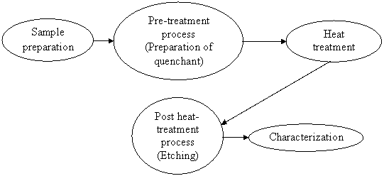
Sample preparation
Medium carbon steel was machined to tensile specimen configuration of gauge length 30mm, diameter 6mm and chamfered at an angle 45° (Figure 1a), while a notched impact specimen was machined to a length of 60mm, diameter 8mm, depth of 2mm and notch angle of 45° (Figure 1b) the impact test. Samples were also machined to 8mm diameter and 10mm length for the hardness tests and microstructural examination.
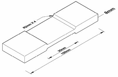
Figure 1a. Sample specimen chamfered at an angle 45°
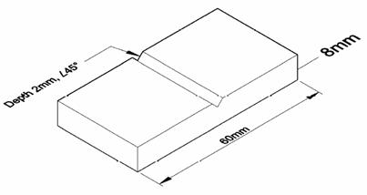
Figure 1b. Sample specimen notch at angle of 45°
Intercritical treatment
Since the metallurgical pre-history of the supplied material is unknown; the machined specimens were initially normalized at 810°C for 1 hour in a muffle furnace and then air cooled, for structural re-adjustment, re-conditioning of the phases and to induce homogeneity in the structure. Intercritical treatment was thereafter carried out on the remaining samples at 730°C, 760°C, 790°C temperatures over a holding times of 30, 45 and 60 minutes at each temperature. At the end of every stage, the samples were quenched in distilled water and bitumen at 100°C, 125°C and 150°C.
Hardness measurements
The hardness of the treated specimens was evaluated using a Brinell hardness (Gunt micro hardness tester). Prior to testing, the steel specimens were grinded and polished to obtain a smooth surface finish. A direct load of 20 kN was thereafter applied on the specimen for a dwell time of 10 seconds and the hardness readings evaluated following standard procedures. Multiple hardness tests were performed on each sample and the average value taken as a measure of the hardness of the specimen.
Tensile testing
Room temperature uniaxial tension tests were performed on round tensile samples machined from the steel sample with dimensions of 6mm diameter and 30mm gauge length. An Instron-universal tensile testing machine following standard test procedures in accordance with the ASTM E8M - 91 standards was utilized. The samples were tested at a nominal strain rate of 10–3/s until failure. Multi tests were performed for each test condition to ensure reliability of the data generated. The tensile properties evaluated from the stress-strain curves developed from the tension test are - the ultimate tensile strength (σu), the yield strength (σy), and the strain to fracture (εf).
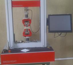
Figure 2. Instron-universal tensile testing machine (M500-50AT)
Results and discussion
Microstructural examination
The microstructural investigation was performed using optical metallurgical microscope. The specimen for the microscopy were grinded using a series of emery paper of grits sizes ranging from 340µm-1200µm, it was further polished using an ultra fine polishing cloth, its effectiveness was enhanced using polycrystalline diamond suspension of particle size 3µm with ethanol solvent. The specimen was chemically etched by swabbing following a standard information guide before microstructural examination was performed using simple metallurgical microscope.
Table 2. Bitumen quenched samples
|
S/N |
Factor1: |
Factor 2 |
Factor 3 |
Response 1 |
Response 2 |
Response 3 |
|
|
Soaking Temperature |
Soaking Time |
Temp of |
Hardness |
Yield Strength |
Impact Toughness |
|
|
(°C) |
(min) |
Quenchant (°C) |
(HRB) |
(MPa) |
(J) |
|
P |
730 |
60 |
125 |
200.55 |
532.14 |
p |
|
E |
760 |
30 |
100 |
293.55 |
610.41 |
52.32 |
|
L |
790 |
45 |
100 |
229.23 |
554.36 |
41.82 |
|
C |
760 |
60 |
100 |
226.04 |
609.82 |
54.23 |
|
V |
730 |
45 |
150 |
260.6 |
542.23 |
44.74 |
|
S |
730 |
30 |
125 |
122.06 |
531.23 |
24.41 |
|
O |
790 |
60 |
125 |
217.82 |
572.24 |
55.59 |
|
A |
760 |
45 |
125 |
251.90 |
582.37 |
40.67 |
|
J |
790 |
30 |
125 |
305.75 |
564.46 |
50.17 |
|
K |
790 |
45 |
150 |
381.97 |
594.96 |
48.82 |
|
B |
760 |
60 |
150 |
251.90 |
522.46 |
40.67 |
|
D |
760 |
30 |
150 |
237.58 |
558.34 |
42.03 |
|
Q |
730 |
45 |
100 |
291.14 |
529.49 |
27.12 |
Table 2 shows a representative values of the samples quenched under bitumen media. The parameters such as soaking temperature, soaking time and temperature of quenchant are represented as factor 1, factor 2 and factor 3 respectively. While the mechanical properties such as hardness, yield strength and impact toughness are presented as response 1, response 2 and response 3 respectively.
In Table 3 however, there are three responses; representative of the mechanical properties, while the factors are soaking temperature represented by factor 1 and factor 2 representing the soaking time.
Table 3. Water quenched samples
|
S/N |
Factor 1 |
Factor 2 |
Response 1 |
Response 2 |
Response 3 |
|
|
A:Soaking Temp(°C) |
B:Soaking Time(min) |
Impact (J) |
Yield Strength(MPa) |
Hardness (HRB) |
|
I |
730 |
30 |
14.24 |
563.39 |
153.5 |
|
N |
730 |
60 |
14.92 |
518.98 |
182 |
|
F |
730 |
45 |
13.56 |
678.18 |
309.06 |
|
G |
760 |
30 |
12.2 |
572.21 |
248.39 |
|
U |
760 |
45 |
11.53 |
559.54 |
233.9 |
|
R |
760 |
60 |
13.56 |
538.14 |
358.89 |
|
H |
790 |
60 |
12.2 |
542.58 |
488.24 |
|
M |
790 |
45 |
13.56 |
548.32 |
432.49 |
|
T |
790 |
30 |
9.49 |
532.21 |
118.73 |
|
Control(X) |
|
|
24.41 |
505.52 |
370.77 |
Results obtained are presented in Figures 3-13, water quenched samples (wqs) were placed parallel to bitumen quenched samples (bqs), Figure 11 (a – o), Tables 2 and 3. The chemical composition of the material used is shown in Table 1.
|
|
|
|
Figure 3.Impact against soaking time for water quenched samples (wqs) |
Figure 4. Impact against quenching temperature (bqs) |
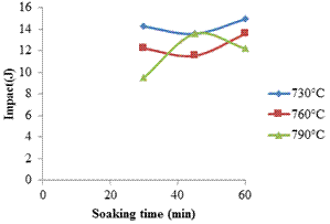
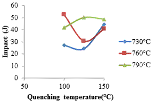
Figure 3 shows the intercritical windows (730°C, 760°C and 790°C) the impact behaviour is represented and Figure 4 shows the impact energy against the quenching temperature for the quenchant. The effect of quenching temperature on the impact energy is represented here.
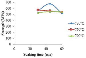
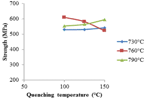
In Figure 5 a representative of the strength of the material against the holding time is presented here and in Figure 6 the influence of quenching temperature of the quenchant on the strength of the material is represented.
In Figure 7 the hardness property of the material under examination with respect to the holding time especially the water quenched samples are highlighted. Figure 8 shows the effect of hardness on quenching temperature for bitumen quenched medium within the intercritical window of 730°C, 760°C and 790°C.
|
|
|
|
Figure 5. Yield Strength against soaking time (wqs) |
Figure 6. Yield Strength against quenching temperature (bqs) |
|
|
|
|
Figure 7. Hardness against soaking time (wqs) |
Figure 8. Hardness against quenching temperature (bqs) |
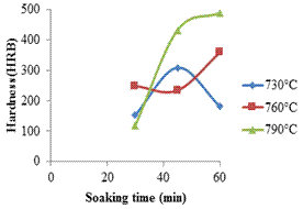
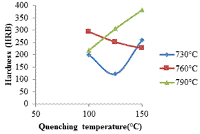
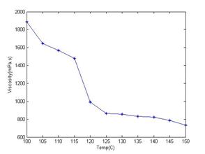
Figure 9. Viscosity against quenchant temperature
Figure 9 shows the viscosity (Mpa) as against the quenchant temperature The quenchant temperature are carefully selected just below the flash point of the quenchant.
|
|
|
|
Figure 10. True stress against true strain for samples U, C, D, I, E |
Figure 11. True stress against true strain for samples A, B, O, P, Q |
|
|
|
|
Figure 12. True stress against true strain for samples X, S, J, L, K, F |
Figure 13. True stress against true strain for samples R, M, V, T, H, G |
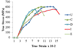
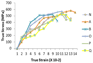
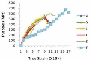
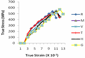
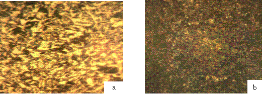
Figure 14.a. as received; b. 730°C, held for 30min and water quenched X400
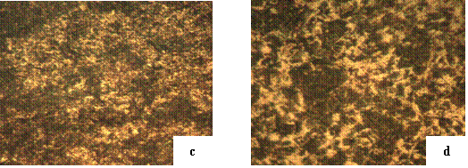
Figure 14.c. 730°C, held for 45min and water quenched; d. 730°C, held for 45min and bitumen quenched at 100°C X400
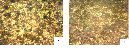
Figure 14.e. 760°C, held for 30min and bitumen quenched at 100°C; f. 760°C, held for 45min and bitumen quenched at 125°C X400
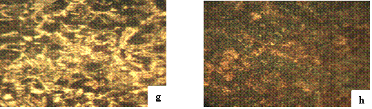
Figure 14.g. 730°C, held for 60min and bitumen quenched at 150°C; h.730°C, held for 60min and water quenched X400
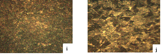
Figure 14.i. 730°C, held for 30min and water quenched; j.790°C, held for 45min and bitumen quenched at 150°C X400
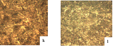
Figure 14.k. 790°C, held for 60min and bitumen quenched at 125°C; l. 760°C, held for 45min and bitumen quenched at 125°C X 400
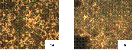
Figure 14.m. 730°C, held for 45min and bitumen quenched at 100°C; n. 760°C, held for 60min and water quenched X 400
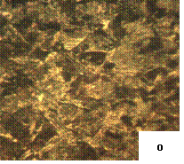
Figure 14.o. 790°C, held for 45min and bitumen quenched at 100°C X 400
Influence of intercritical temperatures and holding time on the hardness/impact
The purpose of impact test is to measure resistance of materials to high rate of loading. It is usually thought of in terms of two objects striking each other at elevated speeds. A part or materials ability to resist impact is one of the determining factors in the service life of a material. The ability to quantify this property is a great advantage in product liability and safety. Figure 8 shows the variation of hardness with soaking time for water quenched sample (wqs), the peak hardness value of 488.24 HRB is observed at 790°C soak for 60 min. Lower intercritical temperatures favours lower hardness value of 153.5 HRB. However, higher intercritical temperature and higher quenching temperature increases the hardness value to 381.97 HRB for bitumen quenched samples. An observation from the graph shows a significant rise in hardness signifying the formation of increased amount of martensite, especially for sample k and j; a decrease in hardness values in sample j could be as a result of the decomposition of cementite [16, 21], spheroidization and primary recrystallization which are dominant at this stage [19]. This competes and occurs simultaneously with other transformations taking place. It was also observed that the hardness values of the developed dual phase structures has a direct relation with the volume fraction of martensite with 760°C bitumen quenched at 100°C having the highest strength value of 610.41MPa, though its impact energy as well, witness a significance increase. The sample intercritical treated at 790°C and quenched at 125°C has the highest impact resistance, while the sample intercritical treated at 730°C and quenched at 100°C has the least energy of 27.12J. When quenched at lower temperature, there could be less carbon and alloying elements dissolved in the austenite, and the saturated carbon and alloying elements in martensite were less after quenching as well. This might have led to lower hardness to the material.
Influence of intercritical temperatures and holding time on the microstructures
Figure 14a shows the micrograph of the normalized structure that produced pearlite which is an equilibrium structure that can scarcely undergo further phase change during the intercritical treatment until a prolonged heating at the intercritical temperature region coalescence of the cementite in the pearlite structure [18] leading to the commencement of (α + γ) transformation from the coalescence of the cementite in the initial microstructure. Figures 14b – o are micrographs showing the microstructural evolution that occurs during intercritical treatment and variation of quenching temperature. It confirms that intercritical treatment develops microstructures that exhibited micro-duplex features consisting of soft and ductile ferritic (grey) zone combined with hard and brittle martensitic (dark – formerly austenitic) zone. A homogenized structure of ferrite and martensite is achieved with much longer soaking time at various phase volume percentages [17, 20]. When the quenching temperature increases, the amount of carbon and alloying elements dissolved in the matrix increase and the solution strengthening of matrix improves which promotes the increase of the tensile strength.
Influence of intercritical temperatures and holding time on the mechanical behaviour
Figures 10-13 show the true stress – strain for the dual phase structure produced at 730°C, 760°C and 790°C over different holding times of 30, 45 and 60 minutes at each temperature and varying quenching temperatures. The sample labelled X, is a representative of the as-received with a yield strength of 505.52 MPa shown in table 3. It was observed that the dual phase structures exhibited continuous yielding despite the large volume fractions of martensite; it is also observed to exhibit higher ultimate tensile strength (UTS). The trends observed were found to be in conformity with finding reported in literatures [15, 20]. Also, the brittle nature reduces as the intercritical temperature increases; this was in line with Sharma et al. [22]. The lower limit of the intercritical temperature when water quenched, possesses high yield strength when compared to the bitumen quenched at the same temperature. When compared with samples at the highest intercritical temperatures witnessed the highest hardness value of 488.24 HRB and 432.49 HRB at 790°C held for 60 min and 790°C held at 45min respectively.
Conclusions
In the present research work, the mechanical properties and the microstructures behaviour of 0.4%C bitumen quenched dual phase steel was studied. From the results, it was observed that 0.4%C steel when subjected to intercritical treatment at 730°C, 760°C and 790°C and bitumen quenched, resulted in a significant increase in the tensile and hardness properties of the developed dual phase steel in comparison to the normalized specimen. It was observed that samples intercriticaly heat treated at 790°C and held at 60 min-bitumen quenched at 125°C offers the highest impact toughness, while its counterpart at 730°C soak at 30 min and bitumen quenched at 125°C offers the least impact toughness value. Sample intercriticaly treated at 790°C and held for 45 min in a 150°C quenchant, offers the highest hardness factor. However, samples at 790°C held at 45 min-bitumen quenched at 150°C possess relatively the best combination of tensile properties, hardness and impact energy. The peak value in hardness was observed at 790°C held at 60 min. The micrographs as well showed a uniformly distributed dual phase structure of ferrite and martensite at various volume fractions. The higher the intercritical temperature and soaking time, the higher the hardness value for both the water quenched and bitumen quenched samples.
References
1. Buriková K., Rosenberg G., Quantification of microstructural parameter ferritic-martensite dual phase steel by image analysis, Metal, 2009, 5, p. 19-21.
2. Lis J, Lis A. K, Kolan C, Processing and properties of C-Mn steel with dual phase structure, Journal of Materials Processing Technology, 2005, 162-163, p. 350-354.
3. Davies R. G, Influence of martensite composition and content on the properties of dual phase steel, Metallurgical Transactions A, 1978, 94, p. 671-679.
4. Bag A., Ray K. K., Dwarakadasa E. S, Influence of martensite content and morphology on tensile and impact properties of high-martensite dual-phase steels, Metallurgical and Materials Transactions-A (Warrendale); 1999, 30(5), p. 1193-1202.
5. Tavares S. S, Pedroza P. D, Teodosio J. R., Gurova T, Mechanical properties of a quenched and tempered dual phase steels, Scripta Materialia, 1999, 40, p. 887-892.
6. Hillis D. J., Llewellyn D. T., Evans P. J., Rapid annealing of dual-phase steels, Journal of Iron-Making Steelmaking, 1998, 25(1), p. 47-54.
7. Suh D.W, Kwon D.I, Lee S.H, Kim N.J, Orientation dependence of microfracture behaviour in dual-phase high-strength low-alloy steel, Metallurgical and Materials Transaction A,1997,28(2) pp 504-509.
8. Hansen S. S., Pradhan R. R., Fundamentals of dual phase steels, Proceedings of the Metallurgical Society of AIME, Warrendale, USA, 1980, pp. 113-140.
9. Ahmad E., Manzoor T., Ali K. L., Akhter J. I., Effect of microvoid formation on the tensile properties of dual-phase steel, Journal of Materials Engineering and Performance, 2000, 9(3), p. 306-310.
10. Erdogan M., Priestner R., Effect of martensite content, its dispersion, and epitaxial ferrite content on Bauschinger behaviour of dual phase steel, Journal of Materials Science Technology, 2002, 18, p. 369-376.
11. Sun S., Pugh M., Properties of thermo mechanically processed dual phase steel containing fibrous martensite; Material Science engineering A, 2002, 335, p. 298-308.
12. Alaneme K. K., Phase transformation studies of a low alloy steel in the (α-γ) phase region, Materials Research, 2010, 13(1), p. 113-117.
13. Francisca G. C., Andrea G. J., Carlos C., Carlos G. A., Evolution of microstructural banding during the manufacturing process of dual phase steel, Materials Transactions 2006, 47(9), p. 2269-2276.
14. Panda A. K., Ray P. K., Ganguly R. I., Effect of thermomechanical treatment parameters on mechanical properties of duplex ferrite-martensite structure in dual phase steel, Material Science and Technology, 2000, 16, p. 648-656.
15. Mohammad R. A., Fardin N., Seyed E. H. A., Hasan R., Effect of intercritical heat treatment for long times on the mechanical properties of AISI 4340 steel, Materials and Energy Research Center, 2009, p. 14155-4777.
16. Holm E. A., Miodownik M. A., Rollet A. D., On abnormal subgrain growth and the origin of recrystallization nuclei, Acta Materialia, 2003, p. 2701-2716.
17. Gorelik S. S., Recrystallization in metals and alloys, 1981, 2nd Ed., Moscow: Mir Publishers.
18. Ghosh S. K., Bandyopadhyay N. R., Chattopadhyay P. P., Effects of finish rolling temperature on the microstructures and mechanical properties of as hot rolled Cu-added Ti, B micro-alloyed dual phase steels, Journal of the Institution of Engineers (I) 2004, 85, p. 41-48.
19. Dongsheng L., Matthias M., Warren P., Microstructure model for a dual-phase steel, Material Science Forum, 2007, 539-543, p. 4391-4396.
20. Alaneme K. K., Influence of tempered microstructures on the transformation behaviour of cold deformed and intercritically annealed medium carbon low alloy steel, Material Research, 2010, p. 1516-1518.
21.
Alaneme K. K., Kamma C.
M., Phase transformation studies of a low alloy steel in the (α+![]() ) phase region, Material Research, 2010, p. 1439-1443.
) phase region, Material Research, 2010, p. 1439-1443.
22. Sharma S. S., Prabhu P. R., Rajagopal C., Thermal treatments and characteristics study on unalloyed structural (AISI 1140) steel, World Academy of Science, Engineering and Technology, 2010, 4, p. 667-672.