Design and implementation of microcontroller-based automatic sequence counting and switching system
Joshua ABOLARINWA*, Abubakar ISAH
Department of Telecommunications Engineering, Federal University of Technology, Minna, Nigeria
E-mails: *abolarinwajoshua@yahoo.co.uk, scholarmails@aol.com
*Corresponding author, phone: +2348060109483
Abstract
Technological advancement and its influence on human being have been on the increase in recent time. Major areas of such influence, include monitoring and control activities. In order to keep track of human movement in and out of a particular building, there is the need for an automatic counting system. Therefore, in this paper, we present the design and implementation of a microcontroller-based automatic sequence counting and switching system. This system was designed and developed to save cost, time, energy, and to achieve seamless control in the event of switching on or off of electrical appliances within a building. Top-down modular design approach was used in conjunction with the versatility of microcontroller. The system is able to monitor, sequentially count the number of entry and exit of people through an entrance, afterwards, automatically control any electrical device connected to it. From various tests and measurements obtained, there are comparative benefits derived from the deployment of this system in terms of simplicity and accuracy over similar system that is not microcontroller-based. Therefore, this system can be deployed at commercial quantity with wide range of applications in homes, offices and other public places.
Keywords
Monitoring unit; Automatic sequence; Counting system; Switching system; Microcontroller unit
Introduction
Keeping track of events or activities has been a major concern to mankind both in medieval time and in modern era. The ability to seamlessly control or operate devices has posed great challenge until recent time when electronic technology has made this a lot easier. According to [1], for centuries, mathematics was considered to be the science of numbers, magnitudes, and forms. For that reason, those who seek early examples of mathematical activity will point to archaeological remnants that reflect human awareness of operations on numbers, counting, or geometric patterns and shapes.
Automatic sequence counting and switching system is a multifunctional system that performs dual functions of sequence counting of human entry and exit at an entrance, and at the same time switches any electrical appliance connected to it. This multifunctional capability stems from the use of programmable very large scale integrated circuit (VLSIC) commonly called microcontrollers (MC) alongside other integrated circuit (IC) elements. In order to apply the versatility of MC, authors in [2] proposed remote monitoring through mobile phone. Based on the command sent via the mobile phone, the MC performs a particular task.
In their work, authors in [3] discussed several problems associated with the design and implementation of home automation systems. Problems such as, compatibility, robustness, etc were discussed. Possible solutions through the use of various network technologies were also discussed. However, no mention was made of the use of top-down modular design approach. [4] proposed a low-cost and flexible internet-based wireless home automation system. However, problems of range and power failure were the bane of this system. The authors in [5] proposed a mobile-based home automation system that consists of a mobile phone with Java capabilities, a cellular modem, and a home server. The home appliances are controlled by the home server, which operates according to the user command received from the mobile device. Application of VLSIC an IC in the implementation of MC based system is the main focus of [6]. Various electronic components characteristics and mode of operation are explained together with the internal circuitry of the components.
Myers, et al in [7] projected that the future home network will have ubiquitous embedded computation with an increasing number of appliances having wireless communication. Hence, with this arise the need for cooperation between sequential counting and automatic switching operation. Taking this further, authors in [8] suggested the use of speech to interact remotely with the home appliances to perform a particular action on behalf of the user. The approach is aimed at helping people with disability to perform real-life operations at home by directing appliances through speech. Voice separation strategy is selected to take appropriate decision by speech recognition. In [9], the authors suggested a design strategy for better notification system and support collaborative activity.
In [10], the author looked at the possibility of having ubiquitous access to many devices within a building at the simultaneously. This is aimed at saving significant amount of time, as well increase security in a building. For the purpose of practical demonstration authors in [11] investigated how handheld devices and speech can be used to improve the interfaces to home and office appliances. This was achieved by the use of the approach the authors called personal universal controller (PUC). The PUC is a remote control device for improving the interfaces to complex appliances. It is different the common universal controller because it is self-programming.
However, regardless of the extensive work done in literature on automation, less attention has been given to combining sequential counting with switching operation of electronic system seamlessly. The objective of this work is to design and develop a system that both count human entry and exit in a particular building and seamlessly switch and appliance within the building. This will help to same time, energy and cost. In order to achieve this objective, a top-down modular design approach was used. This is for the purpose of design simplification and easy implementation. Among others, the system developed finds wide range of applications in both residential building and public places. it can also be used as sequence counter to monitor the number of inflow and outflow per time. It equally finds application as a switching device.
Materials and method
The block diagram of the entire system design, with each block representing a module and the interconnection of various modules is shown in Figure 1.
The system comprises of a regulated 5V power supply, an infrared (IF) body sensor (i.e transmitter and receiver IF), 8-bit microcontroller, a relay and seven segment display as shown in Figure 1.
Figure 1. Block diagram of automatic sequence counting and switching system
Design and operation overview
The system is powered by regulated 5V DC power supply. The motion sensing unit consists of IF transmitter and receiver system, which detects human body movement between the transmitter and the receiver and initiates a count (up or down) depending on whether it is entry or exit. The system controller unit is made up of a microcontroller and analog to digital converter (ADC). Other associated circuitry and program code coordinates and controls the input from the motion detector and the output through the relay to either the digital display unit or the load.
The display unit shows the number of count (up or down) based on the processed information at the controller unit. During the down count, which signifies exit, upon zero count, that is, at the exit of the last person the switching operation is activated. Upon activation, any load connected to the system is trigger.
Motion sensor unit
The motion sensor unit works on the principle of infrared transmission and detection. It comprises of two identical modules: an infrared transmitter and an infrared receiver.
An IR radiation-based-motion-detection front-end passage was incorporated to monitor entry and exit of human body. To achieve this, a 38kHz oscillator was used to generate IF energy, which is beamed in the same direction towards the receiver module. This is shown in Figure 2.


Figure 2. Infrared emitter wired as an astable multivibrator
Due to obstruction by human body passing between the transmitter and receiver, the radiated energy from the transmitter is barred from reaching the receiver. To achieve this the IF receiver circuit is configured in monostable mode, while the transmitter is configured in astable mode.
The IR transmitter
A 50.5% duty cycle IF transmitter, which comprises of an infrared emitter light emitting diode (LED) wired around a NE555-timer IC configured in astable mode. The circuit connection of the astable multivibrator is shown in Figure 2. The astable circuit produces digital waveforms with a share transitions between HIGH 5V and LOW 0V. The circuit is termed astable because it is not stable in any of the two states. The output continuously changes between LOW and HIGH.
Design calculations
According to [12] and [13], the generator frequency can be obtained when operating as astable oscillator as follows:
|
Tm = 0.693(RA+RB)C |
(1) |
|
Ts = 0.693(RB)C |
(2) |
where Tm is mark time (charging of capacitor through resistors RA and RB) and Ts is space time (discharging of capacitor through RB). Therefore, time period T is,
|
T = Tm + Ts T = 0.693(RA+RB)C |
(3) |
where the frequency F is,
|
F = 1/T F = 1/[0.693(RA+RB)C] |
(4) |
Therefore,
|
F = 1.443/[(RA+2RB)C] |
(5) |
These parameters are shown in Figure 2 as:
RA is resistance in Kilo ohms (KΩ) between pin 8 and pin 7;
RB is variable resistance in KΩ between pin 7 and pin 6;
C is capacitance in Pico farad (pf) between pin 1 and pin 6;
F is frequency in Hertz (Hz).
RB is adjusted to obtain a precise frequency of 38kHz. Therefore, the value of adjustable resistor is thus,
|
RB = 1.442/2fc - 0.5RA |
(6) |
where fc = 38 KHz, RA = 1KΩ, C = 0.001μF and RB = 18KΩ
But, for this design, a value of 18kΩ variable resistor was used so as to have a regular generation of beam.
The astable oscillator drives the IR emitter through a limiting resistor 100Ω.
|
I = V/R |
(7) |
|
I = (V - VLED)/R |
(8) |
where, I represent the electric current, V is the voltage drop across the resistor R, VLED = 1.2V is the voltage drop across the LED
|
I = (5 - 1.2)/100 = 38mA |
(9) |
Therefore, the peak current I = 38mA.
The IR detector (receiver)
The transmitted IR was detected by an IR sensor with part number TSOP1738. It consists of three terminals wired around the pins of an NE555 timer configured as a monostable multivibrator to generate a pulse of approximately 50cycles (0.5Hz) when triggered [14]. The connection is shown in Figure 3.

Figure 3. Infrared (IR) detector circuit wired as monostable multivibrator
The resistor-current (RC) component configured as monostable generates an output when the voltage of pin 2 falls below 1/3 of the source voltage VS. The input trigger is coupled into pin 2 of the NE555 timer through a 0.1μF capacitor to generate a short pin voltage when the output of the sensor goes LOW.
The output pin 1 of the sensor is HIGH in the absence of an IR signal, but goes LOW when an IR signal is detected. When no IR is detected by TSOP1738, the NE555-timer trigger off the voltage on pin 2 below 1/3VS and this causes pin 3 of the NE555-timer to get HIGH for a time period of 2 seconds as desired.
The output HIGH switches NPN-transistor is shown in Figure 3. This output interrupts the controller and this causes the system either to increment the inflow count via P 3.3 of the microcontroller or decrement the outflow count via P 3.2 of the microcontroller.
The sensing part implements the use of passive infrared sensor (PIR). The PIR sensor detects motion of an infrared emitting source usually a human body temperature above absolute zero (-273.15°C to 112.67°C). The sequence counting is achieved using counter logic circuit. The counter used is a combinational logic flip-flip together with analogue to digital converter (ADC) integrated circuit.
Multiplexed display unit
The visual display unit of this design comprises of a common anode seven segment light emitting diode (LED) display. The rapid-switching technique is done to reduce the number of separate decoder-driver for each digit display. Multiplexing allows a common path to be used for displaying numerous data.
In the multiplex mode, all digits to be multiplexed are connected in parallel with common segment tied together. The display of the digits is controlled by software program.
The 2SA1015GR transistor is PNP silicon transistor used as in anode driver mode to either switch ON or OFF LED display depending on which of the connected pin of the microcontroller is activated by the software implementation. The circuit connection of microcontroller interfaced to the display unit is shown in Figure 4.
The turning ON of a desired digit for a brief period of time and then OFF while other digits are completely OFF is periodically done at 50Hz, a frequency the eyes cannot perceive, but see it as a continuously lit display. The individual digit position is controlled by transistors Q1, Q2 and Q3 as illustrated in Figure 4.
Figure 4. Multiplexed display interfaced with AT89C51 microcontroller IC
Design calculation
100Ω current limiting resistor was placed in series with each segment. To calculate the peak current through a single segment display IP, where, continuous forward current for the LED, ID = 10mA. For the 3 digits to display on the LED:
|
IP = 3ID = 30mA |
(10) |
To calculate for the total peak current for the multiplex display,
|
IC = 7IP = 7∙30mA = 210mA |
(11) |
The 2SA1015GR transistor has a peak collector current IC of 150mA. This implies that the choice of this transistor I within the range.
The base current IB,
|
IB = IC/β = (210∙10-3)/200 = 1.05mA |
(12) |
where IC = 210mA, β (gain of amplifier) = 200
|
RB = VCC - VBE/IB RB = (5-0.7)/(1.05∙10-3) = 4.1kΩ visual |
(13) |
where VBE = 0.7V is the base/emitter voltage, RB is the base resistor, and VCC is the common collector voltage. A dimmed visual display was notice with a value of 4.1Ω. For sufficient brightness to be achieved, the calculated value of RB was reduced by a factor of 4, so the value of RB used is 1KΩ.
The operator interface unit
This unit is made up of input preset switches normally open, single-pole buttons, which were connected to some pins of port 3 of the microcontroller for preset and reset. These enable the user to preset number of occupants at will. For instance, a known number of occupants in a hall can be preset on the display at the power on of the system. For effective design of this unit, the keys were grounded, so that any key pressed will increment its value (i.e hundred, tens, units) instead of starting from “000”. The reset switch resets all displayed values to zero as shown in Figure 5.
Relay switch unit
For this unit, a 6V, 10A relay was incorporated to trigger load connected to the system. This depends on the occupancy level, that is, the number of counts. This was achieved through the differential count (entry and exit) of the microcontroller which takes place in the RAM register.
When the differential count is zero (occupancy level is zero), no current flow through the base of the transistor and as a result de-energize the relay which equally affect the load connected across it. Immediately there is an entry, the relay is energized through the base current of the PNP transistor which put the connected load in ON-state as illustrated in Figure 5. The load could be bulb, fan or any other electrical appliance. But for the purpose of testing, a 60W tungsten bulb was used. The base current of the transistor is controlled by the microcontroller via P3.7 as shown in Figure 5.
The diode with part number IN5392 placed across the relay coil is meant to prevent damage of the circuit due to back electromotive force (emf), and provide an alternative path for the emf spark generated when the relay is switched off.
Figure 5. Relay alternating current (AC) load switch
Design calculation
The relay has a coil resistance of 400Ω at 6V, 10W rating. To calculate the base transistor resistance RB;
|
IC = V/Rr IC = 6/400 = 15mA |
(14) |
where IC is transistor collector current, Rr is relay coil resistance, VBE is emitter-base voltage, V is supply voltage.
With transistor gain of 200,
|
IB = IC/β = (15∙10-3)/200 = 7.5∙10-5A |
(15) |
Therefore,
|
RB = VCC - VBE/IB = (5-0.7)/(7.5∙10-5) = 5.7KΩ |
(16) |
For this design a resistance of 50kΩ was used for these for the following reasons:
i. For worst operation voltage, the relay must operate down to 3.5V.
ii. A reduced supply of 5V powered the relay instead of 6V specified by the manufacturer.
Microcontroller unit
The microcontroller used for this design is an Atmel AT89C51 8-bit microcontroller [15]. It has a flash memory capacity of 4 kilobytes erasable and programmable read only memory (EPROM), 32 input/out lines, two 16-bit timers/counters, 128 byte of RAM, interrupt, serial port (on chip peripheral) in a continuous function state when the central processing unit (CPU) is in a state of rest (asleep). It has 40 pins configuration for interfacing [15].
Oscillator characteristics
Crystal C1 and Crystal C2 are the input and output respectively of an inverting amplifier which can be configured for use as an on-chip oscillator. A quartz crystal oscillator was used in the design to give external clock signal.
A single instruction cycle is executed for every 12 clock cycle of 8051 instruction set. So for 8051 clock at 12MHz, the instruction cycle time:
|
Instruction cycle time = 12 clock cycle/(12∙106cycle/sec) |
(17) |
So for every execution of a single instruction cycle takes 1µs.

Figure 6. Oscillator configuration of AT89C51
System software
The control software was introduced in this design to ease development and hardware limitations. The software for this system is written in low level assembly language. The functionality of the system and conditions to be implemented were first developed into a pseudo codes. The pseudo codes were later transformed into the assembly codes which were burnt into microcontroller using an EPROM programmer and a Progstudio 6.0 assembler. This is illustrated in Figure 7 and 8.
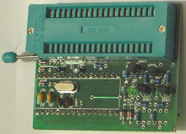
Figure 7. EPROM programmer electronic circuit board
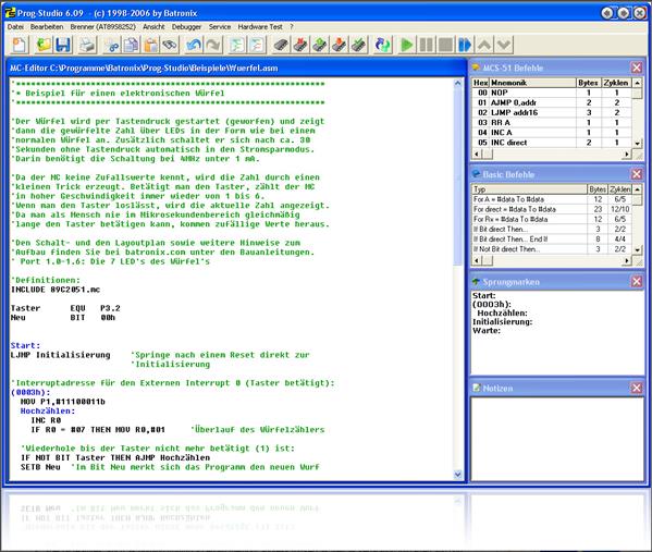
Figure 8. BATRONIX Prog-studio 6.0 assembler
Measurement and evaluation of performance
Various components were tested to know their manufacturer's ratings. Then the circuit for each module were constructed on a breadboard and tested to ensure they function according to design. Currents and voltages were measured at various points in the circuit. Soft simulation was used to test the microcontroller unit of the system.
The program for the microcontroller was debugged and simulated with the help of AVR studio 4 integrated development environments (IDE) software. This provide source file editor, chip simulator and interface for AVR 8-bit RICS family of microcontroller. The syntax errors were corrected in assembler Hex file editor. This is shown in Figure 9.
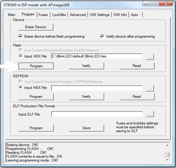
Figure 9. AVR Studio 4 working environment
The frequency of oscillator of the 555 timer (transmitter and receiver) was adjusted to 38KHz to suit time delay of the design interrupt.
The display unit gave the corresponding number of people that were made to pass through the system and it equally controlled (on and off) of the 60W tungsten bulb connected through the load to the switch. The measurement summary can be seen in Table 1.
Table 1. Variation of rated voltage values with measured values for various components
|
Unit |
Components |
Rated voltage (V) |
Measured voltage (V) |
Measured current (A) |
|
Power supply |
Transformer |
12 |
11.2 |
0.5 |
|
Rectifier |
9 |
7.2 |
|
|
|
Smoothening capacitor |
25 |
25 |
|
|
|
Voltage regulator |
5 |
4.8 |
0.5 |
|
|
Sensor |
555 timer |
5 |
4.9 |
0.00224 |
|
Threshold |
3.33 |
3.26 |
- |
|
|
Trigger |
1.67 |
1.6 |
- |
|
|
Display unit |
25A1015GR PNP Transistor 7-segment digit display |
5.0
|
4.75 2 |
0.15 0.0001 |
|
Load switch unit |
Relay |
6 |
5 |
10 |
The results obtained are approximately equivalent to the expected values. The slight differences are due to fluctuations in AC supply, and other environmental factors like temperature and light illumination.
Conclusion
With the use of top-down modular design approach, we are able to achieve a simple, cost effective and efficient system that can function as a control unit for electrical electronic devices in a building. Considering the results obtained during testing operation, this system has the potential of overcoming complexity associated with other systems that are not based on modular design method.
References
1. Boyer C. B., Merzbach U. C., A history of mathematics, John Wiley and Sons, 2011.
2. Jawarkar N. P., Ahmed V., Ladhake S. A., Thakare R. D., Micro-controller based Remote Monitoring using Mobile through Spoken Commands, Journal of Networks, 2008, 3(2), p. 58-63.
3. Delgado A. R., Picking R., Grout V., Remote-controlled home automation systems with different network technologies, Proceedings of the 6th International Network Conference, University of Plymouth, 2006, pp. 357-366.
4. Alkar A. Z., Buhur U., An Internet Based Wireless Home Automation System for Multifunctional Devices, IEEE Consumer Electronics, 2005, 51(4), p. 1169-1174.
5. Van Der Werff M., Gui X., Xu W. L., A mobile-based home automation system, 2nd International Conference on Mobile Technology, Applications and Systems, 2005, p. 5.
6. Mehta V. K., Mehta R., Principles of Electronics, S. Chand publisher, 2005.
7. Myers B. A., Nichols J., Wobbrock J. O., Miller R. C., Taking handheld devices to the next level, Computer, 2004, 37(12), p. 36-43.
8. Potamitis I., Georgila K., Fakotakis N., Kokkinakis G., An integrated system for smart-home control of appliances based on remote speech interaction, 8th European Conference on Speech Communication and Technology, Geneva, Switzerland, 2003, p. 2197-2200.
9. Carroll J. M., Neale D. C., Isenhour P. L., Rosson M. B., McCrickard D. S.,. Notification and awareness: synchronizing task-oriented collaborative activity, International Journal of Human-Computer Studies, 2003, 58(5), p. 605-632.
10. Greaves D., Control Software for Home Automation, Design Aspects and Position Paper, Proceedings of the 22nd International Conference on Distributed Computing Systems Workshops, 2002.
11. Nichols J., Myers B. A., Higgins M., Hughes J., Harris T. K., Rosenfeld R., Pignol M., Generating remote control interfaces for complex appliances, Proceedings of the 15th annual ACM symposium on User interface software and technology, 2002, pp. 161-170.
12. Theraja B. L., Theraja A. V., A textbook of Electrical Technology, 2003, I, II.
13. Horowitz P., Hill W., Hayes T. C., The art of electronics, Cambridge University Press, 1989.
14. All datasheets available at: http://www.datasheetcatalog.com/ (Accessed, 23/04/2015).
15. About AT89C51 (online). Available at: http://www.atmel.com/ (Accessed, 23/04/2015).