Permanent Split Capacitor (PSC) alternating current induction motor
Yahaya Asizehi ENESI*, Tola J. OMOKHAFE, James G. AMBAFI, Eugene O. AGBACHI
Department of Electrical and Electronics Engineering, Federal University of Technology, Minna, Niger State, Nigeria
E-mail: * enesi.asizehi@futminna.edu.ng
* Corresponding author, phone: 08035671462
Abstract
Single phase induction motors are found in various applications in which having correct value of the capacitor connected to the auxiliary winding enables the motor to function efficiently. This research aim is to investigate and obtain the value of the capacitor of a given input parameters of a specified permanent split capacitor (PSC) induction motor using MATLAB, which will in turn provide easy computation of the output parameters for the motor optimum efficiency. Electrical and mechanical characteristics of the PSC induction motor where obtained and analysed of which the study shows that the motor was reliable due to the absence of centrifugal switch. With the aid of MATLAB program the results were easily obtained, PSC induction motor capacitor value at optimum efficiency was also easily determined. The motor proved to have low starting torque, low starting current, higher efficiency, high pull out torque and high power factor. The characteristic of PSC induction motor analysed was limited to where higher starting torque is required only.
Keywords
Capacitor value; Electrical and mechanical characteristics; Mathematical analysis; MATLAB program; Optimum efficiency; Permanent split capacitor induction motor; Running winding; Starting winding
Introduction
Single phase induction motor always starts on two phases from a single phase supply [1, 2]. It has no rotating magnetic field as in multiphase motor. The single phase alternating current motor is made up of start winding with smaller gauge wire and fewer turns when compared to the main winding so as to create more resistance thereby putting the start winding’s field at an angle different from the main winding which then causes the motor to rotate [3]. The single phase motors are classified as resistance start, capacitor start, permanent split capacitor (capacitor run) and capacitor star/capacitor run induction motors. The capacitor of the motor is connected permanently in series with the start winding which helps to reach running speed. The main winding has a heavier wire which keeps the motor running during after starting. As the motor comes up to speed, the current begins to increase with torque pulsations at full speed. The value of the capacitor may be chosen smaller than the required in order to minimize losses [4-6].
In this paper, a permanent split capacitor motor is discussed. A given input data of such motor is investigated by first knowing the value of capacitor that can be connected in series to the starting winding in order to give the motor maximum efficiency. The output parameters of such motor will help to plot electrical and mechanical characteristics of the motor. Though, Agarwal R. K [7] proposed the analytical method of finding the value of capacitor that is suitable for split phase capacitor motors but not for the permanent split capacitor induction motor. A single phase permanent split capacitor alternating current induction motor is an unsymmetrical two phase ac induction motor having main and auxiliary winding with different number of turns, wire sizes, resistances, inductances and winding distributions and it works at any desired load. As a result of this the backward rotating magnetic field and double stator frequency would be completely eliminated which makes the motor to run quietly without noise [8, 9]. The two windings are spaced 90° apart and fed with the displacement of two phases of current 90° in time. The capacitor is permanently connected in series with the auxiliary winding which is sometimes known as start winding and the winding is not disconnected when the motor reaches the running speed. The run capacitor is designed for continuous used and cannot provide boost of a starting capacitor. The capacitor and the starting winding which remain in the circuit during running in order to improve the power factor [10]. The PSC motor has low starting torque and starting current which make it to be used with high on and off cycle rates (intermittent cycling uses) such as adjusting mechanisms, blowers with low starting torque, fans, garage door openers and gate operators [11]. The PSC motor is more reliable than the other single phase motors because it requires no starting centrifugal switch. The motor can be designed for optimum efficiency, high power factor at rated load and the design can be changed for use with speed controllers. It has a wide variety of applications depending on its design [12].
The research aim was to investigate the value of the capacitor of a given input parameters of a permanent split capacitor induction motor presented in Table 1 through MATLAB programming that will give the motor optimum efficiency. The value of that capacitor can be used to calculate the output parameters so that the electrical and mechanical characteristics of the motor can be plotted for the purpose of illustration.
Material and method
Figure 1 shows the permanent split capacitor alternating current induction motor. The windings are connected with polarities in order to achieve the needed phase shift of the auxiliary winding current.
Figure 1. Permanent split capacitor ac induction motor circuit
Vs, Imain, Vmain, Iaux, Vaux and Vc are the supplied voltage, main winding current, main winding voltage, auxiliary winding current, auxiliary winding voltage and voltage across capacitor respectively. The input parameters of the motor are shown in Table 1.
Table 1. Input parameters
|
Symbol |
Quantity |
Input values |
|
Lmain |
Self-inductance of the main winding |
81mH |
|
Lmr |
Mutual inductance between the main winding and equivalent rotor winding |
0.59Mh |
|
Lr |
Self-inductance of the equivalent rotor windings |
4.67∙10-6H |
|
Laux |
Self-inductance of the auxiliary winding |
195Mh |
|
Lauxr |
Mutual inductance between the auxiliary winding and the rotor winding |
0.9mH |
|
Rmain |
Resistance of the main winding |
0.59Ω |
|
Raux |
Resistance of the auxiliary winding |
3.41Ω |
|
Rr |
Resistance of the rotor windings |
37.6∙10-6Ω |
|
V0 |
Supply voltage |
220V |
|
f |
Frequency |
50Hz |
|
P |
Number of poles |
2 |
|
Pcore |
Core loss |
100W |
|
Prot |
Rotational loss |
40W |
|
Nr |
Motor speed |
2940rpm |
Mathematical analysis of permanent split capacitor induction motor
The slip of the PSC induction motor is given by:
|
s = (Ns-Nr)/Ns |
(1) |
where: Ns is the synchronous speed of the stator magnetic field in revolution per minute and Nr is the rotor speed or motor speed in revolution per minute.
The capacitor connected in series with the auxiliary winding is given as:
|
C = 1/ωXc |
(2) |
where: ω = 2πf is the angular velocity of the motor shaft in radian per second and Xc is the capacitor impedance in ohms.
The parameters of K1, K2 can be found by using the expressions in equation 3 and 4.
|
K1 = sω/[2(Rr+jsωLr)] |
(3) |
|
K2 = (2-s)ω/[2(Rr+jsωLr)] |
(4) |
where: sω is the rotor current frequencies produced by the stator positive sequence field and (2-s)ω is the rotor current frequencies produced by the stator negative sequence field. Rr and Lr are the resistance of the rotor windings and self-inductance of the equivalent rotor windings respectively.
The parameters of A1, A2 and A3 can be determined from equations 5, 6 and 7 which will further help us in matrix equation for solving the main and auxiliary winding currents:
|
A1 = Lm-jLmr2(K1+K2) |
(5) |
|
A2 = LmrLauxr(K1-K2) |
(6) |
|
A3 = Laux-jLauxr2(K1+K2) |
(7) |
where: Lm, Lmr and Laux are self-inductance of the main winding, mutual inductance between the main winding and equivalent rotor winding and Self-inductance of the auxiliary winding.
The analytical approach represents the rotor by an equivalent two phase winding. The flux linkage and current relationships for the rotor and stator can be determined. The main and auxiliary winding flux linkage and current relations are given by the equations:
|
λmain = [Lm-jLmr2(K1+K2)]Im+LmrLauxr(K1-K2)Iaux |
(8) |
|
λaux = LmrLauxr(K1-K2)Im+[Lauxr-jLauxr2(K1+K2)]Iaux |
(9) |
The main and auxiliary rotor voltage equations can be expressed in terms of winding currents and flux linkages:
|
Vmain = ImainRmain + ∂λmain/∂t |
(10) |
where: Vmain, Imain, Rmain and ∂λmain/∂t are the main rotor voltage, main winding current, main winding resistance and main winding flux linkages respectively.
|
Vaux = IauxRaux + ∂λaux/∂t |
(11) |
where: Vaux, Iaux, Raux and ∂λaux/∂t are the auxiliary rotor voltage, auxiliary winding current, auxiliary winding resistance and auxiliary winding flux linkages respectively.
The rotor winding voltages are equal to zero because the rotor windings are internally shorted and the equations are expressed below:
|
Vr1 = 0 = ir1Rr+∂r1/∂t |
(12) |
|
Vr2 = 0 = ir2Rr+∂r2/∂t |
(13) |
The main and auxiliary winding voltage equations from equation 11and 12 become:
|
Vmain = ImainRm+jωλmain |
(14) |
|
Vaux = IauxRaux+jωλaux |
(15) |
The source current value is given by:
|
Is = Imain-Iaux Iaux = -4.5325-j∙2.8424 = 5.3500 < -147.9075 A Imain = 7.8031-j∙10.2740 = 12.9013 < -52.7835 A Is = 12.3356-j∙7.4316 = 14.4013 < -31.0670 A pf = cos(-31.0670*π/180) = 0.8566 |
(16) |
The capacitor voltage is given by:
|
Vc=Iaux∙Xc |
(17) |
The matrix equation below can be used to find the value of the main and auxiliary currents:
|
|
(18) |

The time averaged electromagnetic torque or the mechanical torque developed by the motor is given by:
|
|
|
The symbol Re[ ] indicates the real part of complex number while the superscript * indicates the complex conjugate.
The shaft power can be found by subtracting the rotational losses from the air-gap power which is given by:
|
Pshaft = (2/P)∙(1-s)∙ω∙Telm - Prot |
(20) |
The power input to the main winding is given as:
|
Pmain = Re[V0∙conj(Im)] |
(21) |
The power input to the auxiliary winding, including the capacitor that dissipates no power is expressed as:
|
Paux = Re[-V0∙conj(Iaux)] |
(22) |
The total input power which includes the core loss is found as:
|
Pin = Pmain + Paux +Pcore |
(23) |
|
Efficiency = (Pshaft/Pin)∙100 |
(24) |
where: Pmain, Paux and Pcore are power developed by the main winding, auxiliary winding and the core loss respectively. Pshaft is the power developed by the shaft.
Results and discussion
The output data of the capacitor (C) that will give optimum efficiency is shown in Table 2. Output parameters for motor capacitors ranges from 32 to 50 microfarad as Nr = 2940 rpm.
Table 2. Output parameters for motor capacitors ranges from 32 to 50 microfarad
|
C X10-6F |
Im A |
Iaux A |
Is A |
Vc Volts |
Telm N-m |
Pshaft Watts |
Pmain Watts |
Paux Watts |
Pin Watts |
Eff. (%) |
|
32 |
14.75 |
3.83 |
15.38 |
380.75 |
7.62 |
2306.7 |
1895.7 |
701.22 |
2697.0 |
85.52 |
|
34 |
14.42 |
4.09 |
15.17 |
383.46 |
7.69 |
2326.9 |
1862.8 |
752.69 |
2715.6 |
85.69 |
|
36 |
14.09 |
4.37 |
14.98 |
386.20 |
7.75 |
2347.4 |
1830.0 |
805.17 |
2735.1 |
85.83 |
|
38 |
13.76 |
4.64 |
14.79 |
388.98 |
7.82 |
2368.1 |
1797.3 |
858.69 |
2756.0 |
85.92 |
|
40 |
13.42 |
4.92 |
14.63 |
391.78 |
7.89 |
2389.0 |
1764.9 |
913.26 |
2778.2 |
85.99 |
|
42 |
13.07 |
5.21 |
14.47 |
394.61 |
7.96 |
2410.1 |
1732.7 |
968.91 |
2801.6 |
86.02 |
|
44 |
12.73 |
5.50 |
14.33 |
397.48 |
8.03 |
2431.5 |
1700.7 |
1025.7 |
2826.4 |
86.02 |
|
46 |
12.38 |
5.79 |
14.21 |
400.37 |
8.09 |
2453.0 |
1669.0 |
1083.5 |
2852.6 |
85.99 |
|
48 |
12.02 |
6.08 |
14.11 |
403.30 |
8.17 |
2474.7 |
1637.6 |
1142.5 |
2880.2 |
85.92 |
|
50 |
11.67 |
6.38 |
14.03 |
406.26 |
8.24 |
2496.6 |
1606.6 |
1202.7 |
2909.3 |
85.82 |
Figure 2, 3, 4 and 5 are obtained from the output data results from Table 2. Figure 2 shows the Efficiency-capacitor (a) and Efficiency-motor speed (b) characteristics.
In Figure 2(a), the efficiency of the motor increases as the capacitor increases until it gets to the maximum turning point of the curve which gives the value of the capacitor where the efficiency of the motor is at maximum. If there is any further increase in capacitor or the rated motor speed, the efficiency gradually decreases.
The value of the capacitor at maximum efficiency is 43 microfarad with an efficiency of 86.03%. In Figure 2(b), the efficiency of the motor increases as the motor speed increases until the curve gets to the turning point which is the maximum point that indicates the motor speed where the maximum efficiency of the motor is attained.
Figure 3 shows the current-capacitor and current-motor speed characteristics. In Figure 3(a) and 3(b), the starting current will be low in the auxiliary winding and rises gradually with corresponding increase in the capacitor value or in the motor speed.
The main winding current decreases gradually with any increase in capacitor value or in the motor speed.
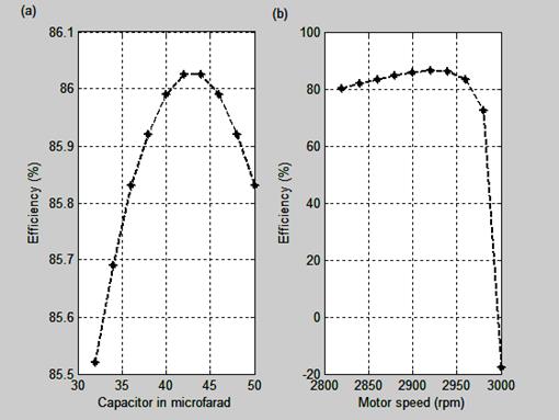
Figure 2. a) Efficiency-capacitor and b) Efficiency-Motor speed characteristics

Figure 3. Current versus Capacitor value and Motor speed characteristics
The motor draws current from the supply depending on the value of the capacitor connected to the auxiliary winding. As the capacitor value increases, the motor draws less current. The main winding current decreases with any increase in capacitor value or in the motor speed.
Figure 4 shows the capacitor voltage-capacitor value and Electromagnetic torque-capacitor value characteristics.
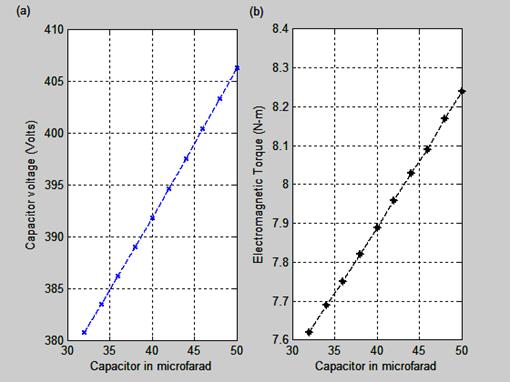
Figure 4. Capacitor voltage and Electromagnetic torque versus Capacitor value characteristics
The value of the capacitor connected to the auxiliary winding of permanent split capacitor induction motor is directly proportional to the capacitor voltage and the higher the value of the capacitor, the higher the value of the capacitor voltage and this is shown in Figure 4(a). Figure 4(b) shows that any increase in capacitor value results in the corresponding increase in the electromagnetic torque developed by the motor.
The power versus capacitor and the power versus motor speed characteristics are shown in Figure 5.
In Figure 5(a), as the value of the capacitor increases, the input power, the auxiliary winding power and the power shaft increase while the main winding power decreases. As the motor speed increases in Figure 5(b), the power shaft, the main winding power and the input power decrease while the auxiliary winding power gradually increases.
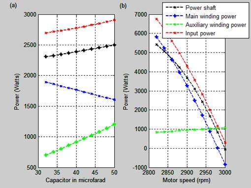
Figure 5. Power-capacitor and Power-motor speed characteristics
The difference between the input and shaft power is the power loss and this decreases as the motor speed increases thereby resulting in high efficiency of the motor.
The output parameters of PSC motor is shown in Table 3 as the motor speed varies:
Table 3. Output parameters for motor speed ranges from 2820 to 3000 rpm
|
Nr (rpm) |
Imain A |
Iaux A |
Is A |
Vc Volts |
Telm N-m |
Pshaft Watts |
Pmain Watts |
Paux Watts |
Pin Watts |
Eff (%) |
|
2820 |
31.34 |
4.39 |
33.61 |
324.12 |
18.48 |
5416.3 |
5814.8 |
837.68 |
6752.4 |
80.21 |
|
2840 |
28.37 |
4.53 |
30.72 |
335.21 |
17.21 |
5079.5 |
5242.8 |
865.26 |
6208.1 |
81.82 |
|
2860 |
25.29 |
4.68 |
27.68 |
346.72 |
15.77 |
4683.2 |
4626.2 |
892.82 |
5619.0 |
83.35 |
|
2880 |
22.12 |
4.84 |
24.51 |
358.61 |
14.13 |
4223 |
3964.5 |
920.11 |
4984.6 |
84.72 |
|
2900 |
18.92 |
5 |
21.23 |
370.84 |
12.30 |
3694.7 |
3257.9 |
946.83 |
4304.7 |
85.83 |
|
2920 |
15.78 |
5.18 |
17.83 |
383.34 |
10.25 |
3094.8 |
2507.9 |
972.64 |
3580.5 |
86.44 |
|
2940 |
12.90 |
5.35 |
14.40 |
396.04 |
7.99 |
2420.7 |
1716.7 |
997.15 |
2813.8 |
86.03 |
|
2960 |
10.68 |
5.52 |
11.08 |
408.86 |
5.52 |
1671.1 |
888.09 |
1020 |
2008.1 |
83.23 |
|
2980 |
9.80 |
5.7 |
8.21 |
421.71 |
2.84 |
845.8 |
27.13 |
1040.6 |
1167.8 |
72.43 |
|
3000 |
10.76 |
5.87 |
6.72 |
434.49 |
-0.04 |
-53.32 |
-859.64 |
1058.7 |
299.09 |
-17.82 |
The capacitor voltage obtained across the auxiliary winding depends on the motor speed. The higher the rating of the motor or rotor speed, the higher the value of the capacitor voltage that will be put across the auxiliary winding and this characteristic is shown in Figure 6. This result is obtained from Table 3.
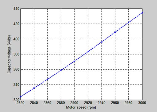
Figure 6. Capacitor voltage-motor speed characteristic
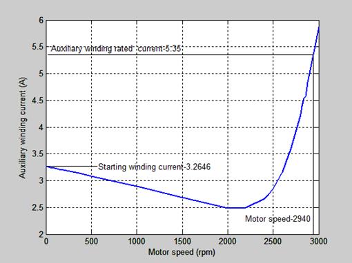
Figure 7. Auxiliary winding current versus Motor speed characteristic
The starting or auxiliary winding current versus motor speed characteristic is shown in Figure 7.
The starting current is low and is about 61.02% of the rated auxiliary winding current. This type of motor is required where low starting current is required.
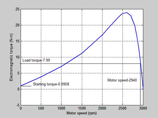
Figure 8. Mechanical torque-rotor speed characteristic
The Mechanical torque-motor speed characteristic of the
motor is shown in Figure 8. It is observed in Table 3 that at rated speed of
2940rpm, the rated torque is 7.99N-m and at starting torque in Figure 8, the starting
torque developed is 0.9958N-m. The motor has low starting torque of about ![]() of the rated
torque.
of the rated
torque.
Conclusion
The study of the permanent split capacitor induction motor shows that the motor is reliable due to the absence of centrifugal switch. With the aid of MATLAB programming and the results obtained, PSC induction motor capacitor value at optimum efficiency is determined. The motor has low starting torque, low starting current, higher efficiency, high pull out torque and high power factor. The characteristic of PSC induction motor is limited to where higher starting torque is required.
References
1. Angun A., Marizan B. S., Rosli O., Space vector analysis in electrical drives for single phase induction motor using MATLAB/SIMULINK, Journal of Theoretical and Applied Information Technology, 2013, p. 1-20.
2. Khalid G. M., New design correlations for single phase induction squirrel cage, Diyala Journal of Engineering Sciences, 2010, p. 133-139.
3. Enesi A. Y., Performance characteristics and double revolving theory of single phase induction motor, Leonardo Journal of Sciences, 2013, p. 1-12.
4. Krzysztof M., Marcin J. W., Determination of dynamic characteristics of the single phase capacitor induction motor, Wrocraw University of Technology, Institute of Electrical Machines, Drives and Measurements, 2011, p. 1-7.
5. Anthony C., Provide comfort/savings through a quality capacitor, 10 RSES Journal, 2013, p. 1-5.
6. Karmakar A., Roy N. R., Mukherjee R., Saha P. K., Panda G. K., Permanent capacitor single phase induction motor, D-Q Axis modelling and non-linear mathematical analysis and simulations, International Journal of Advanced Research in Electrical, Electronics and Instrumentation Engineering, 2012, p. 1-8.
7. Agarwal R. K., Principles of electrical machine design, Delhi, S.K. Kataria & Sons India, 2005.
8. Theraja B. L., A textbook of electrical technology, New Delhi-110 055 India, S.Chand & Company Ltd, 2008.
9. Smarajit G., Electrical machines, Second Edition, India, Pearson Education India, 2012.
10. Irving L. K., Electric machinery and transformer, Delhi, PHI Learning Private Limited India, 2008.
11. NRCan., Reference Guide Electric Motor (online). Available at: http://oee.nrcan.gc.ga/industrial/equipment/motors-ref/page-07.cfm (accessed 23/08/2011)
12. Razzaq A-Tahir A. A. (online), Study of single phase induction motor. Available at: http://eng.uokerbala.edu.iq/lectures/electrical_engineering/Second_year/Machines/Lecture Single Phase Induction Motor.pdf (accessed 19 /05/2012).