Active power filter improvement by new DC link for power quality enhancing
Hamidreza GOLSHANI*, Sayed Mohammad SHARIATMADAR
Islamic Azad University Nargh Branch, Tehran, Iran
E-mails: golshani.hr@gmail.com; shariatmadar@gmail.com
* Corresponding author, phone: +983136934322, +983136269993
Abstract
Active Power Filters (APFs) are one of the devices which could be applied for improving the Power Quality (PQ) indices such as harmonics, unbalances and voltage flicker. The most important topics in designing APFs are their correct control and especially suitable DC capacitor control for aforesaid parameters improvement. So in this paper, a new DC voltage link is developed by combining the fuzzy and PI control approaches into the predictive control structure. The presented DC link consists of a Fuzzy-PI Controller (FPIC). So, these parameters are modified by minimizing the errors between the DC link output and reference voltage. Finally, the output signal is added to two reference current achieved by incorporating the p-q theory. This method can almost improve the all PQ parameters such as harmonic, flicker, unbalances, power factor, etc. To test the APF in the worst conditions, an actual power system with nonlinear loads is considered. The aims of this paper are a new DC link of active power filter, power quality improvement based on fuzzy logic controller.
Keywords
Active Power Filter; DC Voltage Capacitor; p-q theory
Introduction
The proliferation of electronic non-linear loads such as switch mode power converters, power electronics operated adjustable speed drives, fluorescent lamps, arc furnaces, welding equipment and other non-linear loads in domestic, commercial and industrial installations has produced a serious concern in the field of electric power engineering due to distortion waveform and voltage disturbance in the power networks. The distortion waveform consists of harmonic, inter-harmonic, voltage flicker, noise and notch. Also, voltage unbalances, transients and short and long time phenomena as sag and swell voltage are classified in the disturbance category. The compensation for these parameters becomes increasingly important both for utilities and industries to feed their sensitive equipment with a suitable power quality, thereby avoiding malfunction and loss of revenue. Active Power Filters (APFs) are presently the most versatile and effective equipments to confront the challenge of reducing disturbances and distortions in power system. They are applicable of compensating the mentioned phenomena such as harmonics, unbalances, voltage flicker, etc., provided that their control system is appropriately designed. Hitherto, different methods have been presented such as Instantaneous Power Theory (IPT) [1-3], Direct Application of the Instantaneous Power Theory (DAIPT) [4,5], Synchronous Reference Frame Controller (SRFC) [6-9], p-q Theory (pqT) [10-12] and combined methods [13, 14].
The instantaneous power theory is used to detect reactive and harmonic current components and to determine proper compensating current components to feed back to the system. It has been proved with effective operation and good performance under balanced voltage source conditions. This method has been well-developed [14] for the purpose of line current compensation. This development is also known as active filter in power electronics technology. However, when the voltage source is meaningfully unbalanced, great errors may be resulted from calculation formula by direct application of the instantaneous power theory [3]. Reviewing system performance using the instantaneous power theory, it is difficult to operate efficiently under unbalanced three-phase voltage sources [5] to achieve reactive and harmonic current compensation. The SRFC method is based on positive, negative sequence and dc bus voltage that at first, load current harmonics are extracted in the d-q reference frame by positive sequence synchronous reference frame then, fundamental negative sequence load current and a DC bus voltage controller to regulate APF DC bus voltage are taken out by negative sequence [10].
The combine method has a good performance to improve the power quality phenomena in the worst condition [3]. This method is composed of three main parts: computation of reference currents, regulation of dc capacitor voltage, and production of firing pulses. In the mentioned method, the active filter control system is established upon the combination of the synchronous detection method and p-q theory [11].
In the all control methods, a DC regulator is applied for adjusting to a specific condition that APF can suitability improves the power quality in the power system. Therefore, this part of APF control is significantly important. This paper is applied the combined control based on [3], and formulated the appropriated dc capacitor voltage dependent upon Fuzzy-PI Controller (FPIC) and a Fuzzy Predictor (FP).
After the fuzzy logic was introduced as a model of a human thinking in order to remove the gap between the precision of math and the imprecision of the real world, the feasibility of it for controlling dynamic systems was recognized and this method is quickly developed and its application in different control system is increase in later years. Also, some applications of fuzzy logic are in different controllers as PID controllers which call fuzzy PID (FPID) [15-21]. The analyses of some direct action FPID controller structures are investigated in [15]. To develop the FPID, A robust fuzzy-PID control scheme is suggest by unifying an optimal fuzzy reasoning into a well-developed PID type of control framework [16]. In the next, a FPID controller is developed by first describing the discrete-time linear PID control law and then gradually deriving the steps necessary to incorporate a fuzzy logic control mechanism into the modifications of the PID structure [17]. A function-based evaluation approach is recommended for a systematic study of FPID like controllers addressing simplicity and nonlinearity issues and A BIBO (bounded-input bounded-output) stability analysis of a FPID control was given. Then a fuzzy predictive controller based on the fuzzy optimization frame for multi objective satisfaction problems are suggested and the methods for effective optimization in fuzzy model predictive control have been compared in [18-21].
Briefly, in this paper, at first an APF is designed based on combined method [3]. Then, to improve the control system, the fuzzy PI is presented for stabilizing and increasing speed operation of that. In this method, the error terms to fuzzy instead of multiplying with the scalar PI gains. The FPIC parameters are adjusted by minimizing a projected cost function that penalizes the sum of the squared errors between the plant outputs and reference trajectories. In the application part, an identical FPI controller of the adaptation part is used to control the actual plant. The adjusted parameter values are transferred to this identical controller at each time step. Now, the APF must be tested at the worst conditions, hence, the power system with nonlinear load is considered. This load can generate the harmonics, unbalances, fluctuations and etc. in power system and the APF designed should improve those parameters. The APF operation is compared with APF in [3] to analyze proposed control.
Material and method
Active power filter design
The single line diagram (SLD) of a supplying source of nonlinear load with the APF is shown in Figure 1. In this figure, bus 1 indicates the point of common coupling (PCC), which is the supplying bus of nonlinear load such as rectifiers and compensated with APF. The devises are also connected to the PCC through the transformer TS, (HV/MV). In this figure, XLsc is the short circuit reactance at bus PCC.
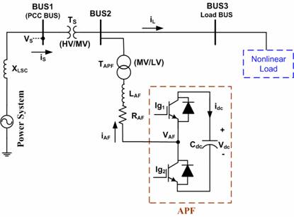
Figure 1. Power system with APF and EAF loads
In Figure 1, the APF transformer, TAPF (MV/LV), connects the compensator to power system. The purpose of applying this transformer is to reduce the voltage level on the APF for implementation. The used APF is composed of six insulated-gate bipolar transistors (IGBT) switches and one DC capacitor. Among many reasons in using IGBT, the high speed in switching and lack of necessity of commutation circuits are important.
The structure of the proposed control system for the APF is illustrated in Figure 2. This control is based on combination of p-q theory and new DC voltage link by FPIC method. According to this figure, the converted vectors of voltage and currents are used in a α-β system as follows in order to compute the instantaneous active and reactive powers in power system:
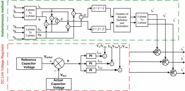
Figure 2. Proposed control system of APF
The instantaneous are calculated as follows [3]:
|
|
(1) |

Therefore,
|
|
(2) |

where:  . It should be noted
that the active power is transferred through components iαp, iβp
and components iα and iβ do not have any role
in this power transportation. Therefore, the reference currents for the
reactive power compensation (the main component and harmonic components) are
calculated as follows:
. It should be noted
that the active power is transferred through components iαp, iβp
and components iα and iβ do not have any role
in this power transportation. Therefore, the reference currents for the
reactive power compensation (the main component and harmonic components) are
calculated as follows:
|
|
(3) |

When the currents and voltages are sinusoidal and balanced, both the p and q powers will be of constant values. However, with harmonics or imbalanced currents, the p and q powers are no longer constants, and they can be expressed as follows [3]:
|
|
(4) |

where,
·
![]() ,
,
![]() : Active
and reactive powers relevant to non harmonic and balanced currents;
: Active
and reactive powers relevant to non harmonic and balanced currents;
·
![]() ,
,
![]() : Active
and reactive powers relevant to the harmonic and current negative components;
: Active
and reactive powers relevant to the harmonic and current negative components;
·
![]() ,
,
![]() : Active
and reactive powers relevant to the negative component of a three-phase
currents;
: Active
and reactive powers relevant to the negative component of a three-phase
currents;
·
![]() ,
,
![]() : Active
and reactive powers relevant to the harmonic components of a three-phase
currents.
: Active
and reactive powers relevant to the harmonic components of a three-phase
currents.
In order to improve the power quality indices in power systems, different parameters can be defined to create reference currents, as shown in Table 1.
Table 1. The list of parameters applied in the APF control
|
Definitions |
The used variables in the control system |
|
|
The goal of compensating |
ipc |
iqc |
|
Compensating for harmonics and balancing the current |
|
|
|
Compensating for the main component of the reactive power |
0 |
|
|
Compensating for the unbalanced current and the main component of the reactive power |
|
|
|
Compensating for harmonics, unbalanced current and the reactive power |
|
iq |
|
Compensating for harmonics and flicker of the voltage |
|
|
Based on the available definitions in this table, the majority of the power quality indices in power systems can be set in allowable ranges.
The second part includes the DC capacitor voltage regulator of APF. After calculation of incipient currents, the DC capacitor voltage must be kept at a constant level for the proper operation of the APF. Considering Eq.(5), if the capacitor voltage is constant, the actual power value exchanged between the capacitor and the power system in stable conditions will be zero.
|
|
(5) |
|
|
(6) |
|
|
(7) |
where, νdca is
average DC voltage, Tx, sampling time, ![]() , required energy to achieve the
reference voltage, Icp, current peak that is in phase with the
voltage.
, required energy to achieve the
reference voltage, Icp, current peak that is in phase with the
voltage.
However, under transient conditions, the capacitor voltage changes, and the active power is thus exchanged with the system. Therefore, this power should be included in the control system in such a way that the capacitor voltage remains stable. In Figure 2, the capacitor voltage produces the error signal (e) after being compared with the reference voltage. This signal and its derivation produce the signal (Icp) after passing through a proportional-integral controller (PIC) in series with a limiter. This controller has simple structures and robust performances and the discrete-time PI controller is defined in the incremental form as below:
|
|
(8) |
where KP, KI are the proportional and integral gains, respectively, T is the sampling period, u is the output of the PI controller, and k is the discrete time index. The error term (e =r-y) is defined as the difference between the reference input (r) and the actual voltage of DC link (y). Now, by defining the following error terms Eq.(11) can be simplified the PIC equation:
|
|
(9) |
|
|
(10) |
The incremental control signal is achieved by multiplying these error terms with PI gains. Regarding to Eq.(9), (10) can be rewritten as below Eq.(11):
|
|
(11) |
The PIC output shows the exchanged active current peak between the APF and the system. This current is in phase with the corresponding voltage. It can be multiplied by the per-unit voltage and will be changed into a sinusoidal current with an Icp peak that is in phase with the voltage. This signal is then added to the reference signal to produce the final reference signal. Hence; most important topic in this part is calculation of PIC parameters. In regarding to different parameters changes in power system with nonlinear loads, general PIC could not improve the APF. To achieve the optimal PIC parameters, the fuzzy controller based on fuzzy logic method is proposed.
In a fuzzy logic controller (Figure 3), the control action is determined from the evaluation of a set of simple linguistic rules. The development of the rules requires a thorough understanding of the process to be controlled, but it does not require a mathematical model of the system.
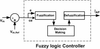
Figure 3. Final FPIC
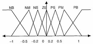
The internal structure of the fuzzy controller is shown in Figure 4 (a-b). Here, the error e and change of error ce are used as numerical variables from the real system. To convert these numerical variables into linguistic variables, the following seven fuzzy levels or sets are chosen as [15]: negative big (NB), negative medium (NM), negative small (NS), zero (ZE), positive small (PS), positive medium (PM) and positive big (PB). It is designed that seven fizzy sets for each input and output, triangular membership functions for simplicity is selected. The final fuzzy logic controller is shown in Figure 3. Therefore, Figure 4 shows the normalized triangular membership functions used in fuzzification.
|
 a)
a)
|
 b)
b)
Figure 4. a)Error 'e' and change in error 'ce'; b)Change in reference current
The different rules are selected based on Table 2. This table is applied to fuzzy logic controller base on step response of PI controller.
Table 2. Control rule table
|
e |
|
|||||||
|
PB |
PM |
PS |
ZE |
NS |
NM |
NB |
||
|
ZE |
NS |
NM |
NB |
NB |
NB |
NB |
NB |
ce |
|
PS |
ZE |
NS |
NM |
NB |
NB |
NB |
NM |
|
|
PM |
PS |
ZE |
NS |
NM |
NB |
NB |
NS |
|
|
PB |
PM |
PS |
ZE |
NS |
NM |
NB |
ZE |
|
|
PB |
PB |
PM |
PS |
ZE |
NS |
NM |
PS |
|
|
PB |
PB |
PB |
PM |
PS |
ZE |
NS |
PM |
|
|
PB |
PB |
PB |
PB |
PM |
PS |
ZE |
PB |
|
This table is based on the theory that in the transient state, large errors need coarse control, which requires coarse input/output variables; in the steady state, however, small errors need fine control, which requires fine input/output variables. Based on this, the elements of the rule table are obtained from an understanding of the filter behavior and modified by simulation performance.
Results
The selected parameters for the circuit diagram presented in Figure 1 are summarized in Table 3.
Table 3. The power system parameters
|
Different parameters |
|
|
Supplying system |
SSC = 11MVA, V = 20kV, Xth = 14.5µΩ, f = 50Hz |
|
Load |
The load is a rectifier that can change the its characteristic: RL = 5.6 and 9.7 Ω, LL = 20 mH. |
Now, the results of the APF design for the nonlinear load are presented and compared with the state of being without APF. So, it is assumed that the load is connected to power system and APF is connected at t = 0.25 sec. The different parameters of the designed APF are shown in Table. 4. Also this table shows the values of ordinary PIC are calculated by trial and error method. As the value of hysteresis band is selected to be equal to 0.0001, the switching frequency is therefore equal to 10 kHz. This frequency correctly shows the APF capabilities.
Table 4. The design APF parameters
|
Active Power Filter |
c = 1000µF |
|
Hysterias Band |
T = 0.0001 |
|
PI Controller (Second part) |
Kp = 0.633 Ki = 0.0073 |
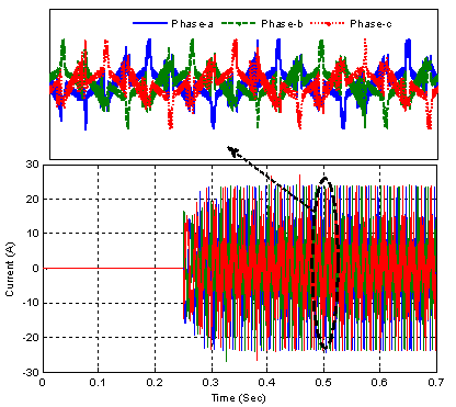
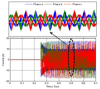
By Considering Figure 1 and Figure 2, the actual current and the computed reference current waveforms at different conditions: with PIC and FPIC are shown in Figure 5(a) and 5(b). In this figure, the actual current follows the reference current in a suitable manner by means FPIC. The resulting error of these two currents is about 1.5% at FPIC and 13% at PIC. It should be noted, the PI parameters are effective in following reference current. Therefore the proposed method can generate the best reference current and the actual current follows it with minimum error. This issue shows the desired design of the APF control system by means proposed method. Figure 6(a) and 6(b) show the power system current before and after connecting the APF with PIC and FPIC respectively.
 a)
a)
 b)
b)
Figure 5. Actual current of APF in a) PIC and in b) Proposed method
 a)
a)
 b)
b)
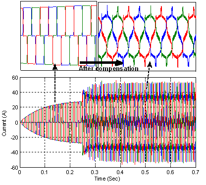
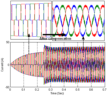
Figure 6. Power system current after and before compensation a) PIC b)FPIC
As can be seen in this figure, the APF can convert the power system current to sinusoidal current. By a comparing between the Figure 6 (a) and (b) it can be concluded that the new DC link based on fuzzy logic method has better operation than pervious method.
Figure 7 shows the waveform of the DC capacitor voltage of the APF with its reference. The DC capacitor voltage follows the reference voltage and improves the APF operation. In this figure, the reference voltage error arising from the proposed method is about 0.6% in FPIC and 19% in PIC, which justifies the suitability of the proposed control system. Hence, it can be argued that the capacitor voltage is stabilized very well; as a result, the steady state value of the exchanged active power between the capacitor and the power system in permanent mode will be zero. Thus, the operation of the APF control system is more desirable.
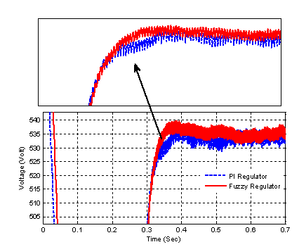
Figure 7. Capacitor voltage at DC link with FPIC and PIC
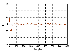
According to recent figures, eP(k) and eI(k) changes are shown in Figure 8.
Figure 9 shows the curves of the voltage profile with and without APF in the main bus of the system (BUS1), with PIC and FPIC respectively. It can be observed that the proposed method improves the voltage fluctuations very well.
 a)
a)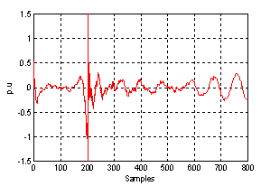 b)
b)
Figure 8. FPIC errors in proposed control: a) eP(k) and b) eI(k)
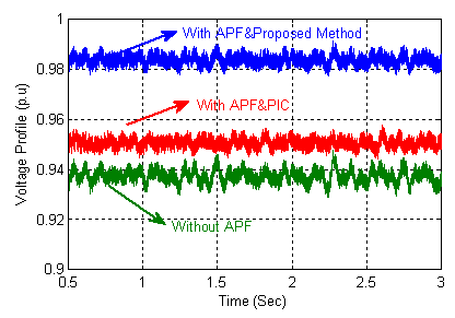
Figure 9. Voltage fluctuation changes at BUS1 with FPIC and PIC APF and without APF
The current harmonic spectra in the BUS1 of the power system (Figure 1) with APF, PIC and proposed method, and without the APF and IEC standard are depicted in Figure 10. The harmonic spectrum presented, based on the percentage of the fundamental component, is expressed for each harmonic order. In this figure, the harmonics of the main bus current are substantially reduced. For example, the 5th harmonic without the APF was about 35% of the fundamental component and the one with the PIC-APF it is reduced to 13.6% and with FPIC-APF is 4.95%. The THD is equal to 30.1% without the APF and is reduced to 13.1% with the PIC-APF and 5.3% with proposed method.
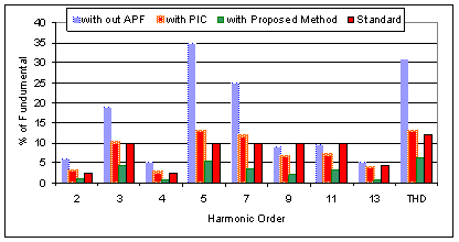
Figure 10. Current harmonics orders and THD
The advantages of the FPIC-APF design are:
1. In proposed method-APF, the actual current of the APF follows the reference current at all times, which is true even if the flicker of the voltage fluctuates randomly. The error produced here is about 1.5% at proposed method however this error is 13% in PIC-APF because of sensitiveness PI parameters in design routine and their effectiveness in generating reference current and consequently reduced accuracy in following it by means of actual current.
2. By obtaining a constant DC capacitor voltage, the real power exchange between the capacitor and the power system is zero in all conditions. So, the new proposed DC link in all time is stable and this situation leads to the desired operation of the FPIC-APF.
3. The current and voltage harmonics in the main bus of the power system are compensated with PIC-APF and the THD value in this bus is significantly reduced and is in the IEC-standard range.
4. The reactive power in the main bus of the system reaches almost zero by PIC-APF, and the power factor is naturally increased in this bus. Also the FPIC-APF is very fast than PIC-APF. The voltage flicker is reduced and is standard. Also and the voltage profile is improved at the 1-p.u level in the main bus of the system.
5. Another important advantage of this method is the possibility of its actual implementation for the investigation of power system operations.
Conclusion
The simulation results show that the designed APF is able to improve the power quality phenomenon and to compensate the harmonics in the power system. This method can implemented for electric distributed network. Also, this method can be used for nonlinear loads with intense changes of characteristics.
References
1. Akagi H., Kanazawa Y., Nabae A., Instantaneous reactive power compensators comprising switching devices without energy storage components, IEEE Trans. on Industrial Application, 1984, 20(3), p. 625-630.
2. Kim H., Blaabjerg F., Bak-Jensen B., Choi J., Instantaneous power compensation in three-phase systems by using p-q-r theory, IEEE Trans. on Power Electronic, 2002, 17(5), p. 701-710.
3. Hooshmand R., Torabian Esfahani M., A new combined method in active filter design for power quality improvement in power systems, Elsevier Journal, ISA Transactions, 2011, 50(2), p. 150-158.
4. Montero M. I. M., Cadaval E. R., Gonzalez F. B., Comparison of control strategies for shunt active power filters in three phase four wire systems, IEEE Trans. on Power Electronic, 2007, 22(1), p. 229-236.
5. Herrera R. S., Salmeron P., Kim H., Instantaneous reactive power theory applied to active power filter compensation: different approaches, assessment and experimental results, IEEE Trans. on Industrial Electronic, 2008, 55(1), p. 184-196.
6. Mattavelli P., Synchronous frame harmonic control for high-performance AC power supplies, IEEE Trans. on Industrial Application, 2001, 37(3), p. 864-872.
7. Escobar G., Stancovic A. M., Mattavelli P., An adaptive controller in stationary reference frame for D-STATCOM in unbalance operation, IEEE Trans. on Industrial Electronic, 2004, 51(2), p. 401-409.
8. Chaoui A., Gaubert J., Krim F., On the design of shunt active filter for improving power quality, IEEE International Symposium on Industrial Electronics (ISIE), 2008, p. 31-37.
9. Hu W., Kang Y., The shunt active power filter based on ip-iq detecting method and hysteresis control, International Conference on Electrical Machines and Systems (ICEMS), 2008, p. 2071-2076.
10. Wang X., Liu J., Hu J., Meng Y., Ch. Yuan, Frequency characteristics of the d-q synchronous-frame current reference generation methods for Active Power Filter, International Conference on Power Electronics, 2008, p. 945-950.
11. Chen C. L., Lin C. E., Huang C. L., The reference active source current for Active Power Filter in an unbalanced three-phase power system via the synchronous Detection method, Instrumentation and Measurement Technology Conference (IMTC), 1994, p. 502-505.
12. Girgis A. A., Chang W. B., Makram E. B., A digital recursive measurement scheme for online tracking of power system harmonics, IEEE Trans. on Power Delivery, 1991, 6(3), p. 1153-1160.
13. Qiu Z., Zhao W., Chen G., Study on shunt active power filter with high quality grid current waveform, IEEE Conference on Applied Power Electronics Conference and Exposition (APEC), 2008, p. 933-938.
14. Henrique C., Pereira1 R., Eduardo L., Dead-time compensation in shunt active power filters using fast feedback loop, International Conference on Harmonics and Quality of Power (ICHQP), 2008, p. 1-4.
15. Mann G. K. I., Hu B. G., Gosine R. G., Analysis of direct action fuzzy PID controllers structures, IEEE Transactions on Systems, Man and Cybernetics – Part B: Cybernetics 1999, 29(3), p. 371-388.
16. Li H. X., Zhang L., Cai K. Y., Chen G., An improved robust fuzzy-PID controller with optimal fuzzy reasoning, IEEE Transactions on Systems, Man and Cybernetics – Part B: Cybernetics, 2005, 35(6), p. 1283-1294.
17. Carvajal J., Chen G., Ogmen H., Fuzzy PID controller: design, performance evaluation, and stability analysis, Information Sciences, 2000, 123(3-4), p. 249-270.
18. Hu B. G., Mann G. K. I., Gosine R. G., A systematic study of fuzzy PID controllers function- based evaluation approach, IEEE Transactions on Fuzzy Systems, 2001, 9(5) p. 699-712.
19. Mohan B. M., Sinha A., Analytical structure and stability analysis of a fuzzy PID controller, Applied Soft Computing, 2008, 8(1), p. 749-758.
20. Flores A., Sáez D., Araya J., Cipriano M., Fuzzy predictive control of a solar power plant, IEEE Transactions on Fuzzy Systems, 2005, 13(1) p. 58-68.
21. Mollov S., Babuska R., Abonyi J., Verbruggen H. B., Effective optimization for fuzzy model predictive control, IEEE Transactions on Fuzzy Systems, 2004, 12(5) p. 661-675.