Novel Koch fractal circularly polarized micro strip antenna for global positioning system application
Kavalipati Phani SRINIVAS1, Boddapati Taraka Phani MADHAV1,*, Dintakurthi Sai Krishna TEJA2, Maddela Venkata Krishna SUPREETH2, Nadendla Surya TEJA2, and A. CHARITHA2
1Associate Professor, Department of ECE, K L University, AP, India
2Engineering Project Students, Department of ECE, K L University, AP, India
E-mails: phanisrinivas@kluniversity.in; *btpmadhav@kluniversity.in; krish24129@gmail.com; nadendlasurya@gmail.com, supreethkrishna7@gmail.com; supreethkrishna7@gmail.com
* Corresponding author, phone: +91-9908243452
Abstract
A Novel compact Koch fractal microstrip antenna is designed for Global Positioning System (GPS) Application in this paper. The Proposed Model Consisting of Koch fractal iterations on a square patch surface which exhibiting circular polarization. The proposed structure of the antenna seems to be like triangular asymmetric slots on the edges of the radiating element with co-axial feeding for excitation. The current model is resonating at single band with return loss less than -10dB and 3dB axial ratio bandwidth makes the antenna applicable to Global Positioning System with considerable bandwidth. The proposed fractal antenna model is fabricated on FR4 substrate with dielectric constant 4.4 and thickness 1.6mm. The analytical study of the current design is simulated using HFSS tool and the experimental validation is performed on ZNB20 vector network analyzer (VNA).
Keywords
Axial ratio; Bandwidth; Circular polarization (CP); Flame retardant 4 (FR4); Global positioning system (GPS); Koch Fractal
Introduction
The explosive growth of the navigational system in the communication engineering opens new challenges in the design as well as in the applications. The Wireless communication technology is growing in all the fields to extend its application with several advantages to the users [1-2]. There are many wireless applications that satisfy different needs for the people working in agriculture, defence, industry, medicine and lot more especially when we speak about the navigational application to the defence and transport related fields [3-6]. The advancement in the communication is very much needed for several purposes. Generally, wireless devices are expected to operate over different frequency bands in the range from 400MHz up to 6GHz with bandwidths from 1.4 to 20 MHz.
On the other hand, it is useful to notice that the design of antenna based on fractal proved to be an effective solution when dealing with the single, dual, triple and multiband radiating systems. Generally, Fractal shapes are used to design multiband antennas, but some of them have potential wide band properties at single band also. The property of self similarity of fractal geometry is used to achieve multiband operations from fractal antennas and this space filling property is used for antenna miniaturization [7-10]. Fractal geometrics are used in radiating systems and even in microwave devices for different design. Since, the generation of the fractal configuration has an iterative procedure; they can achieve long linear dimensions and high surface area in a limited volume [11-14].
In this paper, a single band circularly polarized compact fractal antenna is designed to operate at Global Positioning System frequency band. The Global Positioning System (GPS 1.575GHZ) is the worldwide acceptable frequency band for the desired operation in many communication systems. The proposed antenna is very much suitable for the navigational systems and which can be placed in the tracking devices in different fields. The proposed model is compact in size and circular polarization makes it suitable for high efficient radiating system. The complete analysis regarding the design and operational characteristics are carried out using HFSS Tool and presented the antenna performance in subsequent sections.
Material and method
Antenna design and geometry
Initially, considering primary characteristics of an antenna, the modelling is done in a systematic way. Basically stated with the design of square patch antenna with operating band nearer to GPS operating band, different Iteration are carried to get the proposed antenna model with circular polarization as shown in Figure 1. Figure 2 shows the dimensional characteristics of the proposed model and table 1 shows the supporting values.
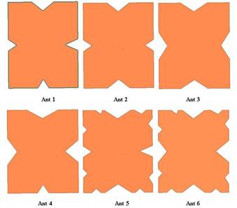
Figure 1. Antenna Iterations
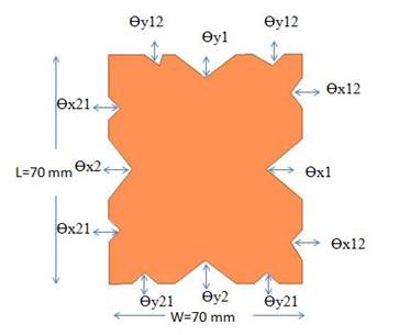
Figure 2. Proposed Antenna Model
Table 1. Antenna dimensions
|
L (mm) |
W (mm) |
Өx1 (mm) |
Өx2 (mm) |
Өy1 (mm) |
Өy2 (mm) |
Өx12 (mm) |
Өx21 (mm) |
Өy12 (mm) |
Өy21 (mm) |
|
70 |
70 |
11.745 |
7.745 |
7.745 |
7.645 |
3.745 |
3.745 |
3.645 |
3.645 |
Once a square patch is designed to operate at a particular frequency near to the GPS band, the miniaturization is done by placing slots at the edges of the patch element are presented in Figure 1. The four sides of the square patch are replaced by fractal curve of different iteration for circular polarization. Structural realization with the use of asymmetrical Koch fractal curves as edges of a single feed square patch gives the possible to excite two orthogonal modes with 90° phase shift for circular polarization radiation. The detailed analysis related to the antenna parameters are presented in results and analysis sections.
The current antenna model design, simulation and operational verification is carried out in this way
1) Mathematical formulation for the antenna iterations are calculated from standard Koch fractal literature data.
2) Finite element method based electromagnetic tool is used to design the antenna iterations.
3) Basic simulation for functional verification at fixed operating frequency is done with HFSS software.
4) Parametric analysis for optimization is performed before the fabrication
5) Optimized antenna model is prototyped on FR4 substrate material
6) Measurement results are collected from ZNB 20 vector network analyzer and compared with simulated results for validation.
Results and discussion
The original antenna is chosen to be a square in order to excite two modes with close resonant frequencies required for circular polarization. Asymmetry in the structure is introduced through edges; so that co-axial line feed point is along the diagonal of the patch. Both LHCP and RHCP can be obtained by shifting the feed point to accurate positions on the diagonal axis.
Figure 3 shows the antenna reflection coefficient crack for different iteration from 1 to 6 reflection coefficient curve.
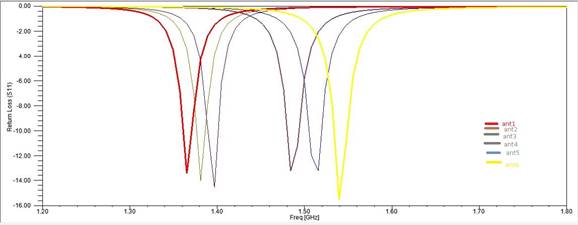
Figure 3. Return loss Vs Frequency
The iteration 1 shows a resonant frequency at 1.36GHZ with impedance bandwidth of 7 %. Iteration 2 model is resonant frequency at 1.38GHZ with impedance bandwidth of 6% when moving from iteration 1 to 6, it is observed a consideration shift in the resonating frequency from lower frequency to high frequency band. The proposed Koch fractal circular polarized antenna is resonating at 1.56GHZ with impedance bandwidth of 12%.
Figure 4 shows the antenna 3 dimensional radiation pattern with gain more than 7.46dB. Figure 5 also gives the radiation characteristics of the proposed antenna in polar co-ordinates.
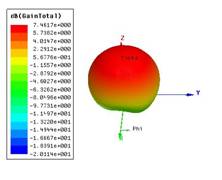
Figure 4. Radiation in 3D Figure 5. Radiation in Polar Coordinates
It has been observed that the antenna is circular polarized with maximum gain towards Z direction. Figure 6 shows the current distribution over the surface of the antenna at resonant frequency.
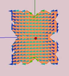
Figure 6. Surface current distribution
The intensity of the current elements is strong in the middle surface of the radiating element rashes the edges. This strongest current distribution along the y axis is giving rise to fundamental excited mode TM10.Along the x axis, TM01 Mode is propagating. The circular polarization curve is observed from the movement of current distribution elements at the minimum axial ratio frequency in circular passion.
Figure 7 shows the directivity of the antenna at the resonant frequency about 6dB and gains more than 7.46dB.
Figure 7. Frequency Vs gain and directivity
Table 2 shows the complete operation parametric analysis of all the antenna iteration models.
Table 2. Antenna parameters
Configuration |
Operating freq (GHz) |
Return loss (dB) |
Gain (dB) |
Effective area (mm2) |
Axial ratio (dB) |
|
Ant 1 |
1.3653 |
13.421 |
5.82 |
4568.03 |
0.340 |
|
Ant 2 |
1.4840 |
13.198 |
7.24 |
4549.81 |
0.807 |
|
Ant 3 |
1.5156 |
13.175 |
7.35 |
4410.80 |
1.088 |
|
Ant 4 |
1.3969 |
14.538 |
6.05 |
4412.51 |
0.362 |
|
Ant 5 |
1.3811 |
13.991 |
5.77 |
4371.41 |
0.294 |
|
Ant 6 |
1.5394 |
15.352 |
7.45 |
4304.54 |
1.800 |
As per the size is concerned, the proposed model is occupying compact space compared to over iteration models. The gain and directivity is also more for the proposed circularly polarized antenna. The axial ratio is the also less than 3dB for the proposed antenna model. The efficiency of the antenna is also more than 90%. Figure 8 shows the radiation efficiency of the proposed antenna at the resonant frequency.

Figure 8. Fabricated Prototype of Proposed Antenna
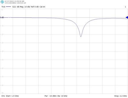
Figure 9. Measured S11 parameter on ZNB 20 VNA
Prototyped antenna is fabricated on FR4 substrate with thickness 1.6 mm. Figure 8 shows the fabricated antenna photograph taken at LCRC-R&D. Figure 9 shows the measured S11 parameter with ZNB 20 vector network analyzer. The simulation and measurement results are in good agreement with other corresponding to its resonant frequencies.
Conclusions
A circularly polarised Koch fractal antenna is designed to operate at GPS band application. The proposed antenna is showing circular polarization and axial ratio less than 3 dB with good radiational characteristics and considerable bandwidth at resonating frequency. The gain of the antenna is more than 7.4 dB at corresponding resonant frequency and the overall size of the antenna is around 70×70×1.6 mm.
The prototyped antenna on FR4 substrate is also providing similar kind of results in comparision with the simulation results, which gives the motivation to apply the proposed antenna in desired band of applications for global positioning communication systems. This type of antenna is best suited for navigational reelated fields with global positional applications.
Acknowledgements
Authors would like to express their gratitude towards the department of ECE and management of K L University for their support and encouragement during this work. Further Madhav likes to express his gratitude to DST through FIST grant SR/FST/ETI-316/2012.
References
1. Madhav B. T. P., Pisipati V. G. K. M., Bhavani K. V. L., Sreekanth P., Kumar P. R., Rectangular Microstrip Patch Antenna on Liquid Crystal Polymer Substrate, Journal of Theoretical and Applied Information Technology, 2010, 18(1), 62-66.
2. Madhav B. T. P., Chhatkuli S., Manikantaprasanth A., Bhargav Y., Sai U. D. N. V., Feeraz S., Measurement of Dimensional Characteristics of Microstrip Antenna based on Mathematical Formulation, International Journal of Applied Engineering Research, 2014, 9(9), p. 1063-1074.
3. Reddy V. V., Sarma N. V. S. N., Compact circularly polarized asymmetrical fractal boundary micro strip antenna for wireless applications, IEEE Antennas and Wireless Propagation Letters, 2014, 13, p. 118-121.
4. Chen W.-L., Wang G.-M., Zhang C.-X., Small-size microstrip patch antennas combining Koch and Sierpinski fractal-shapes, Antennas and Wireless Propagation Letters IEEE, 2008, 7, p. 738-741.
5. Rakesh D., Kumar P. R., Madhav B. T. P., Khan H., Kavya K. C. S., Kumar K. P., Bala S., Prasad D., Performance Evaluation of Microstrip Square Patch Antenna on Different Substrate Materials, Journal of Theoretical and Applied Information Technology, 2011, 26(2), 97-106.
6. Sharma P. C., Gupta K. C., Analysis and optimized design of single feed circularly polarized microstrip antennas, IEEE Trans. Antennas Propag, 1983, 31(6), p. 949-955.
7. Madhav B. T. P., Vaishnavi G., Manichandana V., Reddy Ch. H., Teja S. R., Kumar J. S., Compact Sierpinski Carpet Antenna on Destructive Ground Plane, International Journal of Applied Engineering Research, 2013, 8(4), p. 343-352.
8. Madhav B. T. P., Ujwala D., Chowdary J. R., Reddy A. S. N., Kranthi Ch., Kumar Bidichandani S., Design and Analysis of New Sierpinski Carpet Fractal antenna, International Journal of Microwaves Applications, 2013, 2(3), p. 108-112.
9. Madhav B. T. P., Yedla K. N., Kumar G. S., Rahul R., Fractal aperture EBG ground structured dual band planar slot antenna, International Journal of Applied Engineering Research, 2014, 9(5), p. 515-524.
10. Madhav B. T. P., Pisipati V. G. K. M., Khan H., Ujwala D., Fractal shaped Sierpinski on EBG structured ground plane, Leonardo Electronic Journal of Practices and Technologies, 2014(25), p. 26-35.
11. Iwasaki H., A circularly polarized small size microstrip antenna with cross slot, IEEE Trans. Antennas Propag, 1996, 44(10), p. 1399-1402.
12. WenShyang C., Chum-Kum K.-L., Wong K.-L., Novel compact circularly polarized square microstrip antenna, IEEE Trans. AntennasPropag., 2001, 49(3), p. 340-342.
13. Bahl I. J., Bhartia P., Microstrip Antennas, Artech House, 1981.
14. Sung Y., Dual-band circularly polarized pentagonal slot antenna, IEEE Antennas Wireless Propag Lett., 2011, 10, p. 259-261.