Possibilities of implementation of synchronous Ethernet in popular Ethernet version using timing and interference constraints
Seetaiah KILARU1,*, Bhargava PULI2, and Shwetha PULI3
1Department of Electronics &
Communication Engineering, Institute of Aeronautical Engineering,
2Wipro Technologies,
3II/II
M. Tech Scholor, Annamacharya
E-mails: dr.seetaiah@gmail.com; csebhargava@gmail.com; eceshwetha@gmail.com
* Corresponding author, phone: +919505740860
Abstract
Popular network architectures are following packet based architectures instead of conventional Time division multiplexing. The existed Ethernet is basically asynchronous in nature and was not designed based on timing transfer constraints. To achieve the challenge of next generation network with respect to efficient bandwidth and faster data rates, we have to deploy the network which has less latency. This can be achieved by Synchronous Ethernet (Sync-E). In Sync-E, Phase Locked Loop (PLL) was used to recover the incoming jitter from clock recovery circuit. Then feed the PLL block to transmission device. We have to design the network in an unaffected way that the functions of Ethernet should run in normal way even we introduced timing path at physical layer. This paper will give detailed outlook on how Sync-E is achieved from Asynchronous format. Reference model of 100 Base-TX/FX was analyzed with respect to timing and interference constraints. Finally, it was analyzed with the data rate improvement with the proposed method.
Keywords
Synchronous Ethernet; Timing and interface; Phase locked loop; Physical layer; Frequency synchronization; Phase synchronization; Clock; Accuracy
Introduction
All networks and services are moving towards IP technology. Hence, conventional technique Synchronous Digital Hierarchy (SDH) also needs to move towards IP based architecture. In this process, implementation of Time Division Multiplexing (TDM) in new scenario is a challenging task. In general, TDM is used for Voice communication and it follows clock synchronization [1]. IP networks will not follow synchronization. Voice over IP (VOIP) serves for voice users in IP but clock synchronization is not matured to desired level. The regularization of several computer/nodes internal clocks are required to get effective output. Even the clocks were initially synchronized; they may differ after particular period due to clock drift [2].
Frequency synchronization
All the devices which are connected to the single network should work on single rate; it is possible only with the frequency synchronization. Pulse Code Modulation (PCM) is used to represent sampled analogue signal in digital signal. PCM will convert information into discrete pulses and these pulses were transmitted through network. The perfect transmission of information among different systems connected in that computer network depends on synchronization of clock frequencies. A synchronization of these clock pulses lead to information loss on defined network [3].
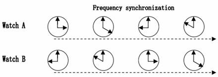
Figure 1. Frequency synchronization
From Figure 1, it is observed that watch A and watch B may show different time but the timing difference between them was constant. The timing difference for the above figure was 6 hours.
Time synchronization
Internal clocks of the communication network will vary from system to system. Based on the information of received time the system will adjust its internal clock. Time synchronization adjusts the clock based on received time information. Phase Locked Loop (PLL) is used to adjust the output phase of the output signal with the phase of input signal. PLL adjustment should always be periodical. Time synchronization is also called as phase synchronization [4].
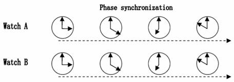
Figure 2. Time/Phase synchronization
In Figure 2, watch A and B are showing synchronization with time. Both watches always kept at the same time in Time synchronization.
Clock synchronization implementation varies with communication access method. The following Table 1 shows the requirements of clock synchronization for different wireless access standards.
Table 1. Requirement of wireless access methods with respect to synchronization
|
No |
Wireless access method |
Phase synchronization accuracy |
Frequency synchronization accuracy as Parts Per Million (PPM) |
|
1 |
LTE |
Preferred |
0.05 |
|
2 |
Wi-Max TDD |
1 μs |
0.05 |
|
3 |
Wi-Max FDD |
Not applicable |
0.05 |
|
4 |
CDMA-2000 |
3 μs |
0.05 |
|
5 |
TD-SCDMA |
3 μs |
0.05 |
|
6 |
WCDMA |
Not applicable |
0.05 |
|
7 |
GSM |
Not applicable |
0.05 |
GSM and WCDMA are using asynchronous technology; hence there is no need to maintain Time/Phase synchronization. They are following frequency synchronization only.
Ethernet is a technique which follow store and forward architecture, means that before forwarding, it can store the whole datagram. Finally, there are many possibilities are there to observe non-deterministic latency behavior. The following Table 2 represents latency measurement of 100 Mbps over one meter line [5].
Table 2. Latency measurement of 100 mbps over 1 meter line
|
Size of the packet in bytes |
Expected latency (micro seconds) |
Only forwarding delay (micro seconds) |
|
64 |
7.7 |
2.6 |
|
128 |
12.9 |
2.6 |
|
256 |
23.6 |
2.7 |
|
512 |
42.8 |
2.7 |
|
1024 |
80.5 |
2.8 |
|
1280 |
106.7 |
2.8 |
|
1518 |
122.0 |
2.9 |
The main aim of this research was to give detailed outlook on how Sync-E is achieved from Asynchronous format and to investigate the all possibilities of the timing and interference constraints. Reference model of 100 Base-TX/FX was analyzed with respect to timing and interference constraints. This paper highlights the drawbacks of the conventional techniques like Synchronous Digital Hierarchy (SDH) and explained the need to move towards IP based architecture.
Synchronous Ethernet
In regular Ethernet process, there is no need to maintain high precision clock. It does not mean that the Ethernet was unable to operate with high precision clock [6]. Conventional Ethernet able to work with asynchronous mode, hence no study made on synchronous made till 19th century. The enormous improvement in data traffic from time to time had given chance to think about another side of Ethernet usage. Before going to discuss about recent advancement synchronous Ethernet, we have to know about Conventional Ethernet (CE) working methodology [7].
Ethernet is a contention based broadcasting method which use base band signaling. It uses entire bandwidth for single transmission. The signal generated by any host in Ethernet will go to all devices which are connected each other. It is possible to send only one signal at a time. Based on signaling only real receiver (who has correct destination address) can accept information and others will reject it. There is no particular system defined in Ethernet, every system will compete with other. All the devices share the entire bandwidth on shared basis. If multiple devices start their information at one particular instance, the packets may collide with each other and results lost of packet. To avoid this, Carrier Sense Multiple Access (CSMA) with Collision Detection (CD) was introduced. With CSMA, all connected systems will enable to sense the carrier before their transmission, such that if any carrier is sensed it can understand that the medium was using by somebody and it will postpone its transmission process. If two systems want to share the medium at a time, then there will be a collision. If any collision is detected, then the transmission process will terminate immediately. This process is called as CSMA with CD [8]. Hence CSMA/CD was also known as Medium Access Control method.
Ethernet cables does not have any clock pins, it does not use separate clock signal between transmitter and receiver. Hence, we are considering Ethernet in asynchronous mode. Ethernet will transmit information in the form of serial coding. This code stream transmits through physical layer. For synchronization, designer has to send clock through data stream. Synchronization of Ethernet (Sync-E) defined by ITU-T as Q13/SG15. Implementation of Sync-E in existed Ethernet is a critical task [9].
Material and method
Timing constraints in conventional/synchronous Ethernet
Physical layer in CE is using 100 ppm (less accuracy) transmit clock for generating clock pulses.
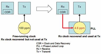
Figure 3. CS VS Sync-E
The above Figure 3 illustrates how the CE will convert into Sync-E. Using Clock and Data Recovery method (CDR) the transmit pulse reaches receiver physical layer. In Ethernet architecture, preamble has important role. With defined preamble the income bit streams were lock into defined receiver and State of Frame Delimiter (SFD) indicates the encapsulated data. The following Figure 4 shows the preamble and SFD in Ethernet frame.

Figure 4. Ethernet frame format
This normal frame structure allows the receiver to receive exact information without any policy of synchronization. Primary Reference Check (PRC) inclusion in physical layer leads to high accuracy frequency reference. This inclusion is enough to get the accuracy of 4.6 ppm (well ahead than CE) as defined by ITU. This accuracy was similar to SDH. The following figure 5 shows timing in synchronous Ethernet.
Figure 5. Clock introduction and recovery in Ethernet structure
The benefit with this method is that the Ethernet timing paths were unaffected at physical layer [10]. In this process if any incoming jitters occurred, they were removed by PLL before pass the information to transmitter. Sync-E is suitable to the technologies of 100Mbps, 1000Mbps and 10Gbps, below 10 Mbps, physical layer is not used for Sync-E [11, 12].
100BASE-TX/FX Implementation
The Figure 6 shows the reference model of 100BASE-TX/FX.
As shown in the Figure 6, the physical layer should connect between Media Independent Interface (MII)/ Gigabit Media Independent Interface (GMII) and Medium Dependent Interface (MDI).
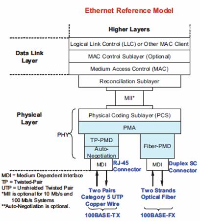
Figure 6. 100BASE-TX/FX
It is also observed from Figure 6 that, MDI acts as an interface between Physical Medium Dependent (PMD) and Media. PMD will take signal from Physical Medium Attachment (PMA) and change it to optical signal. PMA is connected with Physical Coding Sub-layer (PCS) via Independent media interface. This PCS layer should act in synchronized way with Medium Access Control (MAC).
100BASE-TX/FX Physical layer overview
TX module will operate on 2 pairs of category 5 cable which has 100 meters long and FX will run on 2 individual fiber cables and uses 1300nm wavelength [13, 14]. If FX is operated under half duplex mode, it will cover 500m and in full duplex, it will cover 2 Kilometres (Kms). The MAC protocol at this level will define the function of error detection, transmitting time and other functions. The physical layer will do the regular operations like Serialization and Decentralization (SERDER), 4B/5B encoding and some low level functions. In 4B/5B encoding process, the physical layer will take 4 bits as input from MII and transmit 5 bits as output. This output bits transmitted serially on the medium via fiber with specifications of 125MHz frequency and 100Mbps data rate. This data rates may affect Unshielded Twisted Pair (UTP) due to Radio Frequency Interference (RFI) and Electromagnetic Interference (EMI). Hence, regular set up of 10 BASE is not sufficient for best outcome. This is possible through 100 BASE. The following Table 3 shows the translation of 4 bits to 5 bits [15].
Table 3. 4b/5b Encoding
|
Value |
Definition |
|
|
0 |
11110 |
Data 0 |
|
1 |
01001 |
Data 1 |
|
2 |
10100 |
Data 2 |
|
3 |
10101 |
Data 3 |
|
4 |
01010 |
Data 4 |
|
5 |
01011 |
Data 5 |
|
6 |
01110 |
Data 6 |
|
7 |
01111 |
Data 7 |
|
8 |
10010 |
Data 8 |
|
9 |
10011 |
Data 9 |
|
A |
10110 |
Data A |
|
B |
10111 |
Data B |
|
C |
11010 |
Data C |
|
D |
11011 |
Data D |
|
E |
11100 |
Data E |
|
F |
11101 |
Data F |
|
I |
11111 |
IDLE |
|
J |
11000 |
SSD 1 |
|
K |
10001 |
SSD 2 |
|
T |
01101 |
ESD 1 |
|
R |
00111 |
ESD 2 |
|
H |
00100 |
Error |
Previously generated 5 bits data is scrambled (Table 3). The transmitter and receiver should be in lock state. So, receiver can descramble the message at receiver side. This process helps in reduction of spectral content. To reduce spectral content further, apply the Multi Level Transmit (MLT) at level 3. These two applications i.e. Scrambling and MLT reduced the frequency to 31.25 MHz from 100 MHz the following Figure 7 shows the transceiver architecture of 100BASE-TX/FX [16].
Implementation of 4B/5B encoding and decoding, scrambling and descrambling and serialize & de-serialized was also shown in Figure 7.

Figure 7. Transceiver architecture of 100BASE-TX/FX
Physical layer timing and Interference types
Ethernet was considered as interface between MAC layer and media side. The following Figure 8 shows MII interface. MII has 18 pins. Figure 9 represents the MII pin structure. From the Figure 9, it is clear that it has 7 transmit, 7 receive, 2 status bar signals and 2 interface links. It can operate effectively at 10Mbps and with some limitations, it can also be implemented at 100 Mbps. Transmit path [3:0] and its clock cycle, receive path [0:3] and its clock cycle should operate synchronously. In Sync-E, MII is used as interface, but providing reference signal and recovering it again from interface is a challenging task. In Sync-E, clock signal should provide to upstream interference and it should collect at downstream interference. Then it can clean up and joined to downstream links. Reduced silicon geometry of current MII interface is called as Reduced MII (RMII). RMII will convert 16 pin MII (it has 18 pins originally, 2 management interface ports were normally not considering) into 6 pin MII over Xilinx 10/100 Mbps Ethernet MAC. The only considerable drawback in RMII was design and maintenance of elasticity buffer in receiver [17].
Figure 8. MII Interface between PCS and MAC
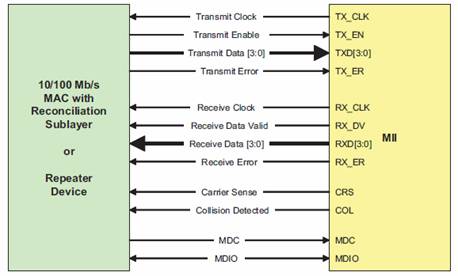
Figure 9. PIN structure of MII
RMII will operate in synchronous format. It takes same clock cycle for both transmit and receive paths as the switch. It can operate at 50 MHz, so that data and control paths were reduced which results pin usage reduction. 50 MHz reference signal acts as a synchronous clock for transmit, receive and control interfaces. Reference clock (REF_CLK) will be given externally and it can provide timing between CRS_DV, RXD, TX_EN and TXD.
The following Figure 10 shows the RMII Pin structure.
Figure 10. RMII Reconciliation layer structure
50 MHz of reference clock was provided externally as shown in Figure 10 by MAC layer. If physical layer is driven by external reference clock which is attached to any one of the pins, RMII structure internally generates 50 MHz only as a reference clock. RMII is used as chip to chip interconnect in this condition; hence, TX_CLK was driven by REF_CLK and it is traceable to reference clock, which intern called as Primary Reference Check (PRC). In non Sync-E applications, RX_CLK has no idea about TX_CLK.
Conclusion
This paper focused on the process of Synchronous Ethernet and its implementation possibilities. In the conventional transmission technique, PLL is used to reduce the timing constraints to 4-5 ppm. In this paper, 100 Base-Tx/Fx implementation was explained with the aid of physical layer modeling and timing architectures. Importance of MII and RMII was analyzed in the operation of Sync-E. RMII implementation clearly explained about the synchronization between transmitted clock and received clock. In future, all interface hurdles should be avoided between physical layer and MAC layer to make real implementation of Sync-E.
References
1. IEEE Standard for Information Technology-Specific Requirements Part 3: Carrier Sense Multiple Access with Collision Detection (CMSA/CD), Access Method and Physical Layer Specifications, IEEE 802.3-2008.
2. Draft Standard for Local and Metropolitan Area Networks - Timing and Synchronization for Time-Sensitive Applications in Bridged Local Area Networks, IEEE P802.1AS/D7.6, Nov. 2010.
3. Seetaiah Kilaru, Aditya Gali, Improving Quality of Service of Femto Cell Using Optimum Location Identification, IJCNIS, 2015, 7(10), p. 35-41.
4. ITU-T Recommendation G.707/Y.1322: Network node interface for the synchronous digital hierarchy ([G707]), Oct. 2000.
5. D. Mills, Network time protocol (version 3) specification, Implementation and analysis, IETF RFC 1305, Mar. 1992.
6. Carbone P., Low complexity UWB radios for precise wireless sensor network synchronization, IEEE Trans. Instrum. Meas., 2013, 62, p. 2538-2548.
7. IEEE Standard for a Precision Clock Synchronization Protocol for Networked Measurement and Control Systems, IEEE 1588-2008.
8. ITU-T. Recommendation G.825: The control of jitter and wander within digital networks which are based on the synchronous digital hierarchy (SDH).
9. ITU-T Recommendation G.783: Characteristics of SDH equipment functional blocks ([G783]), Oct. 2000.
10. Exel R., Receiver design for time-based ranging with IEEE 802.11b signals, Int. J. Navigat. Observat., 2012, 2012, Article ID 743625.
11. ITU-T. Recommendation G.824: The control of jitter and wander within digital networks which are based on the 1544 kbit/s hierarchy.
12. Yoon C., Cha H., Experimental analysis of IEEE 802.15.4a CSS ranging and its implications, Computational Communication, 2011, 34(11), p. 1361-1374.
13. Kilaru S., Public Safety Communication using Relay Node in LTE-Advanced Technology, International Journal of Engineering Research and Technology, 2013, 2(11), p. 1767-1772.
14. Kilaru S., Prasad Y. A., Kiran K. S., Chandra N. S., Design and Analysis of Heterogenious Networks, International Journal of Applied Engineering Research, 2014, 9(17), p. 4201-4208.
15. ITU-T. Recommendation G.823: The control of jitter and wander within digital networks which are based on the 2048 kbit/s hierarchy.
16. American National Standard for Telecommunications, Synchronization Network Architecture, ANSI T1.TR.81.
17. ITU-T. Recommendation G.803: Architecture of transport networks based on the synchronous digital hierarchy (SDH).