Split-phase motor running as capacitor starts motor and as capacitor run motor
Yahaya Asizehi ENESI*, Jacob TSADO, Mark NWOHU, Usman Abraham USMAN,
Odu Ayo IMORU
Department of
Electrical and Electronics Engineering,
E-mail(*): enesi.asizehi@futminna.edu.ng
*Corresponding author, phone: 08035671462
Received: May 11, 2016
/ Accepted:
Abstract
In this paper, the input parameters of a single phase split-phase induction motor is taken to investigate and to study the output performance characteristics of capacitor start and capacitor run induction motor. The value of these input parameters are used in the design characteristics of capacitor run and capacitor start motor with each motor connected to rated or standard capacitor in series with auxiliary winding or starting winding respectively for the normal operational condition. The magnitude of capacitor that will develop maximum torque in capacitor start motor and capacitor run motor are investigated and determined by simulation. Each of these capacitors is connected to the auxiliary winding of split-phase motor thereby transforming it into capacitor start or capacitor run motor. The starting current and starting torque of the split-phase motor (SPM), capacitor run motor (CRM) and capacitor star motor (CSM) are compared for their suitability in their operational performance and applications.
Keywords
Auxiliary winding; Capacitor start motor; Capacitor run motor; Maximum torque; Split-phase motor; Standard capacitor; Starting current; Starting torque
Introduction
The split-phase motor has both main winding and auxiliary winding and these windings are displaced by 90 electrical degree [1, 2]. Single phase capacitor motor can be used for driving pumps, lower power fans, refrigerators, drills, washing machines and compressors [3, 4]. The split-phase induction motor is investigated through MATLAB normal running operation and at maximum torque by the addition of appropriate value of resitance connected to the starting winding. The input parameters of the single phase split-phase induction motor is used as input data to capacitor start-motor and capacitor run motor which are further investigated to run at maximum torque respectively through the gradual addition of the value of capacitor until motor (capacitor start and capacitor run) develop maximum torque. The starting current and the starting torque of each motor is investigated by simulation. The effect of the starting current and the starting torque of the split-phase motor, capacitor-start motor and the capacitor-run motor through the characteristics are displayed by MATLAB. The study of these performance characteristics enable one to know the areas of applications of each motor. The study of the single phase motors which are low power factor machines becomes necessary because of their applications in domestic, commercial and industrial purposes. In [5], there was investigation on an effective model of single phase induction motor with an adjustable switching capacitor. For purpose of understanding, the winding diagrams are drawn for two single phase motors with different number of slots. In [6], capacitors are varied based on torque developed in order to determine the capacitor motor’s maximum efficiency. Researchers such as Mahdi Alshamasin also investigated the optimal performance of single phase capacitor run induction motor [7]. The capacitor versus efficiency of permanent split capacitor (PSC) is also investigated by MATLAB and determined in [8]. Single phase motors are not self-starting because they do not produce rotating magnetic field. Single phase motors are classified as single phase induction motors (resistant-start or split-phase, capacitor start, capacitor run and shaded pole), single phase synchronous motors (reluctance and hysteresis motor) and single phase series or universal motor [9]. The induction motor type of motors have squirrel cage rotors and a single phase distributed stator winding. Using double revolving theory [10], when the rotor is at standstill and the stator winding is connected to single phase ac power supply, a pulsating magnetomotove force (mmf) and a pulsating magnetic flux Φs is established in the axis of the stator winding. This flux induces current in the rotor circuit by transformer action which results in the production of the pulsating magnetic flux Φr along axis of the stator flux Φs. According to Lenz’s law, the two fluxes oppose each other. The angle between these fluxes is zero and no starting torque will be developed. When the rotor is in running conditions either by spinning the rotor or by using auxiliary circuit, the motor can develop torque. A pulsating field is equivalent to the combination of two rotating magnetic fields of half the magnitude but which is rotating at the same synchronous speed in opposite directions. Some characteristics of single phase induction motors are investigated in [11]. The pulsating produces no torque but produces a humming effect and makes the motor noisier than poly-phase motors. The effect of this pulsating torque can be minimized by using elastic mounting or rubber pads.
The aim of this research is to study the starting current and starting torque of the capacitor start motor and capacitor run motor at the value of capacitor that is connected each to their auxiliary winding to develop maximum torque using the input parameters of the split-phase motor. We want to establish the advantage of one motor over the others. Motor running at low starting current at maximum torque will be suitable for any applications.
Material and method
The input data of a single phase split-phase induction motor are collected from laboratory for the purpose of investigation. This is achieved by using the data through the mathematical expressions for the purpose of simulation in order to obtain the desired result. The input parameters are given in Table 1.
Table 1. Input parameters
|
Symbol |
Quantity |
Input values |
|
Vm=Va |
Input phase voltage to main and auxiliary winding |
120V |
|
RIm |
Main winding resistance |
1.6Ω |
|
X1m |
Main winding reactance |
2.5Ω |
|
R1a |
Auxiliary winding resistance |
2.5Ω |
|
X1a |
Auxiliary winding reactance |
2.5Ω |
|
R2’ |
Auxiliary resistance referred to main winding |
1Ω |
|
X2’ |
Auxiliary reactance referred to main winding |
1.6Ω |
|
Xmag |
Magnetisation reactance |
42Ω |
|
f |
Frequency |
50Hz |
|
C1 |
Capacitor for capacitor start motor |
300µF |
|
C2 |
Capacitor for capacitor run motor |
30 µF |
Algorithm
Algorithm is or are series of steps taken in order to obtain desired results of any problem. First SPM, CRM and CSM characteristics are investigated on normal operations. SPM input data are later transformed to the design characteristics of capacitor run and capacitor start motor. The magnitude of capacitor that develop maximum torque in capacitor start motor and capacitor run motor are investigated and determined by simulation.
Stator winding diagrams
The winding techniques of a single phase motor are shown in both Figure 1 and 2. These are not results but illustrations. The winding diagrams of single phase motors are made up of 16 and 24 slots respectively with each of 4 poles shown in Figure 1 and 2.

Figure1. Single phase winding with 16 slots and 4 poles

Figure 2. Single phase winding with 24 slots and 4 poles
Split-phase circuit diagram
The circuit diagram of a split-phase motor is shown in Figure 3.

Figure 3. Split-phase motor
The running winding has large size of wire with low resistance and high inductive reactance, as a result, the current of the running winding lags behind the voltage to approximately 90° electrical degrees while the starting winding has low wire gauge or low wire size with high resistance and low inductive reactance, and due to low wire size, the high starting current known as the rocked rotor current can cause motor to overheat resulting in the failure of the starting winding.
The current of the starting winding leads the current of the running winding by approximately 30° electrical degrees as shown in Figure 4.

Figure 4. Vector diagram of split phase motor
The torque developed by this motor is directly proportional to the size of an angle between the running and starting winding currents.
The direction of rotation of the motor is normally reversed by interchanging the leads of the starting winding.
The speed regulation of the motor varies from 2 to 5% between no-load and the full-load and the motor moves with constant speed like three phase induction motor.
The Equivalent circuit of split phase motor at standstill condition is shown in Figure 5.

Figure 5. Equivalent circuit of split-phase motor at standstill condition
Figure 5 left is the Equivalent circuit of the main winding at standstill while Figure 5 right is the Equivalent circuit of the starting or auxiliary winding at standstill condition.
Figure 6 shows the Equivalent circuit of the main winding of split phase motor at running condition.

Figure
6. Equivalent circuit of
Capacitor star motor
The circuit diagram of capacitor start motor is shown in Figure 7, a capacitor is connected in series with the starting winding (larger wire size than the split phase motor) in order to provide higher the starting torque than that obtained from split phase motor and also to limits the starting surge current to a value lower than that of the split phase motor.

Figure 7. Capacitor start
The capacitor does not improve the power factor of the motor but improve the starting torque. The starting torque depends on the angle between the starting current and the running winding and this angle is larger in a capacitor start, induction run motor than in a split phase motor, and a high starting torque is obtained with low starting current. Figure 7 is the vector diagram of a capacitor start, induction run motor.
The motor is used where a strong starting torque is needed such as in the compressors, vacuum pumps, high pressure water pumps and oil burners. The vector diagram of capacitor start motor is shown in Figure 8.

Figure 8. Vector diagram of capacitor start, induction run motor
Figure 9 shows the Equivalent circuit of capacitor start motor at standstill condition. Figure 9(a) is the main winding circuit at standstill condition while figure 9(b) is the auxiliary winding circuit at standstill condition. At standstill condition, the slip is zero.

Figure 9. Equivalent circuit of capacitor start motor at standstill condition

Figure 10. Equivalent circuit of main winding of capacitor start motor at running condition
The Equivalent circuit of the main winding of capacitor start motor at running condition is shown in Figure 10. At forward rotating field, the slip is indicated as s and when the field rotates backward, the slip is indicated as (2-s).
Capacitor run motor
In Figure 11, a capacitor is connected in series with the starting winding which is not disconnected by any switch when the speed rises up to 75% but remain in circuit during the starting and running operation.

Figure11. Capacitor start, capacitor run motor with one capacitor
This type of motor is quiet in operation and it is used in oil burners, fans, wood working and metal working machines.
Capacitor start, capacitor run motor with two capacitors
The capacitor start, capacitor run motor with two capacitors has a high starting torque with good speed regulation and a power factor of nearly 100 per cent at the rated load.
This type of motor is used as fans, compressors and in refrigerator units. The circuit diagram is shown in Figure 12. Figure 13 shows the Equivalent circuit of capacitor run induction motor at standstill condition.

Figure12. Capacitor start, capacitor run motor with two capacitors

Figure 13. Equivalent circuit of a capacitor run induction motor at standstill condition
Figure 13(a) is the Equivalent circuit of the main winding of the capacitor run motor while Figure 13(b) shows the Equivalent circuit of the auxiliary winding of the capacitor run motor. The Equivalent circuit of capacitor run induction motor at running condition is shown in Figure 14.

Figure 14. Equivalent circuits of a capacitor run induction motor at running condition
Mathematical analysis at no-load and full load
At no-load
The leakage impedance of the main and auxiliary winding is given by:
|
|
(1) |
The leakage impedance of the auxiliary winding is given by:
|
|
(2) |
The ration of the number of turns of the auxiliary winding to the number of turns of the main windings is given by:
|
|
(3) |
The value of the external capacitor to be inserted in series with the auxiliary winding to obtain maximum starting torque is given by:
|
|
(4) |

The capacitive reactance is given by:
|
|
(5) |
The capacitance impedance connected in series with the auxiliary winding is given by:
|
|
(6) |
The input voltage is the same across the main and auxiliary winding of the motor and this is given by:
|
|
(7) |
The forward impedance at no-load is given by:
|
|
(8) |
The backward resistance is equal to forward resistance of the motor at starting and this is expressed by:
|
|
(9) |
The impedance of the main winding is given by:
|
|
(10) |
The impedance of the auxiliary winding of split phase motor is given by:
|
|
(11) |
For capacitor start motor and capacitor run motor, the impedance of the auxiliary winding is given by:
|
|
(12) |
The main winding current for split phase and capacitor start motor is given by:
|
|
(13) |
The auxiliary current of a capacitor run motor is given by:
|
|
(14) |

The main current of the capacitor run motor is given by:
|
|
(15) |
The auxiliary current of split phase and capacitor start motor is given by:
|
|
(16) |
The starting current of single phase motor
|
|
(17) |
The starting torque developed by the motor is given by:
|
|
(18) |
where ![]() and
and ![]()
At full load slip
The forward impedance at full load slip:
|
|
(19) |
The backward impedance at full load slip:
|
|
(20) |
The input Impedance of single phase motor is given as:
|
|
(21) |
The input current of the motor running on full load:
|
|
(22) |
The torque developed at rated speed is given by:
|
|
(23) |
The input power to the motor is:
|
|
(24) |
The sum of the torque developed at rated speed and the starting torque is given by:
|
|
(25) |
Results and discussion
Table 2 shows the value of various capacitors inserted in the starting (auxiliary) winding of a capacitor run motor (CRM) to develop the respective value of torque during the normal operation of the motor.
Table 2. Capacitor and Torque values of CRM
|
Capacitor (μF) |
400 |
500 |
525 |
550 |
600 |
620 |
625 |
630 |
|
T (N-m) |
6.56 |
8.6 |
8.95 |
9.22 |
9.54 |
9.58 |
9.58 |
9.57 |
|
Capacitor (μF) |
640 |
650 |
700 |
725 |
750 |
775 |
800 |
|
|
T(N-m) |
9.58 |
9.57 |
9.39 |
9.24 |
9.06 |
8.87 |
8.67 |
|
In Table 3, the torques developed by each capacitor start moror at various capacitor is shown at its normal operation.
Table 3. Capacitor and Torque values of CSM
|
Capacitor (μF) |
600 |
625 |
650 |
700 |
725 |
750 |
775 |
790 |
800 |
|
T (N-m) |
9.32 |
9.62 |
9.82 |
10.2 |
10.3 |
10.35 |
10.37 |
10.36 |
10.34 |
|
Capacitor (μF) |
825 |
850 |
875 |
900 |
925 |
950 |
1000 |
1500 |
|
|
T (N-m) |
10.29 |
10.2 |
10.1 |
9.97 |
9.81 |
9.66 |
9.3 |
5.86 |
|
Table 4 shows the starting current and the starting torque of CRM, SPM and CSM when the input data of SPM is used as input parameters for CRM and CSM with the connection of capacitors whose values are 30 and 300 microfarad to the starting winding of CRM and CSM respectively.
Table 4. Starting current and starting Torque of CRM, SPM and CSM
|
Motor types |
CRM |
SPM |
CSM |
|
Tst (N-m) |
0.19 |
0.96 |
4.14 |
|
Ist (A) |
24.59 |
47.66 |
41.32 |
CRM has both the lowest starting current and the lowest starting torque compared with CSM and SPM.
In Table 5, CRM developed the lowest starting current and highest starting torque at maximum torque using various capacitors in CRM and CSM and investigated by MATLAB to produce maximum torque.
Table 5. Starting current and starting Torque of CRM, SPM and CSM at maximum Torque
|
Motor types |
CRM |
SPM |
CSM |
|
Tst (N-m) |
10.36 |
2.04 |
9.58 |
|
Ist (A) |
34.84 |
38.14 |
58.61 |
The Torque versus speed characteristics of SPM and CSM are shown in Figure 15. It is cleared that the starting torque of CSM is more than the starting torque of SPM. Any of the motors can be applicable depending on the starting torque of a load.
Figure 15. Torque versus motor speed characteristic of SPM and CSM
Figure 16 shows the Torque versus motor speed of SPM and CRM. SPM has a higher starting torque. The Torque versus motor speed characteristics of CSM and CRM are shown in Figure 17. The starting torque of CSM is higher than the starting torque of CRM. The Torque versus capacitor characteristics of a capacitor run motor and a capacitor start motor under investigation by MATLAB is shown in Figure 18. This it is to determine the value of capacitor connected in series with the starting winding of CRM and CSM each that will develop maximum torque in each motor. At point of intersection of the K, both motor develop the same torque with the same magnitude of the capacitor.
Figure16. Torque versus speed characteristic of SPM and CRM
Figure 17. Torque versus motor speed characteristic of CSM and CRM
Figure18. Torque versus capacitor characteristic
Figure 19 shows the Torque versus motor speed characteristics of CRM, CSM and SPM of each of them is operating at maximum torque in the absence of the centrifugal switch.
Figure 19. Torque versus motor speed characteristic of CRM, CSM and SPM
The CRM has the highest starting torque and followed by the CSM. SPM has the least starting torque. All these are subject to the initial given input data from SPM used as input data for the operating conditions for CRM and CSM. When the value of 300 microfarad capacitor is connected on each of CRM and CSM, the Torque versus motor speed characteristic is shown in Figure 20. The Torque versus motor speed characteristics of each motor is shown in Figure 21.
Figure 20. Torque versus motor speed characteristic of CSM and CRM with C=300μF each
Figure 21. Torque versus motor speed characteristic of CRM and CSM with C=625μF each
For Figure 20 the capacitor start motor has a higher starting torque than the capacitor run motor. Any of the motors can be applied depending on the area each is needed. There is further investigation by MATLAB simulation as value of the capacitor connected each in series with the starting winding of CRM and CSM is increased from 300 microfarad to 625 microfarad capacitor. At this value of capacitor, each motor develops the same starting torque.
The value of capacitor needed for CRM to develop the highest torque is 800 microfarad. This value is now connected each in series with their starting winding and the torque produced by each is shown in Figure 22.
Figure 22. Torque versus motor speed characteristic of CRM and CSM with C=800μF each
It is obvious that CRM produces the higher starting torque than the CSM. The starting current versus the starting torque characteristics of CRM, SPM and CSM are shown in Figure 23. If each motor is to operate in normal (N) torque or serves as original input data, the starting current is indicated as N, and as each motor has to be operated at maximum (M) torque, their starting current are indicated each by M.
Figure 23 shows the starting current and the starting torque of each motor in a bar form for further illustration. The advantages of CRM over the CSM and SPM at the value of 800 microfarads, is its ability to develop the highest starting torque and lowest starting current. This is desirable for high starting torque load. The same wire size for each motor cannot be used as each has variable starting current which is a limitation that will be further investigated in our next research.
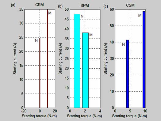
Figure 23. Starting current versus starting torque characteristic of CRM, SPM and CSM
Conclusions
The maximum capacitor that makes each of the motor to develop maximum torque is determined. Investigation of input parameters of each motor through MATLAB simulations shows that CRM develops the highest starting torque and lowest starting current.
Motor with higher starting current prevents longer life span, causes heat losses and lamination breakdown, thereby decreasing its efficiency and should not be desirable
Acknowledgement
I acknowledge the chief Technologist, Isah Idoko in Electrical and Electronics workshop for providing materials and time in carrying out this research work.
References
1. Sujay Sarkar, Subhro Paul, Satyajit Samaddar, Surojit Sarkar, Pradip Kumar Saha, Gautam, Kumar Pandar, Modelling, Analysis and Simulation of Split phase Type of Single Phase Induction Motor, Internal Journal of Advanced Research in Electrical, Electronics and Instrumentation Engineering, 2013, 2(5), p. 1683-1690.
2. Rakesh Parekh, An Induction Motor Fundamentals, Microchip Technology Inc., 2003, p. 1-24
3. Alexander L., Krzysztof M., Analysis of a single-phase Induction Motor operating at two power line frequencies, Archives of Electrical Engineering, 2012, 61(2), p. 252-266.
4. Mera R., Câmpeanu R., Experimental
Investigation of the capacitor influence on the Single Phase Induction Motor,
Latest Advances in Information Sciences, Circuits and Systems.
5. Sedat S., Mehmet O., Bilal G., Modeling and Simulation of a single phase induction motor with adjustable switch capacitor, 9th International conference on power Electronics and power control, EPE-PEMC, Kosice, 2000, p. 5-1 to 5-5.
6. Ali
A., Razzaq Al - Tahir, Single,
Phase Induction Motor,
7. Mahdi Salman Alshamasin, Optimization of the performance of single phase capacitor-run induction motor, American Journal of Applied Sciences, 2009, p.745-751.
8. Enesi A.Y., Tola J., James G. A., Eugene O. A., Permanent Split Capacitor (PSC) Alternating Current Induction Motor, Leonardo Electronic Journal of Practices and Technologies, 2015, 26, p.175-188.
9. Agarwal R. K., Principles of Electrical Machine Design, Delhi, S .K. Kataria & Sons, India, 2005.
10. Enesi A. Y., Performance Characteristics and Double Revolving Theory of Single Phase Induction Motor, Leonardo Journal of Sciences, 2013, p. 1-12.
11. Lab-volt ltd., Single-phase Induction Motor, Printed in Canada, First Edition, February 2013, p. 7-9.