Engineering, Environment
A new application of neural network technique to sensorless speed identification of induction motor
Mohamed MOSTEFAI1, Yahia MILOUD2, Abdullah MILOUDI3
1 Université de Saida, BP 138, En–Nasr, Saida 20000, Algérie
E-mail(s): 1 mostefaimed@yahoo.fr; 2 amiloudidz@yahoo.fr; 3 miloudyahiadz@yahoo.fr
* Corresponding author, phone/ fax: 00(213) 48 477730
Received: August 7, 2016 / Accepted: November 30, 2016 / Published: December 30, 2016
Abstract
A new application of neural network technique to sensorless speed identification of scalar-controlled induction motor is implemented in this paper. The neural network estimates the rotor speed through stator measurements and nominal settings of the motor. By changing the motor parameters, the neural network can estimate the speed of another motor. We evaluated our approach based on the speed response and load disturbance effects on two different motors. The test results demonstrate the feasibility of the method.
Keywords
Neural network; Scalar control; Induction motor drives; Speed sensorless
Introduction
In recent years many methods have been developed which allow eliminating speed sensors, because in many industrial applications it is neither possible nor desirable to use a mechanical sensors.
In [[1]-[4]] rotor speed is estimated through identification and estimation of slot harmonics frequencies, present in the acquired current signal. Works [1] and [[5]-[9]] study the speed estimation methods for the field oriented control of induction machine based on model reference adaptive system (MRAS) technique with the Popov's hyper stability.
The variation of the rotor resistance could distort the decoupling between flux and torque and, thereby, lead to the deterioration in performance. To overcome these problems [[10]] propose to estimate speed and rotor resistance of induction motor using an extended Kalman filter (EKF), while [1], [8] and [[11]-[14]] resume other technics of sensorless vector control of induction machine.
In the recent past, artificial neural networks (ANN) have found widespread usage in function approximation [[15]]. It has been shown that theoretically a three layer ANN can approximate any nonlinear function, provided the function is continuous and non-singular [15]. This property has been exploited by a few researchers working in the induction motor drives area [[16]-[20]].
Neural networks have the advantages of fast parallel computation and fault tolerance capability. In neural network applications, the speed response under rated voltage and frequency can be first collected to train the designated neural networks. Once networks have been well trained, the required torque corresponding to the speed command can be obtained.
In this paper, a new method of applying neural network techniques to achieve the sensorless speed identification of scalar-controlled induction drives is proposed. This proposed scheme applies neural computation to find the nonlinear relationships between the speed, stator voltages, stator currents and nominal settings of two different motors.
Material and method
Principle of the method
It is necessary to design a right structure of ANN and it is also important to determine such inputs to ANN, which are available and able to estimate rotor speed of induction motor (IM). A recommended method does not exist for determination of ANN structure, so the final ANN structure was designed by means of trial and error. The neural network configuration is 8 inputs neurons assigned for stator measurements(usα(k),usα(k-1),usβ(k), usβ(k-1), isα(k), isα(k-1),isβ(k), isβ(k-1)), 3 inputs neurons for nominal settings of the motor( nominal speed, nominal current and nominal power ) and one output neuron for the estimated rotor speed. The activation functions in hidden layer are tansigmoids and the output neuron as linear activation function. Figure 1 shows the neural network structure.
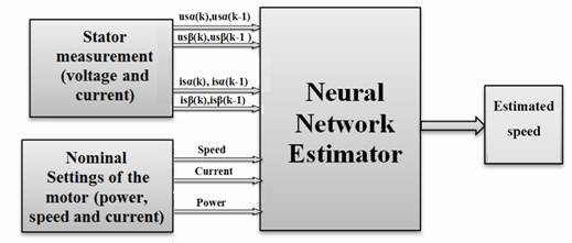
Figure 1. Neural network structure
The network was simulated in Matlab and was implemented in the real drive system. For implementation of neural speed estimator on the real electrical drive it is necessary to obtain such training data, which determine the desired behaviour of artificial neural network. The training data set was obtained from the real control induction motor drive. The testing data set is different from the training data set. In this way, the generalization of trained neural network can be validated.
The training phase is performed in Matlab using Levenberg-Marquardt algorithm [[21]]. Figure 2 shows the bloc diagram of the neural network training method.
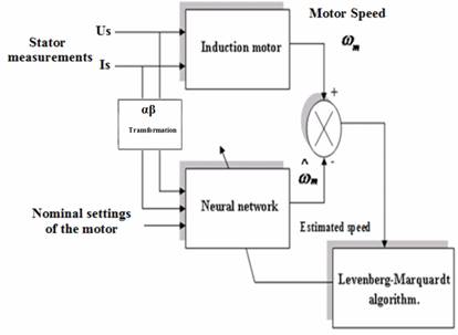
Figure 2. Block diagram of the neural network training method
Once a network has been structured for a particular application, that network is ready to be trained. To start this process the initial weights are chosen randomly. Then, the training, or learning, begins. The network then processes the inputs and compares its resulting outputs against the desired outputs. Errors are then propagated back through the system, causing the system to adjust the weights which control the network [[22]-[24]].
System Descriptions
To accurately test the effectiveness
of the estimated speed method based on ANN speed estimation, a closed
loop control system is to be implemented. This control system will calculate
the speed of the motor and compare it to the reference speed ![]() . A
three-phase inverter will be used to alter the stator currents to enable the
speed to be changed.
. A
three-phase inverter will be used to alter the stator currents to enable the
speed to be changed.
The three-axis model is transformed to a two-axis model
and then all the analysis is done in the two axes. The actual speed ![]() is
measured by tacho for testing only. A block diagram of the control system is
shown on the figure 3.
is
measured by tacho for testing only. A block diagram of the control system is
shown on the figure 3.
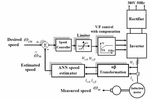
Figure 3. Block diagram of the control system
The characteristic is defined by the boost voltage (the boost voltage V0 is required to run the motor properly at low speeds) and the base point of the motor. Below the base point, the motor operates at optimum excitation due to the constant V/f ratio. Above this point, the motor operates under-excited because of the voltage limit [[25]28].
Hardware Configuration
The experimental setup is illustrated in Figure 4. The induction motor (IM) was fed by a frequency converter controlled by pc card interface board. The switching frequency and the sampling frequency were 3 kHz. The controllers and the estimators were discredited. The gains and offsets of the current and dc voltage measurements were tuned carefully. The parameters of the two motors are given in Table 1 and Table 2.
Table 1. Parameters of the first induction motor
|
Nominal power (kW) |
Nominal voltage and current (V/A) |
Nominal speed (rpm) |
Nominal frequency (Hz) |
|
1 |
380V/2.2A |
2880 |
50 |
Table 2 . Parameters of the second induction motor
|
Nominal power (kW) |
Nominal voltage and current (V/A) |
Nominal speed (rpm) |
Nominal frequency (Hz) |
|
1.5 |
380V/3.7A |
1500 |
50 |
In practice a low pas filter (LPF) is used to eliminate the high harmonics from the measured stator voltage, due to the PWM operation of the inverter. The stator current has to be consequently proceeded by the same LPF In order to ensure the correct phase shift between the stator current and voltage.
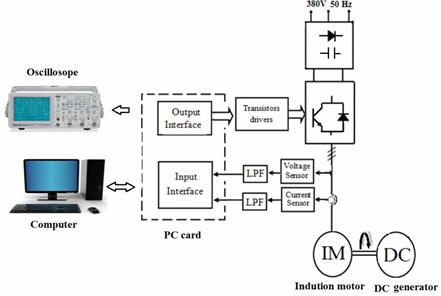
Figure 4. Configuration of the experimental system
In our configuration, the LPF is realized by analogue. The speed closed-loop control is characterized by the estimated of the actual motor speed. This information is compared with the reference speed while the error signal is generated. The magnitude and polarity of the error signal correspond to the difference between the actual and required speed.
Based on the speed error, the PI controller generates the corrected motor stator frequency to compensate for the error. The DC generator (DC) is used as a load, and the variable resistor box loads the DC generator.
Results and Discussions
Figures 5, 6 and 7 show an example of neural network training data, Figure 5a shows the speed response which serves as the network target.
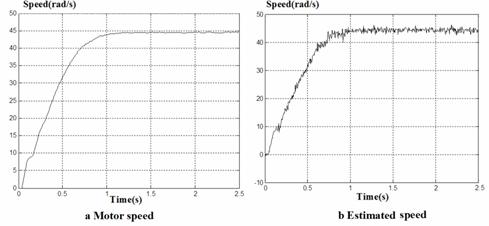
Figure 5. Real and estimated speed using ANN
Figure 6 and figure 7 show the stator measurements (voltage and current) representing the input data for the neural network.
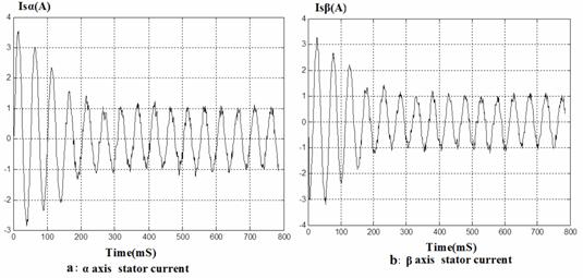
Figure 6. Waveforms of neural network training data (stator current)
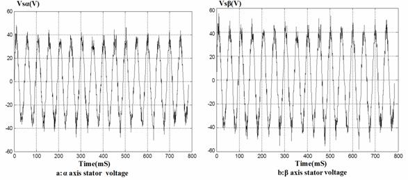
Figure 7. Waveforms of neural network training data (stator voltage)
Various tests were conducted to characterize the performance of the system. The Figure 8a shows the estimated speed and the real rotor speed. Another test is repeated for the second motor by changing simply the motor settings. Figure 8b shows the estimated speed and the real rotor speed for the second motor.
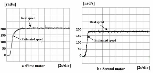
Figure 8. Real rotor speed and estimated rotor speed with no load applied
As shown in these figures, the estimated speed tracks the real rotor speed. Moreover, the estimated speed is not affected by the load torque as shown on Figure 9a and Figure 9b for the two motors.
Figure 10a and Figure 10b shows the performance of the speed control using the various speed commands.
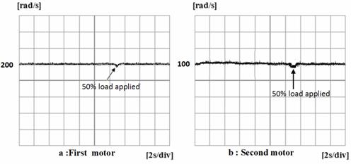
Figure 9. Real rotor speed and estimated rotor speed with 50% load applied in steady state
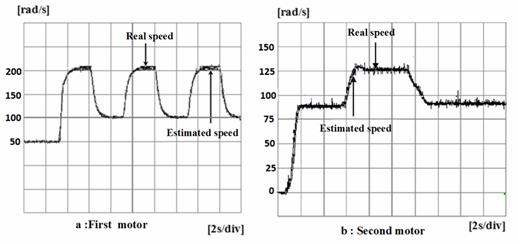
Figure 10. Speed waveform of sensorless scalar controlled induction machine with various speed commands
The result indicated that the system had a good accuracy of speed for the two motors.
Conclusions
A new neural network based identification of speed-sensorless Volt per Hertz controlled induction drives was presented. The speed estimator is based on a feed forward neural network. The induction machine is a nonlinear multivariable dynamic system with parameters that vary with temperature, saturation and operating point. Considering that neural networks are capable of handling time varying nonlinearities due to their own nonlinear nature, they are suitable for application in induction machine systems. During training phase the neural network does not have any training patterns, which represent a behaviour of the drive with load, but the ANN-based speed estimator works correctly even in such situations and the difference between the real and estimated rotor speed is minimal.
References