Physics, Chemistry, Biology
Characterization of Abaji clay deposits for refractory applications
Grace Olufunke MATHEW, Seun Samuel OWOEYE*
Department of Glass and Ceramics, Federal Polytechnic, Ado-Ekiti, P.M.B. 5351, Nigeria
Emails: olufunkegrace2012@yahoo.com; *owoeyeseun@yahoo.com
*Corresponding author, phone: +2348064461915
Received: August 5, 2016 / Accepted: August 8, 2016 / Published: December 30, 2016
Abstract
In this research work, Abaji clay deposit in Abuja, Nigeria was investigated to determine its suitability for refractory applications. The clay was sourced from three different locations having Red clay, Pink clay, and White clay; and was labeled samples A, B, and C respectively. The chemical analysis was carried out by X-ray Fluorescence Spectrometry complemented with thermogravimetry while the mineralogical analysis was conducted using X-ray Diffractometer and property tests such as sieve analysis, loss on ignition, shrinkage, porosity, bulk density, plastic index, thermal shock resistance, permanent linear change on re-heating, and refractoriness were carried out using standard techniques. The chemical analysis shows that samples A, B, and C were composed of Silica: 49.98%, 36.89%, and 44.38% respectively; Alumina (Al2O3): 16.39%, 20.12%, and 18.33% respectively. The mineralogical analysis shows the clays are mainly kaolinite and free quartz. The results of the physical tests show that samples A, B, and C have: an apparent porosity of 25.90%, 20.78%, 13.82% respectively; shrinkage of 1.90%, 2.04%, 0.95%; bulk density of 1.58g/cm3, 1.63g/cm3, 1.78g/cm3; thermal shock resistance of 11cycles, 15cycles, 17cycles respectively; while the three samples A, B, and C have the same refractoriness of 1100 °C.
Keywords
Abaji clay deposit; X-ray Fluorescence; X-ray Diffractometer; Kaolinite; Refractoriness; Thermal shock resistance; Shrinkage
Introduction
Refractories are class of ceramic materials which are used for high temperature applications, normally above 1100 °C [1]. They are mostly comprised of naturally occurring oxides with high melting temperature such as Al2O3, SiO2, ZrO, Cr2O3, MgO. Refractories are used almost in every industry where high heat is used, such as cement, chemical, metallurgical, glass tan, ceramic kilns, petrochemicals, steam boilers, and hot stoves [2]. Typical refractory materials include Magnesia, Zirconia, non oxide like Silicon Carbides (SiC), Boron carbide(B4C), Nitrides(Si3N4), Aluminum Nitrides (AlN), and Carbon (graphite and coke).
There is enormous need for refractories in Nigeria industries; for instance, [3] iterated that the Ajaokuta Steel Complex will require about 36,000 tons of refractory bricks on completion for furnace lining while [4] estimated that at full operation capacity, both Ajaokuta Steel Complex and Delta Steel will require 43,503 and 2500 tons/year of fire clay refractories for their activities respectively. In [5] were also reported that Nigeria imported 27 million metric tons of refractories in 1987 indicating the country spends a lot of foreign exchange importing refractories, yet vast deposits of clay abound in Nigeria which can be harnessed and developed to meet our local consumption.
Various researches [2, 6-7] have been carried out on Nigerian clay in order to determine their potential for ceramic, industrial, and refractory applications. [8] Reported in his investigation and concluded that the properties of refractory samples from Onibode, Ara- Ekiti, Ibamajo and Ijoko clays compete excellently with the imported fire clay refractories while in [9] were found that Onibode clay is suitable for the production of refractory bricks which can be utilized for furnace lining. Kankara clay has also been investigated in [10-11] and found to be suitable for use in the preparation of synthetic foundry sand and refractory bricks production respectively. In [12] were also investigated the properties of refractory materials from Kuru, Barkin-ladi, Alkaleri, and Bauchi locations of the country (Nigeria) and found that the clays were suitable for construction of furnace because of their high thermal shock resistance, bulk density, cold crushing strength, and refractory properties.
Owing to the enormous demand of refractories in most metal industries, glass industries, and application where refractories are needed, which in turn has motivated many researchers at various place in Nigeria to analyze our enormous clay deposits in the country in order to determine their suitability in refractory applications.
Therefore, this present research work aims to characterize Abaji clay deposit from Abuja in order to substantiate its utilization in refractory applications.
Material and method
Location of the clay raw material
The raw samples of clay (A, B, and C) were collected from an open mine site at Abuja village, but different locations. Abuja is located in the centre of Nigeria and has a land area of 8000 square kilometers; it is bounded on the North by Kaduna state, on the West by Niger state, on the East and South- East by Nasarawa state, and the South West by Kogi State. It falls within latitude 7°45' and 7°39'. The Abaji is situated in FCT, Nigeria its geographical coordinates are 8°28'0'' north, 6°57'0'' East.
Processing of the collected clay sample
The collected lumps from Abaji were crushed into powder form and soaked in different soaking pit for five days. The soaked clay comes in different colours, pink, red, and white respectively, the clays were later poured on a flat surface for the removal of excess water which took one week. The clays were later oven dried at temperature of 110 °C for water content removal; the dried clays were later crushed to powdery form and sieved with a size of 185 microns.
Sieve analysis
200g of each ground clay samples (A, B, and C) were poured into pre-arranged sieve of 336 µm, 242 µm, 198 µm, 160 µm, and 137 µm, mounted on a mechanical sieve shaker for 30 minutes after which the content of each sieve was weighed. The percentage retained and passed was then calculated for each sample: red, pink, and white clay respectively.
Chemical and mineralogical analyses
The chemical analysis of the clay samples were conducted using X-ray Fluorescence instrument. 1g of each clay sample (A, B, and C) was added to 10g of Lithium tetraborate anhydrous solution as a fluxing agent. The constituents were mixed inside a crucible and heated to 500 °C for 8 minutes before analyzed. The results were completed using thermogravimetry method while the mineralogical composition was determined by X-ray Diffractometer (XRD)
Loss on ignition
2g from each sample clay (A, B, and C) was weighed respectively and poured inside three different crucibles; the crucibles containing each sample clay were placed inside a furnace and heated to temperature of 800 °C for 3 hours, and later cooled in desiccators. The percentage loss on ignition was then calculated using the formula:
Loss on ignition = (W1-W2)/W1 (1)
where W1 = weight of the crucible + weight of the sample before firing and W2 = weight of the crucible + weight of the sample after firing.
Plasticity index
The determination of plastic index for each clay sample (A, B, and C) was carried out using Atterberg Test in accordance with ASTM D423-66. The moisture contents obtained for the liquid limit (LL) and plastic limit (PL) tests were then used to compute the plastic index (PI). The difference between the plastic limit and liquid limit gave the plastic index for each of the clays.
Sample preparation
Dry pressing method was employed for producing the test samples from each sample clay (A, B, and C) respectively using a 10 tons capacity hydraulic press. The clay material was presses inside an iron mould with dimension 110 ´ 110 ´ 10 mm. The produced test samples were oven dried at 110 °C for 5 hours and fired in a furnace at 1200 °C. The fired samples were then allowed to cool gradually inside the furnace overnight.
Firing shrinkage test
The firing shrinkage property of the fired pressed samples were carried out by measuring the dimensional changes that occurred between the dried samples at 110 °C and the fired test pieces at 1200oC according to [2] using the formula:
Firing Shrinkage = (LD - LF)/LD (2)
where LD = Dry dimension and LF = Fired dimension.
Apparent porosity test
The porosity of the fired test samples from each clay materials (A, B, and C) was determined by boiling method as stated by [1]. Test specimen measuring 50 ´ 50 ´ 10 mm was cut and prepared from the fired samples of each clay materials and dried in an oven at 110 °C to obtain a constant weight ‘D’. The specimen was freely suspended in a beaker containing distilled water and boiled for two hours, cooled to room temperature and weighed to obtain weight ‘S’. The specimen was later removed from the water and weighed to obtain a saturated weight ‘W’. The apparent porosity was determined using:
Apparent Porosity = 100·(W-D)/(W-S) (3)
where W = saturated weight, D = dry weight, and S = suspended weight.
Bulk density
The bulk density of the fired test samples from each clay material (A, B, and C) was also determined using the boiling method stated by [1]. Samples of dimension 50 ´ 50 ´ 10 mm was prepared from the fired samples, oven dried at 110 °C, and transferred into a beaker containing distilled water to boil for two hours in order to assist in releasing entrapped air. It was then allowed to soak and the saturated weight void of excess water was taken. The bulk density was afterward determined using:
Bulk Density = ρw·D/(W-S) (4)
where: D = dry weight, W = saturated weight, S = suspended weight, ρw = water density.
Permanent linear change on re-heating
The permanent linear change on re-heating was determined according to ASTM C 201-86 standard as stated by [13]. Samples of 50 ´ 50 ´ 10 mm was cut and prepared from the fired test samples of clay materials A, B, and C respectively. The samples were placed inside a muffle furnace, heated at temperature of about 1000 °C for 5 hours, and cooled inside a dessicator. The permanent linear change on re-heating (PLCR) was determined using:
PLCR = 100·(LA-LB)/LB (5)
where LA = initial length before re-heating and LB = final length after re-heating.
Thermal shock resistance
The ability of a clay material to withstand repeated cycles of heating and cooling before a crack is observed is referred to as thermal shock resistance according to [14]. Samples of dimension 50 ´ 50 ´ 10 mm was cut and prepared from the fired test samples of clay materials A, B, and C respectively. The cut and prepared test pieces were placed inside a muffle furnace and heated to a temperature of 900 °C for 3 hours. The samples were then removed from the furnace using a pair of tong and plunged immediately inside water. The samples were introduced into the furnace again and soaked at that temperature for few minutes before they were taken out again to be plunged inside water. The process was repeated several times until a visible crack was observed on them. The number of cycles before crack was observed and was then noted to be the thermal shock resistance for each sample of A, B, and C clay materials.
Refractoriness
Pyrometric Cone Equivalent (PCE) was employed to test for refractoriness as stated by [15]. Each of the clay materials A, B, and C were used to compose a self-made pyrometric cone of standard composition for 1050 °C, 1100 °C, and 1200 °C as stated by [16] of 1.16 cm base diameter. The cones were placed inside furnace with a monitoring thermocouple and heated to a high temperature above 1200 °C. The cones are closely monitored via the spy hole of the furnace and the temperature at which each cone bent over was noted to be the refractoriness of the clay materials A, B, and C respectively.
Results and Discussion
The sieve analysis results from Table 1 shows that all three clay samples A, B, and C have an average high percentage pass above 80% indicating highly fine clay. This shows that all the clay samples A, B, and C can be well compacted to give good dense bricks.
Table 2 gives the results for the chemical analyses for the clay samples A, B, and C indicating SiO2 and Al2O3 are the predominant constituents followed by CaO.
Table 1. Sieve analysis results
|
Mesh size (µm) |
Sample A (red clay) |
Sample B (pink clay) |
Sample C (white clay) |
|||
|
% RT |
% P |
% RT |
% P |
% RT |
% P |
|
|
336 |
18.28 |
81.72 |
13.50 |
86.50 |
36.00 |
64.00 |
|
242 |
6.98 |
93.02 |
4.22 |
95.78 |
7.41 |
92.59 |
|
198 |
5.65 |
94.35 |
2.91 |
97.09 |
12.83 |
87.17 |
|
160 |
12.33 |
87.67 |
10.00 |
90.00 |
25.00 |
75.00 |
|
137 |
13.50 |
86.50 |
22.50 |
77.50 |
9.13 |
90.87 |
|
%Avg= |
11.35 |
88.65 |
10.63 |
89.37 |
18.07 |
81.93 |
Table 2. Chemical analysis
|
Oxides in Samples |
Sample A (red clay) |
Sample B (pink clay) |
Sample C (white clay) |
|
SiO2 |
49.98 |
36.89 |
44.38 |
|
Al2O3 |
16.39 |
20.12 |
18.33 |
|
Fe2O3 |
2.85 |
10.06 |
5.46 |
|
CaO |
17.08 |
21.80 |
19.29 |
|
MgO |
3.36 |
1.819 |
2.78 |
|
Na2O |
0.030 |
0.034 |
0.045 |
|
K2O |
0.034 |
0.036 |
0.048 |
|
L.O.I |
0.17 |
0.220 |
0.39 |
However, the SiO2 of all the clay samples A, B, and C fall short of standard percentage as stated by [17-18] but they can still be utilized for alumino silicate applications. The alumina contents (16.39%, 20.12%, and 18.33%) of the three samples A, B, and C respectively fall within the range value of 16-29% for high melting clay and alumino silicate as stated by [17-18].
The alumina content therefore is an indicator of clay refractoriness. The loss on ignition (L.O.I) contents of the clay samples A, B, and C are also the lowest value indicating that they can be used as refractory bricks and high melting clay according to [17-18] because the L.O.I is required to be low as stated by [19].
The results of the mineralogical analysis shown in Figures 1, 2, and 3 for the three clay samples A, B, and C respectively show that the clay samples are all Alumino silicate and little amount of Quartz.
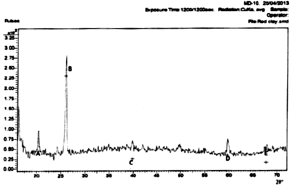
Figure 1. Mineralogical analysis of Sample A (red clay)
Hint: A- Kaolinite, B- Kaolinite, C- Kaolinite, D- Kaolinite, E- Quartz
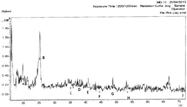
Figure 2. Mineralogical analysis of sample B (pink clay)
Hint: A- Quartz; B, C, J- Alumina; C-I- Kaolinite
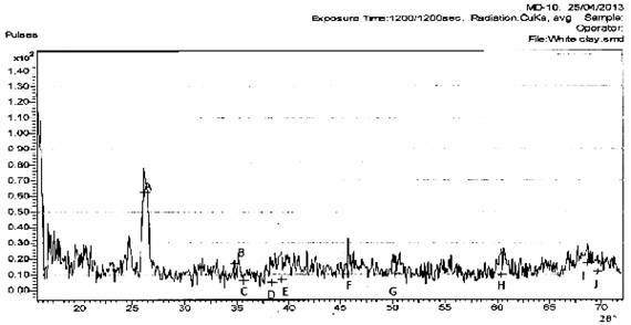
Figure 3. Mineralogical analysis of sample C (WHITE CLAY)
Hint: A- J- Kaolinite
Table 3 gives the plastic indices for the three clay samples A, B, and C indicating sample B with the lowest plastic index of 4.45% while samples A and C has 10.00% and 13.85% respectively.
Table 3. Plasticity indices
|
clay samples |
LL (%) |
PL (%) |
plastic index |
|
A (red) |
45.00 |
35.00 |
10.00 |
|
B (pink) |
58.00 |
53.55 |
4.45 |
|
C (white) |
41.00 |
27.25 |
13.85 |
Samples A and C fall within the range 10 - 60% recommended for ceramic clays as stated by [18, 20] which indicate they can both accommodate inert additives for molding [21]. Sample B is therefore non-plastic clay.
Table 4 gives the results of the physical tests carried out on the clay samples A, B, and C.
Table 4. Physical test of Abaji clay samples
|
Clay samples Tests |
A (red) |
B (pink) |
C (white) |
|
Apparent porosity (%) |
20.78 |
13.82 |
25.90 |
|
Shrinkage (% ) |
2.04 |
0.95 |
1.90 |
|
Bulk density (g/cm³) |
1.63 |
1.78 |
1.58 |
|
PLCR (%) |
2.08 |
2.08 |
2.08 |
|
Thermal shock (cycles) |
15 |
17 |
11 |
|
Refractoriness (PCE) |
1100 °C |
1100 °C |
1100 °C |
|
Loss on Ignition (%) |
0.17 |
0.22 |
0.39 |
The physical test results show that samples A, B, and C has an apparent porosity of 20.78, 13.82, and 25.90% respectively indicating that they all fall within the standard range for dense fire clay bricks (20-30%) and siliceous clay (23.7%) according to [19].
The bulk density 1.63, 1.78, and 1.58 g/cm3 for the three clay samples A, B, and C respectively also fall below the standard range of 1.98 g/cm3 for fire clay according to [17] and below the standard range of 2.0 g/cm3 for siliceous fireclay as stated by [19]. The permanent linear change on re-heating for the three clay samples A, B, and C fall far below the standard range of 4-10% as stated by [19] indicating that they cannot undergo excessive shrinkage during use under high temperature condition.
The thermal shock for the three clay samples however fall below the acceptable range of 20-30 cycles for fire clay but surpasses that of siliceous clay according to [19] indicating that the clays can only be used as lining in the furnace or lining of cable slag pots as stated by [6]. The three samples A, B, and C exhibited the same refractoriness of 1100 °C which fall far below the acceptable range of 1580 – 1750 °C for fire clay according to [15] and 1430 -1717 °C for both ceramic and refractory bricks as stated by [19]. And this may be attributed to the high amount of lime (CaO) as flux in the clay materials.
The implication therefore is that the clay materials (A, B, and C) cannot be suitable for high temperature furnaces or ovens but they can still find application as insulating bricks and for use in heat treatment furnace or ovens not more than 900-1000 °C.
Conclusions
The following conclusions can be drawn within the limit of this research:
¸ Abaji clay deposits meet the standard requirement to be used as refractory clay based on the results of this experimental work.
¸ Abaji clay can only be suitable for lining in the furnace or slag pots due to the lower thermal shock cycles; and for heat treatment ovens, test kilns that cannot be fired higher than 1100 °C.
References
1. Hassan S. B., Modern refractories: production, properties, testing and application, Zaria: Timo Commercial Printers, 2005.
2. Jock A. A., Ayeni F. A., Jongs L. S., Kangpe N. S., Development of refractory bricks from nigerian nafuta clay deposit, International Journal of Materials, Methods and Technologies, 2013, 1, p. 189-195.
3. Borode I. O., Onyemaob O., Omotoyinbo J. A., Suitability of some nigerian clays as refractory raw materials, Nigerian Journal of Engineering Management, 2000, 3, p. 14-18.
4. Adondua S., Indigenous refractory raw materials base for nigerian steel industry, Journal of the Nigerian Society of Chemical Eng, 1998, 7, p. 322-327.
5. Obadinma E.O., Development of refractory bricks for heat treatment facilities, J. of Sci. and Tech. Res., 2000, 2, p. 13-17.
6. Abubakar I., Birnin Yauri U. A., Faruq U. Z., Noma S. S., Sharif N., Characterization of dabagi clay deposit for its ceramics potential, African Journal of Environmental Science and Technol., 2014, 8, p. 455-459.
7. Atanda P., Adeniji O., Oluwole O., Development of heat treatment refractory brick using local nigerian clays, International Journal of Materials and Chemistry, 2012, 2, p. 185-191.
8. Omowumi O. J., Characterization of some nigerian clays as refractory materials for furnace lining, Nigerian Journal of Engineering Management, 2001, 2, p. 9-13.
9. Hassan S. B., Adewara J. O. T., Refractory properties of some nigerian clays, Nigerian Soc. Eng. Trans., 1993, 28, p. 21-25.
10. Matthew P., Investigation of the properties and processing of synthetic foundry sand mixture prepared from local material, B.Sc Thesis, ABU, Zaria, Nigeria, 1977.
11. Aniyi J. A., Adewara J. O. T., Refractory properties of kankara clay, Proc. Ann. Conf. Nigeria Metal. Soc., 1986.
12. Abolarin M. S., Olugboji O. A., Ugwuoke I. C., Experimental investigation on local refractory materials for furnace construction, Proc. 5th Ann. Eng. Conf., Federal University of Technology, Minna, Nigeria, 2004.
13. Folorunso D. O., Aramide F. O., Olubambi P., Borode J. O., Effects of firing temperatures on the performance of insulating firebricks containing different proportions of alumina and sawdust, JMMCE, 2015, 3, p. 309-317.
14. Lawal G., Amuda M. O. H., Adeosun S. O., The effects of cow dung and graphite on the properties of local refractory clay, NJERD, 2005, p. 1-8.
15. Misra M. I., Refractories: their manufacture, properties and use, 4th ed. Lakshmi, Krishna colony, Ghamapur, Jabalphur, 1975.
16. Norsker H., The self-reliant potter: refractories and kilns, Germany: Friedr. Vieweg & Sohn Verlagsgesellschaft mbH, 1987.
17. Chester J. H., Refractories, production and properties, The Iron and Steel Institute, London, 1973.
18. Grimshaw R. W., The chemistry and physics of clay and allied ceramic materials, 4th ed. Revised New York, Wiley Interscience, 1971.
19. Omowumi O. J., Characterization of some nigerian clays as refractory material for furnace lining, Nigerian Journal of Engineering Management, 2000, p. 1-4.
20. Nnuka E. E., Enejor C., Characterization of nahuta clay for industrial and commercial applications, NJEM, 2001, 2, p. 9-13.
21. Head K.H., Manual of soil laboratory testing: soil classification and compaction tests, ELE International Ltd., London, 1984.