Engineering,
Environment
Application of computer aided
design for palm kernel shell steam boiler
Kamoru Olufemi OLADOSU1,3*, Buliaminu KAREEM2,
Basil Olufemi AKINNULI2 and Tesleem Babatunde ASAFA1,3
1Department of
Mechanical Engineering, Ladoke Akintola University of Technology Ogbomoso, Oyo
State, Nigeria
2 Department of Mechanical
Engineering, Federal University of Technology Akure, Ondo State, Nigeria
3Science and Engineering Research
Group (SEARCH) LAUTECH, Oyo State, Nigeria
E-mails:
kooladosu@lautech.edu.ng, karbil2002@yahoo.com, ifembola@yahoo.com and
tbasfa@lautech.edu.ng
*Corresponding
Author: +234 803 595 9872
Received: December 21, 2016
/ Accepted: June 13, 2017 / Published: June 30, 2017
Abstract
Steam boiler is an integral and important component of
steam turbine used for electricity generation. Its design is however complex,
time consuming and prone to errors if done manually. This study aimed at using
computer based approach to design palm kernel shell combusting furnace for
generating a desired amount of electricity. By way of backward calculation
approach, standard design equations were used to size furnace and its
components. The equations were coded and solved using C-Sharp programming
language. The results showed that to generate 5 kW of electricity from palm
kernel shell; 5.5 kW turbine, 3.1 m super heater, 3.8 m riser, furnace of 1.432
m height and 0.45 m3 volume were required having considered power
loss due to friction and others. While these results are in good agreement with
those calculated manually, human errors are virtually eliminated. In addition, calculations and drafting time were reduced from 5 hrs. 47
minutes when done manually to about 4 minutes when the developed code was used.
This code can be used to size boiler for any desired power output.
Keywords
Steam boiler; Palm Kernel Shell; Design; Computer aided; Power
output
Introduction
In palm oil processing industry, biomass residues can be converted
from being potential environmental pollutants to useful fuel for steam and
electricity generation which are largely needed for industrial use [1]. Nigeria,
being the fifth largest producer of palm oil, accounts for about 1.5% (930,000
metric tonnes) of the global output. However, a huge quantity of oil palm
residues which could otherwise be used for energy generation are being wasted
[2]. In [3] is reported that about 30 tonnes of fresh fruit bunches /hr.
produce from a few palm oil mills can be used to generate up to 20 - 35 MW of
electricity. This can significantly reduce greenhouse gases and increase
employment for local population [1].
There are several technologies that enable oil palm mill to generate
enough energy for its consumption and sometimes for export. Among them are
fixed (1 kW- 50 MW), fluidized (5 MW- 100 MW) and dust technology (10 MW- 500
MW). Efficiencies of these technologies are dependent on fuel properties and
the mixing quality between flue gas and combustion air [4]. Pitchet and Vladmir
[5] recorded high combustion efficiency and low emission performance in a
fluidized bed combustion of palm kernel shell using optimized particle size,
although the start up and running cost of operation associated with this
technique make it difficult to be operated by small scale business. Remarkable
improvement has also been recorded on design of large scale grate furnaces
(fixed bed), yet additional work need to be done in small scale businesses in
term of poor mixing especially when co-firing different fuel and high moisture
fuel content for improve combustion and reduction of ash deposition on
components of grate furnace [6].
The unique features of grate furnace are the tolerance of fuel type;
positive movement of fuel down grates reduces blockages and well controlled air
distribution lead to high combustion efficiency [7]. In addition, the use of
additive mixed with solid wastes can significantly reduce alkaline metals
deposition on the surface of riser tubes [8] and [9]. These will increase
combustion process and decrease ash deposition. Boiler design is a complex and
time consuming procedure. It is also prone to errors if done manually. Previously,
emphasis was laid on primitive and probabilistic design processes which
resulted in high cost of production. Dimensions of boiler for power generation
often depend on fuel and vaporization efficiency; the mass balance, heat
balance and heat transfer which has to be specified through empirical results
and experiences. The aim of this study is to use computer based approach to
design palm kernel shell combusting furnace for generating a desired amount of electricity,
thereby providing substantial savings in terms of time and cost of production.
Nomenclature
A Area (m2)
H Height (m)
V Volume (m3)
m Mass (kg)
h Heat transfer coefficient
(kJ/kg)
k Thermal conductivity (W/m0C)
d Diameter (m)
L Specific latent heat of
vaporization (2256kJ/kg)
C Specific heat capacity (kJ/kgK)
q Heat duty required (J/s)
T Temperature (0C)
M Molecular mass of flue gas
(kg/kMol)
U Overall heat transfer coefficient
t Wall thickness
R Characteristic
gas constant (J/kg0C)
P Power
(W)
Ps Pressures
at steam drum (N/m2)
Cpm Specific
heat capacity of steam (kJ/mol0C)
mS Mass
flow rate of steam (kg/s)
c Size
of bottom PKS fired furnace (m)
Greek
symbols
 Generator efficiency
 Index number
 Dryness fraction of steam/water
mixture
Dryness fraction of steam/water
mixture
 Dynamic viscosity of the flue gas
(kg/ms)
Dynamic viscosity of the flue gas
(kg/ms)
α Exterior angle of truncated cone (Degree)
Material and method
Palm Kernel Shell (PKS) were collected from a local palm oil
processing mill in Ogbomoso, Southwestern Nigeria. The shells were crushed into
smaller pieces by using a granulator (SG-16 Series) and further reduced with a
blender. They were subsequently sieved to 5.0 mm particle size according to [5]. The proximate and ultimate analyses of the PKS
were done following [10]. Higher Heating Value (HHV) of the mixtures was
determined using GallenKamp Bomb Calorimeter according to [11].
Development of Grate Furnace and its Components
The furnace under consideration was based on principle
of water tube natural circulation. The main components of this furnace are
steam drum, down comer, riser tubes which represents the complete fluid flow
loop. Water flows to the steam drum through down comer riser loop.
The riser tubes were situated inside furnace where heat
of flue gases vaporizes the water into steam and back to the steam drum through
steam header collection (Fig. 1). Because steam water mixture inside riser
tubes is less dense than the saturated water at inlet tube, fluid flows upwards
in the riser tubes and back to the drum. The density difference between water
at the inlet tube and steam-water mixture produces enough force to overcome
friction and gravitational resistance to flow, therefore maintain a steam flow
system [12]. The steam drum is partitioned into two zones.
The lower section allows water intake to the drum while
the upper section produces steam which flows from the top of the drum into the
super heater tube. The superheated steam is expected to turn turbine to
generate electricity.
The design analysis follows backward calculation
approach of sizing the power plant component to generate steam for 5 kW of
electricity (Generator-Turbine-Super heater -Riser tubes- Furnace dimensions).
The design approach to each component is described in the following sections.
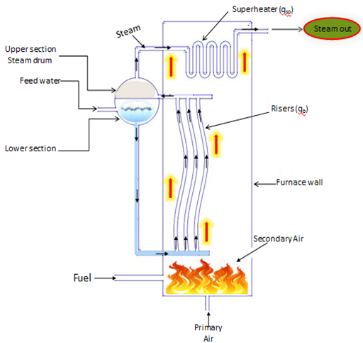
Figure 1. Schematic
diagram describing water to steam circulation loop
Turbine
Turbine is a rotary engine that converts the energy of the steam,
water or gas into mechanical energy. The mechanical energy is then transferred
through a driven shaft to power electric generator. The power input from
turbine  (kW) can be related to the
power output of generator
(kW) can be related to the
power output of generator (kW) by
Eq. (1).
(kW) by
Eq. (1).
 (1)
(1)
The generator efficiency ƞ is calculated from Eq. (2).
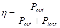 (2)
(2)
Where: 
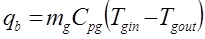
Mass flow rate of steam ms (kg/s) from super heater
entering turbine was estimated using energy equation for adiabatic expansion
which relates the power output to steam energy declining by passing through the
turbine [13], Eq. (3):
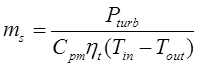 (3)
(3)
For steam,  [14]
[14]
But, , therefore:
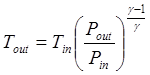 (4)
(4)
Where: Tin - inlet steam temperature (0C), Tout
- outlet steam temperature (0C), ϒ - index number, Cp
- specific heat capacity of steam at constant pressure (kJ/kgK) and Cv
- specific heat capacity of steam at constant volume, Cpm - mean specific heat capacity of steam (kJ/mol0C), ηt
- efficiency of steam turbine; For 5 kW power rating, Tin, Pin,
Pout, and ηt are 4000C, 0.1 MPa, 0.45
MPa, and 80% respectively. These were the state properties of superheated steam
obtained from [15].
Coulson and Richardson [16] defined the mean
specific heat capacity Cpm over the temperature range T1 to T2 as follow,
Eq. (5):
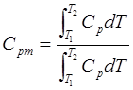 (5)
(5)
The specific heat capacity (Cp), as a function of temperature,
is given by Eq. (6):
 (6)
(6)
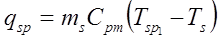
Super heater
Super heater is heat exchanger that
transfers heat energy from a heating medium to a heated medium. The heating
medium is usually flue gas while the heated medium is steam. The energy balance
equation of super heater is:
 (7)
(7)
Where: qsp - heat duty required by the super heater (J/s), Tsp1 (0C) and Ts (0C) are
the temperature of superheated and saturated steam from super heater and boiler
respectively.
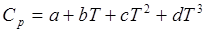
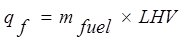
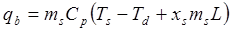
The energy balance equation of the riser
tube is given by Eq. (8):
 (8)
(8)
Assuming the water from down comer is
saturated  = 1000C,
and
= 1000C,
and  = 1000C; steam
is in equilibrium with water in the riser. = = 1000C, Therefore Eq. (9):
= 1000C; steam
is in equilibrium with water in the riser. = = 1000C, Therefore Eq. (9):
 (9)
(9)
Where: qb - heat duty required by riser tube (J/s), L - specific latent heat of vaporization  (2256 kJ/kg), xg - dryness
fraction of steam/water mixture.
(2256 kJ/kg), xg - dryness
fraction of steam/water mixture.
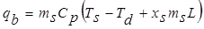
 (10)
Where: mfuel - mass of the fuel (kg/hr), qf - heat liberated by the
fuel (J/s).
(10)
Where: mfuel - mass of the fuel (kg/hr), qf - heat liberated by the
fuel (J/s).
 (11)
(11)
Furnace volume
Chungen [17] documented typical value of volumetric heat release
rate qv, for biomass as 0.176 MW/m3. Similarly, Sebastian (2002) reported furnace strain
level largely depends on different fuels and if the electric power of the plant
is known, strain levels for volume can be chosen. A large number of package
boilers have a cylindrical furnace with truncated cone as shown in Figure 2. The
exterior angle of the truncated cone is within 50 to 550C. The
furnace volume V (m3) grate area and furnace height h (m) can be
obtained from Eq. (12-14), respectively.
 (12)
(12)
 (13)
(13)
 (14)
(14)
Sizing of riser and super heater
The heat duty required in the riser is given by Eq. (15):
 (15)
(15)
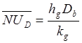
And the overall heat transfer (U) based on the outside area (A) of
the riser tube can be estimated as;
 (16)
(16)
Where: hg
- heat transfer coefficient of flue gas (kJ/kg), tr - wall thickness of riser tube  , kw
- thermal conductivities of stainless steel (304), (W/m0C), d0 (m) and di (m) are
internal and external pipe diameter, hb1 - heat transfer coefficient
of water boiling (W/m0C).
, kw
- thermal conductivities of stainless steel (304), (W/m0C), d0 (m) and di (m) are
internal and external pipe diameter, hb1 - heat transfer coefficient
of water boiling (W/m0C).
The analysis of heat transfer associated with flow past the exterior
surface of a solid is a complicated situation due to boundary layer separation
[21]. Nusset number can also be used to calculate heat transfer coefficient of
flue gas (hg).
Specific
heat capacity, dynamic viscosity and thermal conductivity of flue gas
Verbanck [18] determined specific heat
capacity of flue gas (Cpg) as the summation of the product of the
mass fraction of each component of flue gas mk (kg) by its
respective specific heat at the relevant temperatures ck (kJ/kg0C)
as:
 (17)
(17)
 (18)
(18)
Hassan and Ibrahim [19] stated that heat losses through casings must be accounted for if
accurate computation of flame temperature is to be made. This was done by
setting up heat balance equation for fuel gas as follows, Eq. (19-21):
 (19)
(19)
Where:
 (20)
(20)
According to [19],
 (21)
(21)
The dynamic viscosity μg (kg/ms) of flue gas is
obtained from Eq. (22) by [18]:  (22)
(22)
Thermal conductivity of the flue gas kg (W/m0C)
is determined from Eq. (23) by [20]:
 (23)
(23)
 (24)
(24)
From Eq. (23) and Eq. (24), we have;
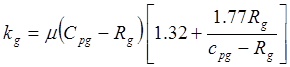 (25)
(25)
Where: Rg
- characteristic gas constant of flue gas; 


 ,
,
Cv - specific heat capacity at constant volume (kJ/kgK)
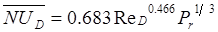
Prandtl and Reynolds numbers of the flue gas
The Prandtl number Pr and Reynolds number ReD of
flue gas are given by Eq. (26) and Eq. (27), respectively.
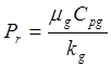 (26)
(26)
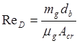 (27)
(27)
Where: Acr - cross sectional area of flow of flue gas; Db
- diameter of riser tube (m). For an external cross flow to a cylindrical pipe,
the Reynolds number range 40-4000 and Pr ≥ 0.7, the average
corresponding Nusselt number according to [21] is given by:
 (28)
(28)
 (29)
(29)
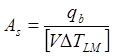
The empirical equation proposed by [22] for the calculation of heat
transfer coefficient of water boiling is as
follow:
is as
follow:
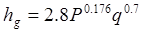 (30)
(30)
Valid at 0.2 bar ≤ P ≤ 98 bar.
Where: 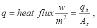 P: saturated pressure
(kPa), As - surface area of riser (m2)
P: saturated pressure
(kPa), As - surface area of riser (m2)
Evaluation of logarithmic mean temperature 
Heat obtained by the riser is the heat given out
by the flue gas
 (31)
(31)
For a cross flow heat exchanger, [23] gives the Logarithmic Mean
Temperature Difference as follow
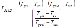 (32)
(32)
Where: Tgin – temperature of flue gas in (0C);
Tgout - temperature of flue gas out (0C); Tso –
temperature of saturated steam out (0C), Tsin –
temperature of saturated steam in (0C). From the equation (15) the total heat transfer surface area A (m2),
outside diameter d0 (m) and length of the tube; L (m) is given by;
 (33)
(33)
The following procedural steps / algorithm were adopted
to design the PKS combusting furnace using backward calculation approach.
- Calculate the turbine power input from turbine,
- Mass flow rate of system from super heater,
- Calculate heat duty required by the super heater,
- Calculate heat duty required by the riser tube,


c
|
|


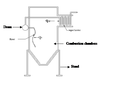
Figure 2. Schematic
picture of the furnace
- Calculate total heat duty required by the combustion chamber,
- Calculate heat liberated from the fuel,
- Determination of heat losses through wall furnace for an
accurate flame temperature. ,
.
- Calculate the volumetric flow rate,
- Determine the furnace volume, , area, and furnace height,
- Calculate the overall heat transfer U, based on the outside area
of the riser and super heater,
- Calculate Prandtl and Reynolds numbers of the flue gas.
, and 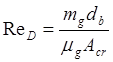
- Calculate the logarithmic mean temperature difference for a
cross flow heat exchange,
- Calculate the heat transfer area of the riser and to the heat duty
and overall heat transfer coefficient,
- Calculate the length of the risers and super heater required to
exchange the desire heat.

Software development
Based on the equations
(1-33) an algorithm was prepared and then translated to computer code using C#
programming language and .Net framework.
The flow chart upon which
the algorithm was based is shown in Figure 3.
The code receives input
parameters in order to size components for 5 kW of electricity and gives
dimensions of furnace, riser and super heater tube as outputs. In addition, 2D
drafting of combusting furnace was done in AutoCAD and was dynamically loaded
into the Visual Studio workspace of the application. It should be noted that
.Net frame work was selected because of its ease of deployment,
interoperability, automatic management of resources and cross platform support.
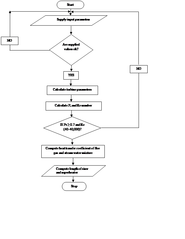
Figure 3. Flowchart
showing sizing of PKS combusting furnace
Here is the algorithm for the
software development:
(a)
Enter the electrical output power in kW and
efficiency of synchronous generator in (%) from design requirement;
(b)
The properties of the PKS based on its ultimate
analysis (i.e. carbon, hydrogen, oxygen nitrogen and sulphur) were supplied;
(c)
The mean fraction of the flue gas component mk and
the mean specific heat of the flue gas component ck available were stored in
the software database;
(d)
Submit to compute for turbine parameters;
(e)
Click on further calculations on furnace, heat
transfer coefficient of flue gas and heat transferred on super heater and riser
tube;
(f)
Submit to compute furnace parameters, convection
coefficient and length of super heater and riser tube; When all conditions
required for sizing furnace components have been adequately satisfied with
respect to the calculation to the six steps above, the design parameters are then
used to draft the 2D of the furnace. This is done through the drafting modules
wherein the geometries had been mathematically represented within the developed
software.
Fabrication and assembly of steam boiler
The components of the boiler developed are super heater, riser,
water tank, drum, and furnace chamber. Figure 4 and Table 1 showed the exploded
view of PKS combustion unit and their part list. Each of the component’s
fabrication process, material selection and cost analysis were not reported in
this paper.
|
|
Table 1. Part
list of PKS furnace
|
|
|
Item
|
Qty
|
Part list
|
|
1
|
1
|
Superheater exit port
|
|
2
|
3
|
Riser
|
|
3
|
1
|
Hopper
|
|
4
|
1
|
Primary air inlet
|
|
5
|
2
|
Ball bearings
|
|
6
|
1
|
Auger
|
|
7
|
1
|
Superheater
|
|
8
|
1
|
Furnace cover
|
|
9
|
1
|
Bricks
|
|
10
|
1
|
Furnace stand
|
|
11
|
1
|
Water tank stand
|
|
12
|
1
|
Water control valve
|
|
13
|
1
|
Water tank
|
|
14
|
1
|
Drum
|
|
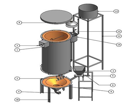
Figure 4. Exploded
view of PKS combusting furnace
Results and Discussion
Proximate and ultimate analysis
The proximate analysis of
the sample of PKS collected from a local oil palm mill in Iresapa Ogbomoso
Southwestern, Nigeria (Table 2) showed moisture content, volatile matter, fixed
carbon, and ash of 2.70%, 44.20%, 52.79% and 0.31%, respectively.
Table 2. Proximate
Analysis (% by weight on dry basis)
|
Property
|
This
study
|
[25]*
|
|
Moisture
|
2.70
|
5.40
|
|
Volatile matter
|
44.20
|
71.10
|
|
Fixed Carbon
|
52.79
|
18.80
|
|
Ash
|
0.31
|
4.70
|
Table
3. Ultimate Analysis (% by weight on dry basis)
|
Property
|
This study
|
[25]*
|
|
Carbon
|
45.12
|
48.06
|
|
Hydrogen
|
10.67
|
6.38
|
|
Nitrogen
|
0.27
|
1.27
|
|
Oxygen
|
40.11
|
34.10
|
|
Sulphur
|
0.62
|
0.09
|
|
LHV (MJ/kg)
|
17.12
|
16.30
|
These results are largely different from those of [25]. It can be seen that this
biomass contains low moisture and ash content which resulted to substantial
higher heating value of the shell while compared to [25]. Similarly, the
ultimate analysis (Table 3) shows that percentage weight of oxygen and hydrogen
content in this study are higher while carbon, sulphur and nitrogen content are
lower compared to those of [25]. This might be due to the variations in the
species, location, soil type, climatic condition of the palm kernel shell
sourced. The graphical user interface for sizing turbine parameters is shown in
Figure 5.
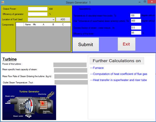
Figure 5. Template for the Turbine Parameters
The input parameters, which are the output power, efficiency of
generator and location of PKS used, are provided.
To obtain furnace parameters, length of riser and super heater tube,
‘further calculation’ bottom is clicked. For example, to size turbine
components for 5 kW of electricity generation, the efficiency of a synchronous
generator (90%) is provided and Ogbomoso is selected as the location of PKS
used.
Component dimensions based on the developed software
By clicking the ‘submit’ button, we obtained 5.56 kW of turbine,
0.0275 kg/s of steam entering turbine, 276.090C of outlet steam temperature and
0.03571 kJ/mol0C of mean specific capacity of the steam (Figure 6).
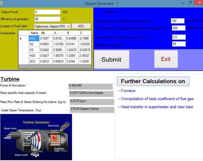
Figure 6. Output Screen for the Turbine Parameters
These values are required to generate 5 kW of electricity. By
clicking ‘further calculations on furnace’ heat transfer coefficient of flue
gas and heat transferred on super heater and riser tube, the furnace can be
appropriately sized.
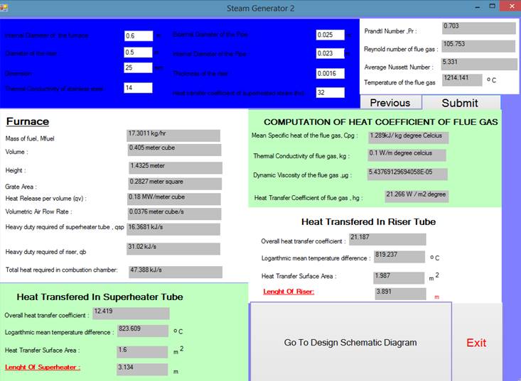
Figure
7. Output Screen for the Furnace parameters and Length
of riser and super heater tube
For 5 kW; 17.36 kg/hr of fuel, 0.405 m3 volume, 1.432 m height and
0.0376m3 volumetric air flow rate are needed (Figure 7).
The equivalent designed PKS combusting furnace is shown in Figure 8.
The software can be used to size furnace for generating specified power.
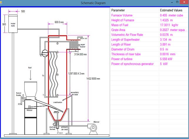
Figure
8. Output Screen Schematic Drawings and Estimated
Values of (5 kW) PKS Combustor
Table
4. Comparison of Parameters Based on Algorithms Generated and Traditional
Calculations
|
Parameters
|
Traditional
Calculations
|
Based
on Algorithm
Generated
|
|
Power of the
turbine (kW)
|
5.510
|
5.500
|
|
Mass flow rate
of steam entering turbine (kg/s)
|
0.028
|
0.028
|
|
Outlet steam
temperature (0C)
|
276.10
|
276.05
|
|
Mean specific
heat capacity of steam (kJ/mol0C)
|
0.0362
|
0.0357
|
|
Mass of fuel
(kg/hr)
|
17.300
|
17.301
|
|
Volume of
furnace (m3)
|
0.414
|
0.405
|
|
Grate Area (m2)
|
0.283
|
0.287
|
|
Height of
furnace (m)
|
1.4325
|
1.4325
|
|
Volumetric air
flow rate (m3/s)
|
0.035
|
0.035
|
|
Diameter of
drum (m)
|
0.500
|
0.500
|
|
Thickness of
riser tube (m)
|
1.6
|
1.6
|
|
Heat duty of
riser tube (kJ/s)
|
31.01
|
31.02
|
|
Heatduty
required of superheater tube (kJ/s)
|
16.461
|
16.368
|
|
Total heat
required in combustion chamber (kJ/s)
|
47.349
|
47.388
|
|
Length of
riser tube (m)
|
3.782
|
3.891
|
|
Length of
superheater (m)
|
3.135
|
3.135
|
To validate the accuracy of the developed
software, we compared the results obtained based on algorithms generated and
traditional calculations. The results are found to be very similar (Table 4). In
terms of time saving, traditional calculations and drafting of furnace
components details took about 5 hrs. 47 minutes while the same process was
completed in 4 minutes when the algorithm generated was used. In addition,
inaccuracies due to human errors are virtually eliminated.
Conclusion
Traditional calculations and drafting of
furnace components details took about 5 hrs. 47 minutes while the same process
was completed in 4 minutes when the software was used. For a fuel feed
rate of 17.3 kg/hr. and volumetric air flow rate of 0.035 m3/s; the
power of the turbine, volume of furnace, length of super heater, and risers
tubes required for 5 kW power rating were 5.5 kW, 0.405 m3, 3.89
m and 3.13 m respectively.
Reference
1.
Sulaiman N., Abdullah H., Gerhauser A. S., An
outlook of Malaysian energy, oil palm industry and its utilization of wasted as
useful resources, Biomass and Bioenergy, 2011, 35, p. 3775-3786.
2.
Izah S., Ohimain E., Angaye T., Potential
Thermal Energy from Palm Oil Processing Solid Wastes in Nigeria: Mills
Consumption and Surplus Quantification, British Journal of Renewable
Energy, 2016, 1, p. 39-45.
3.
Muhammad A., Tjahjono H., Meta R., Analysis
of Palm Biomass as Electricity from Palm Oil Mills in North Sumatera,
Energy Procedia, 2014, 47, p. 166–172.
4.
Sjaak V., Jaap K., Handbook of biomass combustion
and co-firing, 2008, ISBN-13:978-1849711043.
5.
Pichet N., Vladimir I., Combustion of palm
kernel shell in a fluidized bed : Optimization of biomass particle size
and operating conditions, Energy conversion and management, 2014, 54 (01),
p. 1–9.
6.
Najmi W. M., Rosil A. N., Izat M. S., Combustion
Characteristics of Palm Kernel Shells Using an Inclined Grate Combustor,
Journal of Faculty of Mechanical Engineering UiTM Malaysia, 2007, p. 15–28.
7.
Thomas R., Jabouille F., Torero J. L., Effect
of excess air on grate combustion of solid wastes and on gaseous products,
International Journal of Thermal Sciences, 2009, 48, p.165–173.
8.
Liang W., Lovås T., Houshfar E., Effect of
Sewage Sludge Addition on Potassium Release and Ash Transformation during Wheat
Straw Combustion. available from
http://www.aidic.it/cet.(Accessed 10 March, 2013) 2014,37, p. 7–12.
9.
Kamoru O. O., Buliaminu K., Basil O., and Abass
O. A., Optimization of Ash Yield from the Combustion of Palm Kernel Shell
and Selected Additives (Al2O3, CaO, MgO) Using D-Optimal
Design, Leonardo Electronic Journal of Practices and Tecchnologies, 2016,
28, p. 9-8.
- ASTM 3174-76 Standards method of proximate analysis of coal
and coke, in gaseous fuels; coal and coke section 5, Annual Book of
ASTM Standards, 2001, 5, p. 299.
- ASTM E711-87 Standards test method for gross
calorific value of coal and coke using GallenKamp bomb calorimeter, in
gaseous fuels; coal and coke, section 5, Annual Book of ASTM Standards
2001, 5, p. 25.
12. Astrom K., J. Bell R. D., Drum-boiler dynamic, Automatica
2000, 36 p. 363-378.
13. Chaibakhsh A., Ghaffari A Simulation Modelling Practice and
Theory Steam Turbine Model, Simulation Modelling Practice and Theory, 2008,
16 p.1145–1162.
- Kyle B.G., Chemical and Process Thermodynamic 3IE Adapted by
Permission of Pearson Education, Inc., Upper Saddle River,
www.cen84959_ch18_ap01.qxd (Accessed 15 April, 2013), 2000.
15. Steam Turbine V-FLO Pumps and System available from www.VfLO.Com
(Accessed 18 June, 2013), p. 5-8.
16. Coulson R., Chemical Engineering Design fourth edition,
2005, 6, p. 634-693.
17. Chungen Y., Rosen-dahl L., Kær S. K., Grate-firing of biomass for
heat and power production, Progress in Energy and Combustion Science, 2008,
34, p. 725–754.
18. Verbanck, Development of a mathematical model for water tube
boiler heat transfer calculations, Proc S Afr Sug
Technol Ass, 1997 p. 166-167.
19. Hassan A., Ibrahim A., Calculation of Radiant Section
Temperatures in Fired Process Heaters, Scientific Research to Knowledge,
2013,(5)1 p. 1–6.
20. Eucken M., A model maxwell-Eucken equation for calculating the
thermal conductivity of two component solutions or mixtures, Journal of
Refrigeration, 2005, 4, p. 223-225.
21. Illinois Institute of Technology (IIT), Convection Workshop
Academic Resource Centre, Available from http:// www.iit.edu.(Accessed 10
January, 2014), 2013.
22. Kandlikar, Penniger K., A General Correlation for Saturated Two-Phase
Flow Boiling Heat Transfer Inside Horizontal and Vertical Tubes, Heat
Transfer, 2006,112, p. 219–228.
23. Sebastian T., Thermal Design of Heat Exchangers, Energy
Engineering and Environmental Protection, 2002, p. 4–9.
24. Rajkumar T., Ramaa V. M., Gobi K., Boiler drum level control by
using wide open control with three element control system, Journal of Research
in Management and Technology, 2013, 11, p. 85-96.
25. Ninduangdee P., and Kupranov V. I., Fludised-Bed Combustion of Biomass with
Elevated Alkali Content: A Comparative Study between Two Alternative Bed
Materials, International Journal of Chemical, Nuclear, Metallurgical and Materials
Engineering, 2014, 8, p. 267-274.