Engineering, Environment
Sizing modelling and simulation of PV generation system feeding a 6 MW induction motor dedicated to pumping applications
Mohammed Omar BENAISSA*, Samir HADJERI, Sid Ahmed ZIDI
Intelligent Control and Electrical Power System Laboratory, Djillali Liabes University
Sidi Bel-Abbes, Algeria
E-mail(s): *omarioriquelme10@yahoo.fr; shadjeri2@yahoo.fr; sbzidi@yahoo.fr
* Corresponding author: Mohammed Omar BENAISSA, phone: +213558481869
Received: February 20, 2017 / Accepted: June 14, 2017/ Published: June 30, 2017
Abstract
This paper proposes an autonomous photovoltaic (PV) pumping system for rural/remote applications especially in the large desert in northern Africa where the sun radiation is abundant. Since PV generators exhibit nonlinear I-V characteristics and their maximum power point varies with solar radiation. For this reason, the MPPT controller is used to optimize the solar energy conversion by guaranteeing fast maximum power point tracking (MPPT). This feature has an essential role in dynamic response and efficiency of the photovoltaic system, thus it maximizes the amount of extracted natural gas to be conveyed to another site for an ulterior utilization. Here a robust maximum power point tracker (MPPT) using incremental conductance algorithm is applied to the duty cycle value of the DC-DC converter which acts directly on the drive speed. A DC/DC boost is used to enhance voltage up to the favourite level and the SVPWM inverter connects it to a powerful induction motor for a pumping of natural gas application, these systems are at the heart of many industrial sectors such as the oil industry, the production of thermal and nuclear energy etc. An understanding of how these systems operate is essential to increase their performance and reduce their operating costs. Furthermore, three phase voltage-fed PWM inverters are recently showing growing popularity for multi-megawatt industrial drive applications, the main purpose of these topologies is to provide a three-phase voltage source, where the amplitude, phase, and frequency of the voltages should always be controllable. The model of a three-phase voltage source inverter is modelled and discussed based on space vector modulation theory. Simulation results are obtained using MATLAB/Simulink environment for effectiveness of the proposed system.
Keywords
Natural gas pumping system; Maximum power point tracking (MPPT); Incremental conductance; DC/DC boost converter; Space vector modulation (SVM); 6MW induction motor; Centrifugal compressor
Introduction
The principal source of electrical energy is the hydrocarbon based fossil fuel. CO2 emission from fossil fuel based on power plants is a major cause of global warming. In addition, the availability of such energy resources is very limited for the future consumption [1]. These are the reasons, which attract many researchers to work in the area of renewable energy. Among all the available renewable energy sources, solar photovoltaic (PV) system has several advantages such as clean energy and potential to provide sustainable electricity to remote areas [1,2]. The geographical location of Algeria promotes the development and growth of using the solar energy. In fact, given the importance of the intensity of the radiation received and the duration of sunshine that exceeds ten hours a day for several months, our country can cover some of the needs in solar energy, these advantages could be beneficial in the isolated regions especially in applications of photovoltaic pumping [4]. The use of PV as an energy source for pumping is considered one of the most promising fields of solar energy [6]. The pumping system with direct coupling is simple, reliable and cheaper because it does not include voltage regulators. Its advantages contributed to its widespread use throughout the world. PV generator does not require either the current value or the operating voltage, it’s the load which determines the operating point. In steady state, the operating point of the system is obtained by the intersection of the characteristics Ipv -Vpv of the PV generator and the motor-compressor group [7]. The induction motor became standard for solar pumping applications mainly due to its simplicity, robustness and low cost compared to the DC motor [6]. This paper presents the sizing and modelling of a PV generation system connected to a motor-compressor group by a boost converter and DC/AC inverter using SVPWM control. The advantages offered by the three-phase VSI controlled by SVPWM over the classical SPWM are well documented in [17,19]. The original inspiration of this work is obtained during a practical internship within a gas treatment unit located in the Southern of Algeria (Sahara), where we have noticed that the use of the turbine (TG-7) limits the process of gas transfer and thus it has major disadvantages due to its slow speed, also the number of stop time for curative and preventive maintenance work which can lead to a loss of production of about 77 672 00 m3/year of gas. Hence in order to reduce the stopping time and improve the availability of the unit, a revamping has been proposed by the replacement of the turbine (TG-7) by an induction motor powered by a PV generator. The authors have made an effort to model every component of the proposed system using Matlab/Simpower systems toolbox. Simulation results under a various solar radiation levels and constant temperature show an acceptable dynamic performance of the system.
Material and method
Solar potential in Algeria
Because of its geography and climate, Algeria has one of the highest solar resources in the world. The sunshine duration within almost all its national territory exceeds 2000 hours annually and can reach 3900 hours (Highlands and Sahara). The daily received energy on a horizontal surface of 1m² is approximately 5 kWh over most of the country, which is nearly 1700 kWh/m²/year in the north of the country and 2263 kWh/m2/year in the south. In the Sahara, this potential can be an important factor in sustainable development if it is exploited in an economical way. The following table shows the rate of the insolation for each region in Algeria [3-5].
Table 1. Solar potential in Algeria
|
Regions |
Coastal Regions |
Highlands |
Sahara |
|
Surface |
4% |
10% |
86% |
|
The average period of radiation (hours/year) |
2650 |
3000 |
3500 |
|
The average received energy (kWh/m²/year) |
1700 |
1900 |
2650 |
System description
The system consists of a PV array source constituted of 24241 solar modules of Suntech STP270S-24_vb type operate under a different radiation level ranging from 1000 to 250W/m² and a fixed temperature of 250C. The natural gas is pumped only over sunshine periods, for this reason such system can be called (along the sun pumping). A boost chopper follows the PV array in order to convert its varying MPP voltage into a fixed voltage feeding a three- phase two level voltage source inverter (VSI) controlled by SVPWM used to convert PV voltage input to variable sinusoidal voltage variable frequency signal as shown in Figure 1.
![]()
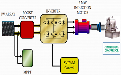
Figure 1. Schematic diagram of the proposed PV pumping system
The inverter is controlled by SVPWM switching logic to feed a three-phase 6MW induction motor driven a centrifugal compressor with parameters given in Appendix.
Sizing the components of photovoltaic pumping system
Estimating the power required by the mechanical load (IM-COMP)
According to the Maximum power of the compressor and in order to get a pumped natural gas for a given radiation and temperature, we can size the PV generator by choosing the best combination between the type and the number of the modules. First of all we start by estimating the required power of the load (motor-comp group), then we will be able to size the PV generator. According to the manufacturer catalog given in the Appendix, the maximum power required by the centrifugal compressor PMAX,comp = 5320 kW therefore the associated IM power (PMOT) will be corrected and calculated by the following equation (1):
PMOT > PMAX,comp · K · Kf (1)
Where K is the correction coefficient of the altitude and temperature equals to 0.9 if we consider the operating temperature of 55°C (according to the graph given in the appendix). Kf is the correction coefficient of 50 Hz frequency hence it equals to 1.
Consequently, the IM power is PMOT > 5912 kW, therefore the normalized power of the induction motor is PMOT = 6000 kW.
Sizing the PV Generator
The power supplied by the PV generator will be determined from the nominal power required by motor-compressor group. Furthermore, the use of DC/DC converter controlled by any MPPT algorithm in comparison to a direct connection should offer a quantifiable economic and energetic gain. It’s important to specify that there are no international standard states how the MPPT performances are measured. Also, the inverter efficiency is given between the energy consumed by the load and the energy delivered by the DC source [8].
Hence the following assumption will be considered Eq. (2):
ηTOT = ηCONV · ηMPPT · ηINV = 95% (2)
Where: ηTOT is the total efficiency of the conversion chain, ηCONV is the efficiency of the boost converter, ηMPPT is the efficiency of the MPPT controller, ηINV is the efficiency of the DC/AC inverter, ηMOT is the efficiency of the induction motor.
Consequently, Eq. (3):
PPVG.MAX = PMOT/( ηTOT · ηMOT) (3)
Hence the maximum power supplied by the PVG is: PPVG.MAX = 6000/(0.95·0.965) = 6545000
Also we have Eq. (4):
PPVG.MAX = NTOT · PModule.PV (4)
Where: PModule,PV is the maximum power supplied by one module of Suntech STP270S-24_vb type. NTOT is number of the total modules used in this work where NTOT=NS · NP, NS and NP represent the number of modules respectively in series and parallel.
Hence: NTOT = PPVG.MAX/PModule,PV = 6545000/270 = 24241
An inverter is characterized by a maximum allowable input voltage UMAX. The voltage delivered by the PV generator therefore should never exceed UMAX. The maximum number of PV modules in series is calculated by the following formula, Eq. (5):
NS = UMAX/1.15Vco = 5500/(1.15 · 44.4999) = 108; NP = NTOT/ NS = 225 (5)
The characteristics I-V and P-V of Suntech STP270S-24_vb module are represented in Figure 2.
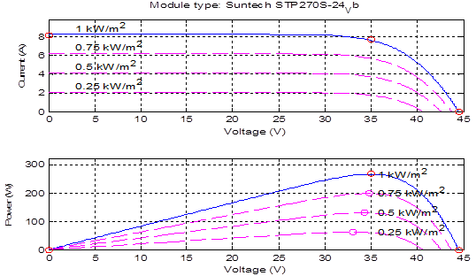
Figure 2. I-V and P-V characteristics of one module at 250C and varying irradiance
Table 2. Specifications of Suntech STP270S-24_vb PV module
|
Model name |
Suntech STP270S-24_vb |
|
No. of cells per module |
72 |
|
Open circuit voltage (VOC) |
44.4999 V |
|
Short circuit current (ISC) |
8.19978 A |
|
Maximum Power Voltage (Vmp) |
35V |
|
Maximum Power Current (Imp) |
7.70979 A |
The characteristics of PV array constituted of 108 series modules and 225 parallel strings are shown in Figure 3.
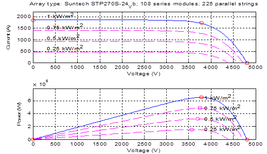
Figure 3. Array type: Suntech STP270S-24_vb, 108 series modules, 225 parallel strings
System component modelling
Boost Converter
Boost Converter is a DC-DC converter for which output voltage is greater than input voltage and it is necessary to regulate and provide suitable voltage to VSI (Figure 4).

Figure 4. Boost converter
In fact high gain DC-DC converters are often used as an important part of renewable energy conversion systems [9].
Many studies state that the operation of the boost converter is governed by the following equations (5-7):
![]() (5)
(5)
![]() (6)
(6)
TSW = TON+TOFF (7)
Where: VS is the source voltage, V0 is the output voltage of the converter, D is the duty cycle, FSW = 1/TSW is the switching frequency of the converter, TON On time period of the semiconductor switch, and TOFF is off time period of the semiconductor switch.
In this work the incremental conductance MPPT controller is implemented into the boost converter, this is to vary automatically the duty cycle in order to generate the voltage required to extract the maximum power.
Incremental Conductance Algorithm
The Incremental Conductance method offers good performance under rapidly changing atmospheric conditions. The derivative of output power P with respective to panel voltage VPV is equal to zero at Maximum Power Point (MPP). The slope of the PV array power curve is zero at the MPP, increasing on the left of the MPP, and decreasing on the right-hand side of the MPP. The basic equations 8-10, of this method, are as follows [15,16].
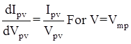 (8)
(8)
 (9)
(9)
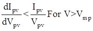 (10)
(10)
The flowchart of the incremental conductance method is fully documented in the literature such as in [15].
SVPWM Controlled Voltage Source Inverter
In this study, we will use the space vector PWM (SVPWM) because it allows feeding the induction motor with a greater voltage and less harmonics distortion [12].
The equivalent two-level SVPWM description for any level SVPWM is shown in Figure 5 [10]. Six switching space vectors are evenly distributed at 60° intervals with the length of 2Vdc/3 and form a hexagon. Also two zero space vectors are located at the center of a hexagon in the complex plane [20].
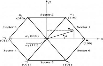
Figure 5. Sector implementation [19]
The projection of basic voltage vector and reference vector in the plane of a-b is shown in Figure 5. We can get voltage vector and the operating time of vector by using the following equations [14]:
|
|
(11) |
|
|
(12) |
|
|
(13) |
|
|
(14) |
|
|
(15) |
|
|
(16) |
Where: TS is the switching period, Vdc is the inverter input voltage and M is the modulation index. T1, T2, T0, T7, are respectively the operating time of V1, V2, V0, V7, in sampling period.
The Motor-Pump Group
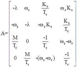
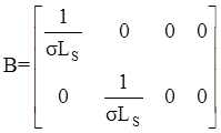
One of the most commonly models used for IMs is the d-q model [22], presented by Park. The mathematical dynamic model of the asynchronous motor is described in [13,18], by the following equation:
|
x′(t) = Ax(t) + Bu(t)x′(t) |
(17) |
|
With: xt = (IdsIqsφdrφqr)t |
(18) |
 ;
;  ;
;
![]()
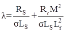
Where: Ids, Iqs, φdr, φqr are d-axis stator current, rotor flux and q-axis stator current, rotor flux respectively, Ls, Lr, Rs, Rr and M are stator and rotor main inductances, resistances and mutual inductance respectively.
ωs and ωr are the angular speed of the rotating magnetic and electric fields respectively, σ dispersion factor, d,q axes corresponding to the asynchronous reference axes in Park model.
The induction motor develops an electromagnetic torque Tem expressed as follows:
![]() (19)
(19)
Where: p is the number of pole pairs; The centrifugal pump torque Tr is assumed to be proportional to the square of the rotor speed [21]. The flow rate (Q) is directly proportional to the impeller speed [11]. So, the equations of centrifugal pump can be written in the following form shown below, Eq. (20):
Tr = KΩ² (20)
Where: K is the centrifugal pump constant.
Results and Discussion
In order to test the proposed pumping system efficiency, simulations using Matlab software have been performed (see Figure 6). Incremental Conductance method for harvesting the maximum power of the PV solar farm is used which provides good yields. As the insulation level varies during the day, the output of the PV array follows the change. The frequency of the inverter is intentionally left constant so that the change in speed of the induction motor is due only to the insulation level and the adopted MPPT method, so only we can appreciate its improvements.
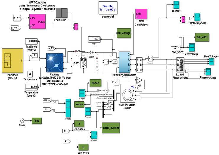
Figure 6. Overall SIMULINK Model
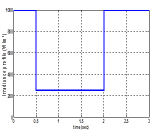
The performance of the proposed system has been tested with a step change in the solar insolation level. Thus, the solar insolation level assumed to vary abruptly between 1000 W/m² and 250 W/m² as shown in Figure 7.
The figures show the behaviour of the proposed pumping system by considering radiation variations.
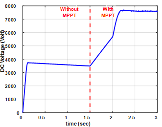
From t=0 to t=1.5 s the considered system is working without the MPPT controller, it is observed during this time interval that the machine is far from operating at its nominal conditions, thus we can say that the machine is not fully exploited. At t= 0.5 the performance of the pumping system is analysed by changing the radiation from 1000W/m² to 250W/m², consequently the current absorbed by the load has reduced considerably, however the change in the output voltage of the boost converter is very less (see Figure 8), and hence the rotor speed is reduced slightly (see Figure 10).
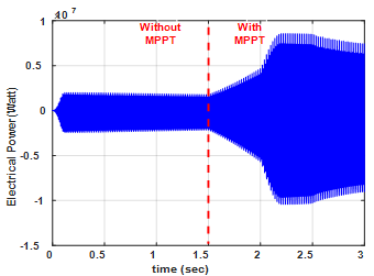
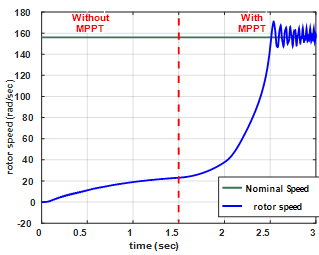
At t=1.5 s the MPPT controller is enabled with the help of the grey block (see Figure 6), it starts immediately acting on the duty cycle of the boost converter, the fact that will contribute to enhance the output voltage of the boost converter (see Figure 8), which allows to increase significantly the rotor speed (see Figure 10). So, in this way the tracking of the MPP can be ensured (see Figure 9).
At t=2 s the radiation level step up from 250 to 1000W/m², the MPPT controller continue tracking the MPP normally which demonstrates that radiation step changes do not pose a challenge to the incremental conductance algorithm, moreover with 1000W/m² radiation level, the control is becoming more attractive since the rotor speed has increased exponentially (see Figure 10).
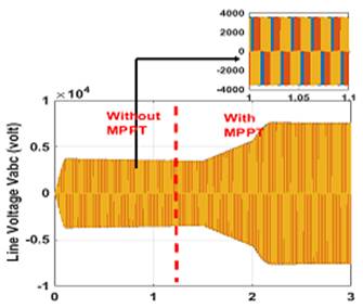
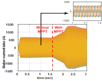
By the end of this period we can notice that the electrical power delivered by the PV array can exceed 6MW (see Figure 9) which allows the motor to operate around its nominal speed 156 rad/sec (see Figure 10), at this time the line voltage applied to the stator winding is 7700/√2 ≈ 5500 V (see Figure 11), and the current absorbed by the motor equals to 1050/√2 ≈ 750 A (see Figure 12). In fact the amount of efficiency increasing is coming from the difference of motor power with and without MPPT controller.
|
Figure 7. Irradiance profile (W/m²) |
Figure 8. Output Voltage of the Boost Converter (Volt) |
|
Figure 9. Electrical Power absorbed by the motor-pump group (Watt) |
Figure 10. Rotor speed (rad/sec) |
|
Figure 11. The output Line Voltage of the inverter (Volt) |
Figure 12. Current absorbed by the load (A) |
By using the Matlab’s powergui it can be seen that the THD of the stator current waveform is only 0.91% (see Figure 13).
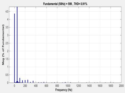
Figure 13. Harmonic Spectrum of stator current along with THD
Therefore, we can say that the SVPWM control has good performance given that it generates poor harmonic distortion of stator current.
Conclusions
From the analysis presented above the following conclusions can be derived:
- The considered pumping system can overcome the problem caused by the turbine (TG-7), and avoid interventions of preventive maintenance also reduce operating costs;
- The incremental conductance MPPT controller can drastically increase the efficiency of energy production compared to the system without MPPT;
- The MPPT shows good speed responses;
- SVPWM control is very suitable for high power load applications.
The results show clearly that the MPPT used can improve the effectiveness of the pumping system even for multi-megawatt industrial drive applications, therefore the system has been found to be satisfactory.
Appendix
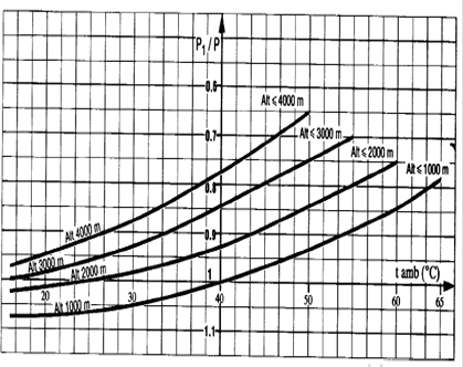
Figure 15. The Correction coefficient of the attitude and temperature
Table 3. Induction motor parameters
|
The Induction Motor Type (TPCB 900Z4) Class F, the Manufacturer SCHNEIDER |
|
|
PMOT |
6MW |
|
Nominal voltage |
5.5KV |
|
Nominal current |
725A |
|
Frequency |
50Hz |
|
rated speed |
1489 rpm |
|
Synchronous Speed |
1500 rpm |
|
Over speed |
1800 rpm |
|
Stator inductance (Rotor inductance) |
0.0075H |
|
Stator resistance |
0.02 Ω |
|
Rotor resistance |
0.025Ω |
|
Number of pairs of poles |
2 |
|
M |
0.0057H |
|
Inertia constant |
361Kg.m² |
|
Friction factor |
0.64 N.m.s |
|
Efficiency |
96.5% |
Table 4. Centrifugal compressor parameters
|
Centrifugal Compressor MARC THERMODYNE RC5S |
|
|
- |
4 bars: up to 16.9 |
|
Temperature |
500C to 157 |
|
- |
5 stages |
|
Rated Speed |
9664 rpm |
|
Rated power |
4409 KW |
|
Nominal Torque |
4227 N.m |
|
Start Torque |
10990 N.m |
|
Maximum Torque |
422270 N.m |
|
PMax, Comp |
5320 KW |
References
1. Blaabjerg F., Teodorescu R., Liserre M., Timbus A.V., Overview of control and grid synchronization for distributed power generation systems, IEEE Trans. Ind. Electron, 2006, p. 1398-1409.
2. Aurobinda P., Pathak M.K., Srivastava S.P., A single phase photovoltaic inverter control for grid connected system, 2016, (1), p. 15-30.
3. http: //www.sonelgaz.dz
4. Ministère de l’Énergie et des Mines, Guide des Énergies Renouvelables, Édition 2007.
5. Brahimi (MEM), Situation des énergies renouvelables en Algérie. In Conférence sur la maîtrise de l’énergie et de l’environnement dans un contexte d’économie de marche, 2001.
6. Chergui M.I., Benaissa M.O., Strategy photovoltaic pumping system in scattered area, In IEEE 4th International Conference on Renewable Energy Research and Applications, 22-25 Nov 2015, Italy.
7. Zarour L., Chenni R., Improvement of synchronous and asynchronous motor drive systems supplied by photovoltaic arrays with frequency control, Journal of Electrical Engineering, 2008, 59 (4), p. 169-177.
8. Angel M., Cid P., Conception et Réalisation de Modules Photovoltaïques Electroniques, Institut National des Sciences Appliquées de Toulouse, 2006.
9. Fathabadi H., Novel efficiency DC/DC Boost converter for using in photovoltaic systems, Solar energy, 2016, 125, p. 22-31.
10. Venkatesan M., Rajeswari R., Devaragan N.D., Implementation of a modified SVPWM-based three-phase inverter with reduced switches using a single DC source for a grid-connected PV system, Turkish Journal of Electrical Engineering and Computer Sciences, 2016, 24, p. 3023-3035.
11. Mrityunjaya K., Uday Kumar R.Y., Sheelavant V.R., Solar photovoltaic water pumping harnessing maximum power, ACEEE International Journal on Electrical and power Engineering, 2013, 4 (1).
12. BAGHLI L., Modélisation et commande de la machine asynchrone, IUFM de Lorraine–UHP, 2005.
13. Arrouf M., Bouguechal N., Vector control of an induction motor fed by a photovoltaic generator, Journal of Applied Energy, 2003, p. 159–167.
14. Shijie Y., Qun Z., Heng Du., A simplified SVPWM control Strategy for PV inverter, In: 24th Chinese Control and Decision Conference, p. 225-229.
15. Khlifi M.A., Study and control of photovoltaic water pumping system, Journal of Electrical Engineering Technology, 2015, p. 709-718.
16. Enany M.A., Farahat M.A., Nasr A., Modelling and evaluation of main maximum power point tracking algorithms for photovoltaics systems. Renewable and Sustainable Energy Reviews, 2016, p. 1578–1586.
17. Bo L., Chen W., Comparative analysis on PMSM control system based on SPWM and SVPWM, In: IEEE 28th Chinese Control and Decision Conference (CCDC), 28-30 May 2016, China.
18. Yaichi M., Fellah M.K., Mammeri A., A neural network based MPPT technique controller for photovoltaic pumping system, International Journal of Power Electronics and Drive System, 2014, 4 (2), p. 241-255.
19. Bin Ibrahim Z. et al., Simulation investigation of SPWM, THIPWM and SVPWM techniques for three phase voltage source inverter, International Journal of Power Electronics and Drive System, 2014, 4 (2), p. 223-232.
20. Hyun Jang D., Yong Yoon D., Space vector PWM technique for two phase inverters fed two phase induction motors, IEEE Transactions on Industry Applications, 2003, 39 (2), p. 543-549.
21. Zebiri F., Kessal A., Rahmani L., Chebabhi A., Analysis and design of photovoltaic pumping system based on nonlinear speed controller, Journal of Power technologies, 2016, 96 (1), p. 40-48.
22. Jannati M., Monadi A., Rumzi N., Idris N., Faudzi M., Athif A., Blaabjerg F., Modeling and rotor field-oriented control of a faulty three-phase induction motor based on GSA for tuning of PI controllers, Turkish Journal of Electrical Engineering and Computer Sciences, 2016, 24, p. 2084-2105.