Engineering, Environment
Thermal stresses of aluminium alloy under different pouring temperatures and thickness
Saliu Ojo SEIDU *, Solomon Oshioke AGBEDOR, John Damilola SUNDAY
Metallurgical and Materials Engineering Department, Federal University of Technology, Akure, Nigeria
E-mails: soseidu@futa.edu.ng; Soloatom1234@gmail.com; ajiroghenejohn@gmail.com
*Corresponding Author, phone: +234 8137724379
Received: November 29, 2017 / Accepted: April 08, 2018 / Published: June 30, 2018
Abstract
The effect of pouring temperature and thickness on the thermal stresses of aluminium alloy (AL6063) casting was investigated. Ten samples of three parallel round bars with centre bar largest, crossed with two perpendicular rectangular bars were produced in all with sand casting. Five of the castings were produced at different pouring temperatures with constant thickness of the 'centre bar' (40 mm). Others were produced at constant pouring temperature (7200C) with varied thickness of the 'centre bar'. The Pouring temperature range, for the investigation is 6800C to 8500C, while the diameter of the centre bar for varied thickness range from 20 mm to 60 mm at 7200C. The results showed that, lower pouring temperature (7200C) nearer to the melting temperature (6600C) of the alloy produced quality castings with minimal thermal stress value of 18.8475 Mpa. In the varied thickness, the thermal stress range is 12.7673 - 31.3854 Mpa. It was found that thermal stress of any casting thickness can be controlled at minimal range when the alloy is poured at temperature little above the melting point. Also, thermal stresses increases in castings as pouring temperature increases. The model was generated from curve fitting method for predicting magnitude of thermal tensile stresses in joint walls of aluminium alloys.
Keywords
Aluminium Alloy; Thermal Stresses; Tensile Stress; Compressive Stress; Pouring Temperature; Thickness; Castigliano Theorem; Sand Casting
Introduction
In the past, the foundry man has strived for ways to improve the quality of his cast and eliminate the defects that occurred in the casting by trial and error and past experiences. The time needed to produce a particular product is always wasted. Problems occurred in the cast were only solved through trial and error technique. Today advancement in technology and applications of scientific principles in engineering manufacturing has helped to eliminate such challenge. Metal casting is a versatile manufacturing process in which molten metal is poured into previously prepared mould cavity and allowed to solidify. Subsequently the product is taken out of the mould cavity, trimmed and cleaned to shape. Casting can produce products from few grams to several hundred tons and from simple shapes like watch cases to complex parts like engine blocks. It is a near net shape manufacturing process involving less or no further operations. Almost any metal or alloy which can be easily melted is castable [1].
The knowledge and understanding of casting parameters in casting different metals and alloys is as significant as the cast products to manufacturing engineers [2]. Casting has many process variations depending upon material, pattern, mould and the pouring technique. Sand casting is used to produce intricate parts in almost every melt that can be melted. For successful production of quality cast, one needs knowledge in the following operations: melting, pouring, and solidification process.
Solidification is a phase transition in which molten metal or alloys turn into solids when its temperature is lower below its melting point. The pouring temperature is the initial temperature of the melt, used for the casting as it is poured into the mould. Pouring temperature determines the temperature distribution, fluidity and built-up of pressure and thermal stresses in the casting. It has been stated [3] that, hot tearing may be best avoided by pouring at moderate temperature. The knowledge of melting temperature of metals and alloys is necessary to estimate their corresponding pouring temperature [4]. Aluminium alloy casting has melting temperature of 6600C [4]. It was also stated in [4] that this melting temperature may be as low as 6490C. The temperature gradient within the casting induced thermal stresses in the alloy. It is also known that the appearance of these stresses in joint walls with different thickness in solidifying casting is due to non-uniform cooling of parts [6]. Thermal stresses are those stresses existing within a casting in the absence of application of service or external stress.
The effect of pouring temperature on thermal stresses in AL6063 was investigated using Cutting-Edge Technique (CET), followed by the measurement of the change in the distance between prescribed markings on the centre bar to obtained change in length (Δl). This was used in computing Castigliano model to quantitatively determine the cumulative thermal stresses in the three round bars. It has been stated in [5], that when pouring temperature is lower than optimum, the mould cavity will not be filled completely or risers will solidify too rapidly and intercept directional solidification. On the other hand, higher pouring temperature causes shrinkage of the casting and mould warping [3]. Above all, many casting defects result because the optimum casting conditions were not used during the casting process.
The research aim is to determine the optimum points at which this parameter (pouring temperature) produce quality cast with minimal thermal stresses.
Materials and Method
Melting and casting
Aluminium billet was sized, carefully packed into a 10 kg capacity crucible and charged into a gas-fired pit furnace of 20 kg capacity for melting. Charge calculations were utilized to evaluate the quantities of melt and sufficiently superheated to 150C above the specified pouring temperature.
This allows for temperature drops encountered during reloading and temperature loss during the time required for pouring of the castings to be compensated for. The molten metal was deslaged and lift out with tong then ready to cast into prepared sand moulds.
The pouring temperatures of the aluminium alloy castings were measured with thermocouple. The probe of the thermocouple was allowed to make contact with the base of the molten metal contained inside the crucible. The corresponding temperature values in degree Celsius (0C) were obtained accordingly. The pouring temperatures are: 6800C, 7200C, 7500C, 8000C, and 8500C respectively.
Sample for CET
In this research work, the efforts made in ‘sand casting’ Aluminium alloy of ten samples of three parallel round bars with centre bar largest, crossed with two perpendicular rectangular bars is presented. For the first investigation of casting parameters (pouring temperature), five of this samples with constant centre round bar (40 mm) in Figure 1 were cast with five different pouring temperatures (680,720, 750, 800, and 8500C).
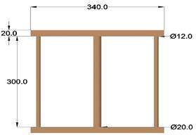
Figure 1. Pattern for sample
In the same vein, for the second investigation of casting parameters (thickness), the same pattern system with different 'centre bar' size (20 mm, 30 mm, 40 mm, 50 mm, and 60 mm) was cast at constant pouring temperature (720 0C).
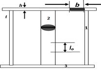
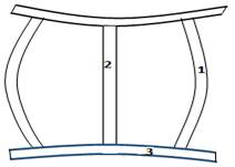
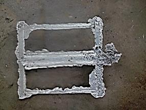
Cutting was made through to section the centre round bar into half, the relaxation of the compressive stresses in buckled thin bars in Figure 2 (b), causes change in length (Δl) which was obtained with steel rule to determine the thermal strain. Figure 2a is the sample immediately after mould shake-out to room temperature.
|
Figure 2 (a). Sample, immediately after mould shake-out to room temperature |
Figure 2 (b). Sample, distorted after cooled |
Coolant was used to cool the samples during cutting to prevent induced additional thermal stresses. The process flow of the thermal analysis is as shown in Figure 3.
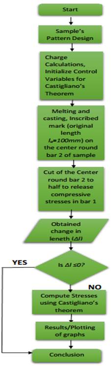
Figure 3. A process flow chart for the thermal stress analysis
Calculation of thermal stresses
After casting, the bars will not cool uniformly due to joint of different sections and thickness. Consequently, stretching stresses will appear in the centre bar and compression stresses in the external bars respectively.
The calculation of the internal tension is made by using Castigliano’s theorem [6]. Thus, between the force and the moment the following relationship was obtained Eq. (1):
![]() (1)
(1)
Where: F - force; M0 - moment; l3 - length of rectangular bars; l2 - centre round bars; l - side round bars.
If the middle bar is sectioned, this will elongate with Δl. The elongation can be determined by Eq. (2):
![]() (2)
(2)
Where: 2l3 – is the length of
the perpendicular bar; 2l – length of the thin and thick bar; I1 –
inertia moment of the thin bar ![]() ;
I3 - inertia moment of the perpendicular bar
;
I3 - inertia moment of the perpendicular bar![]() ;
S1 – area of the thin bar in cross section; S2 – area of
the thick bar in cross section; E – elastic modulus of AL6063.
;
S1 – area of the thin bar in cross section; S2 – area of
the thick bar in cross section; E – elastic modulus of AL6063.
The value of F and M0
determined by the above equations was used to calculate the internal tension (![]() )
and compression (
)
and compression (![]() )
in the bars, Eq. (3-5):
)
in the bars, Eq. (3-5):
![]() (3)
(3)
![]() (4)
(4)
![]() (5)
(5)
Where: W1 and W3 are the resistance modulus of the thin and perpendicular bar, respectively.
The equations from resistance modulus are presented in Eq. (6-7):
![]() (6)
(6)
![]() (7)
(7)
Where: d1 – diameter of the thin bar; b, h – the width and the height of the perpendicular bar cross section respectively.
The Eq. (8) below was generated with curve fitting method for predicting thermal stresses in cylindrical castings aluminium.
![]() (8)
(8)
![]() (9)
(9)
By comparing Eq. (8) with Eq. (9) we obtained:
![]()
![]()
![]()
![]()
Results and Discussion
The chemical composition of the aluminium alloy is presented in Table 1.
Table 1. The chemical composition of the aluminium alloy
|
Chemical element |
*Standard composition (%) |
AL6063 composition (%) |
|
Manganese (Mn) Iron (Fe) Magnesium (Mg) Silicon (Si) Zinc (Zn) Chromium (Cr) Copper (Cu) Other (Each) Aluminium (Al) |
0.0-0.35 0.45-0.90 0.30-0.70 0.0-0.10 0.0-0.10 0.0-0.10 0.0-0.10 0.0-0.05 Balance |
0.5 0.5 0.6 0.3 0.4 - - 0.1 Balance |
*Source: BS EN 573-3, 2015
The composition in Table 1 can be used to compare with the properties of a typical Aluminium - Magnesium - Manganese alloy in ‘as cast’ condition.
The computed results of compressive stresses, and tensile stresses with respect to pouring temperature, change in length are shown in Table 2.
Table 2. Result of measurement of change in length (Δl), pouring temperature, computed compressive stresses and tensile stresses
|
Sample |
Pouring temperature (0C) |
Change in length Δl (mm) |
Compressive stresses in the thin bar σ1 (MPa) |
Tensile Stresses σ2 (MPa) |
|
A |
680 |
0.00 |
No Value |
No Value |
|
B |
720 |
1.00 |
-192.6484 |
18.8475 |
|
C |
750 |
2.00 |
-385.2969 |
37.6951 |
|
D |
800 |
3.20 |
-577.9454 |
56.5426 |
|
E |
850 |
4.00 |
-770.5938 |
75.3902 |
The experimental results obtained for the thermal stresses of aluminium alloy casting have been computed and plotted in graphs. A series of results were obtained for the thermal stresses at different pouring temperature, with the thickness of the centre bar kept constant at 40 mm. From the equation (5, 6 and 7) above tensile stresses in centre thick bar, perpendicular rectangular bars and compressive stresses in thin bars were computed.
The variations of these stresses with pouring temperatures are presented in Figure 4 (a) to 4 (b). Similarly, thermal stresses were computed when the pouring temperature was kept constant at 7200C, while the centre bar diameter was varied in the thickness range of 20 mm, 30 mm, 40 mm, 50 mm, and 60 mm. The stress behaviour in the specified range are also presented in Figures 4 (a) to 4 (b).
Thermal stresses at different pouring temperature with constant thickness (40 mm)
Figure 4 (a) and (b) shows the response of the thermal compressive tensile stresses in the thin bars (side members) and thick (centre bar) to the varying pouring temperature.
Figure 4 (a). Bar chart showing the compressive stress in thin bar versus pouring temperature
It was observed from Figure 4 (a), the higher the pouring temperature, the higher the compressive stresses in the thin bars. This effect can be attributed to the variation in wall thickness of the casting and thermal gradient. Thus, during cooling of the joint walls CET samples, the thin side bars solidified faster, and become compressed, while the thick centre bar still in liquid state and continue to stretch.
Higher pouring temperature result in high thermal gradient within the casting system, causing more stretching stresses in the hot liquid zone (centre core of the thick bar).
The rectangular bridged bars which are already in solid state further hinder the free end expansion of the thin side bars, enabling contraction of the thick centre bar. Hence more compressive stresses are induced in the thin side bar. While tensile stresses are very high in the thick centre bar.
Figure 4 (b). Bar chart showing the tensile stress in thick bar versus pouring temperature
From Figure 4 (b), it is shown that when the pouring temperature was increased the thermal tensile stress also increased steadily from 18.8475 to 75.3902 Mpa at 720 to 850 0C respectively. At 680 0C, the casting was short-run.
Thermal stresses at different thickness with constant temperature (720 0C)
Figure 5 (a) and (b) shows the variation of compressive stresses and tensile stresses with changes in thickness of centre bar at constant temperature of 7200C.
Figure 5 (a). Bar chart showing the compressive stress in thin bar versus diameter of thick bars at constant pouring temperature
From Figure 5 (a), it is shown that the compressive stress decreased with increased in thickness of the centre bar, from 403.086 to 19.8127 Mpa at 20 mm to 60 mm. This is because as thickness continues to increase at constant temperature, tensile stress is much more severe in the thick centre bar and the bridged rectangular bars across the end of the three round parallel bars can no longer hinder the expansion of the bars, thereby causing little compressive effect in the bars.
The centre core of the thick centre bar is still in the liquid phase which result in more tensile stress. This tensile stress stretched the side thin bars, after solidification have completed, instead of the compression of the thin bars, rather they are relaxed.
From Figure 5 (b), it shows that the thermal tensile stresses increases with increased in the thickness of the centre bar.
Initially the graph was nearly steady from 20 mm to 30 mm and increased steeply from 30 mm to 50 mm and become steady again. This is because the thickness of sample A and B are nearly equal, irrespective of the geometry. So thermal gradients in the casting is not high. As thickness continues to Increase thinner part begin to solidify faster than thicker section. Therefore, this result to rapid increase in thermal stress from sample B to D.
Figure 5 (b). Bar chart showing the tensile stress in thick bar versus thickness at constant pouring temperature
Quality assessment of the castings
For aluminium alloys, the optimum pouring temperature range is 7000C to 7500C. At temperatures higher than this range, the casting results in large crystals, low strength and gases are entrapped in the castings, leading to defects known as blowholes. The best surface finish was obtained at the pouring temperature range of 7200C - 7500C. At higher temperatures, cast with sticky sand and very rough surfaces were obtained.
The degree of surface finish deteriorated as the pouring temperature increases as shown in Figure 6 (b) below.
|
Figure 6 (a). Incomplete filling of the mould at 6800C (Low fluidity) |
Figure 6 (b). Cast sample at 8500C with high shrinkage effect |
|
|
|
The cast produced at pouring temperature 7200C were free from internal defect. This implied that the temperature were sufficient.
While the cast produced at higher pouring temperature (800 and 8500C) were found to have either inclusions or dross and gas holes. These defects may be as a result of turbulence flow condition of the molten metal as it is poured through the gating system into the mould.
Generation of stress predicting function by curve fitting method
Figure 7 represents the plot of the value of tensile stress in the centre round bars against the diameter of the bars. With this graph equation (8) was generated.
Figure 7. A graph showing the relationship between the tensile stresses in thick bar versus thickness at constant pouring temperature (7200C)
The generated equation can be use to determine thermal tensile stresses of cylindrical bars of as – cast aluminium alloys before post casting operations.
Conclusions
From the experiment of thermal analysis assessments, it was found that for aluminium AL6063, the optimum pouring temperature range is between 720 0C and 750 0C. This is the region where good quality casts are produced with minimum thermal stresses.
The pouring temperature which gave the minimum thermal stresses in the casts, is 720 0C with stress value of 18.8475 Mpa tensile in the thick bar and -192.6484 Mpa compressive in the thin bar. Thus, it can be conclude that the higher the pouring temperature, the higher the induced thermal stresses.
Optimization of this pouring temperature (7200C) on varying wall thickness (20, 30, 40, 50 and 60 mm diameter) produced tensile stresses with the following value (121.763, 14.2911, 22.1026, 29.8927 and 31.3854 MPa) respectively. These values were used to generate a model to predict subsequent tensile stress values for higher thickness casting. The result confirmed that the value stress obtained were within the range of 7200C and 7500C.
Finally, to minimize thermal stresses in AL6063 cast, it is advisable to pour at temperature little above the melting point.
References
1. Ankur S., Mould cavity layout optimization in sand casting, Unpublished M.Tech. Dissertation, 2009, p. 8.
2. Mahipal S., Manjinder B., Rohit S., Hitesh A., Behaviour of aluminium alloy castings under different pouring temperatures and speeds, International Journal of Scientific & Engineering Research, 2013, p. 1497-1498.
3. Campbell J., A textbook on Castings, Elsevier, 2001, p. 259-260.
4. Lindberg R.A., Processes and materials for manufacture, 2nd Edition, Allyn and Bacon Inc. Boston, London, Sydney and Toronto, 1997, p. 91-96.
5. Lancer N.C., Guidelines for establishment of foundry, MIR Publishers Moscow, 1981, p. 72-75.
6. Stefanescu F.L., Neagu G., Materials casting and solidification, Practice Aspect, 2006, p. 48-54.
7. Lu J., Handbook of measurement of residual stresses, SEM, Bethel, 1996, 1, p. 319-322.
8. Lyman T., Metals Handbook, 8th Edition, American Society for Metals, Ohio, 1961.
9. Metzger D., New K.J., Dantzig J., A sand surface element for efficient modelling of residual stress in castings, Journal of Applied Mathematical Modelling, 2001, 25 (10), p. 825-842.
10. Mohsen S., Sten J., The effects of casting parameters on residual stresses and microstructure variations of an Al - Si cast alloy, The 62nd Annual Denver X-ray Conference (DXC), International Centre for Diffraction Data (ICDD), Westminster, Colorado, U.S.A, 2009, p. 553-560.
11. Tebedge N., Alpsten G., Tall L., Residual-stress measurement by the sectioning method, Exp. Mech., 1973, 13 (2), p. 88–96.