Engineering, Environment
Development of an adjustable multi nut tighter or remover for car tyre
Oluwole Timothy OJO1, Temitope Olumide OLUGBADE2*
1Departmentof Industrial and Production Engineering, School of Engineering and Engineering Technology, Federal University of Technology, PMB 704, Akure, Ondo State, Nigeria
2Department of Mechanical and Biomedical Engineering, City University of Hong Kong, Kowloon, Hong Kong, PR China
E-mail(s): 1wolex025@gmail.com; *2tolugbade2-c@my.cityu.edu.hk
* Corresponding author, +85260645889
Received: December 05, 2017 / Accepted: May 24, 2018 / Published: June 30, 2018
Abstract
An adjustable multi nut tighter or remover for car tyre (with 114.3 PCD) was developed. The need to loosen and tighten car wheel nuts with little application of force (torque) and time spent is of great importance to most car users. Operation with the existing common instruments like ratchet, socket and impact wrench is quite tedious and time consuming. This study was aimed at designing and fabricating a device that will remove and tighten four-wheel nuts of car tyre simultaneously. The design was done using Solidworks CAD software. The device was successfully fabricated, and performance evaluation was carried out. The tightening and loosening of nuts were done with ease as evident from the results obtained. From the performance evaluation of the developed machine, it took 65 seconds to loosen four nuts and 75 seconds to tighten the nuts and the loosening and tightening process were reduced by 41% and 38% respectively compared to using L shaped wrench. Ergonomics consideration was put in place in designing this device as it can be used with ease by both man and woman. The device is also easy to maintain, easy to handle and able to remove and tighten four-wheel nuts of car tyre at once.
Keywords
Multi nut; Car tyre; Ergonomics; Tighter; Remover; Wrench; Design; Force; Efficiency
Introduction
The demand for adjustable multi nut tighter and remover in large quantities is on the increase due to its ability to remove or tighten four-wheel nuts from a car tyre at a time with less application of force. Cars are provided with tyres for moving from one point to another by changing and maintaining direction of travel, absorbing road shocks, supporting vehicle weight and transferring traction and braking forces to the road surface. Sometimes the vehicle tyres develop some problems and there is the need for the driver to remove the tyres and fixes the problem. The problem to tighten the nuts does occur most times even if the nuts are successfully removed. And the driver’s safety is also at risk if the required torque is not applied in tightening the nuts [1].
The box spanner or torque wrench is the most commonly instrument used to tighten or remove the nuts from the bolts in the wheel of a vehicle but the tightening and removing process of the wheel nuts is quite tedious. Nevertheless, due to the difficulty in applying the required torque to remove the nuts, most of the time, driver rely on the tow truck and available nearest mechanic to solve the problem. This mostly happen to the female and the aged drivers. The setbacks of this instrument are time waste and force needed [2]. It is often rare to get tool that is easy to use to remove the nuts in most Nigeria automotive market. The time to open a car’s tyre nut is too long and leads to waste of time of car users with utilization of high force. To eliminate the time waste and high force needed, a device that is manually operated by hand due to the epileptic supply of electricity have been devised to remove four-wheel nuts at a time with reduction in the force applied for the operation. It can open and tighten the wheel with the same tool easily. The tool is simple in design, easy to use and easily portable along with the vehicle.
This device operates on the principle of gear arrangement system. It consists of five gears in which the centre gear called pinion (driver) gear is used to drive four other gears (driver gear) that meshed with it. This work may have solved the problem of four nut removal and force usage utilization to some extent without the application of an electric motor or any hydraulic and pneumatic devices.
Quite several multi nut tighter or remover devices have been developed in the present decade having similar construction features such as sun gear, planetary gear, shaft carrying the box spanner etc. Some of these devices include those that are manually, electrically and pneumatically controlled which are in commercial production around the globe. Nitesh. et al. [3] designed and fabricated a four-wheel opening spanner. In the work, each of the four nuts is losing/tighten individually by simultaneously applying the spanner/lever. Either with the help of mechanism developed that one can loosen or tighten all four nuts at a time and at the single stroke of the hand operated or motor operated lever. This is done by adjusting the five gears between two side plates operated only by lever or input pinion shaft.
Similarly, Azman et al. [1] designed and fabricated a vehicle all-wheel- nut remover. Ergonomics was put into consideration in the design because the users have to support it with their hand during use which could be stressful and time consuming. Sivabalan et al. [2] designed and fabricated an adjustable unified wheel opener. Bevel gear arrangement was used for actuating the four socket spanners at a time. Twelve driven gears and one pinion gear were used. The cam and follower mechanism were used for making the project adjustable. The result emphasized the importance of radial as the follower moves in the direction perpendicular to the cam axis. Several mechanisms have been designed in the past for car tyre tightening and removing among which are 6 in 1 all-nut remover for automobile wheels [4], four wheeler opening spanner [5], computer assisted impact wrench for a car wheel nuts puller [6], all wheel nut remover for automotive [7], heavy duty gears [8], multi nuts removal tool [9], spur gear in different geometric conditions [10], conceptual vehicle all wheel Nuts remover [11], multinut opener cum tightner for four wheeler [12], cam- controlled planetary gear trains [13], multi-nut operating tool using catia and ANSYS [14], tyre nut remover with 114 PCD [15].
The existing car tyre remover and tighter are faced with some challenges; the heavy weight of the device which makes its operation difficult for female or aged car users, the device requires large storage space, and electrical power is not accessible at every place where it is necessary to remove wheel nuts from car tyres. The existing wheel nuts remover is too heavy, and it is not convenient to be a portable wheel nuts remover. It is hard to be used because of the heavy weight. It cannot perform well to remove the car wheel nuts and some of the wheel nuts remover cannot remove all the four nuts at a time. Hence, there is need to design a device that can address the shortcomings. Few works have been done on adjustable multi-nut tighter or remover which can reduce the time spent in changing or replacing flat car tyres, and at the same time performing the same function with little application of force.
In the present work, an adjustable multi nut tighter or remover for car tyres which can remove or tighten four-wheel nuts at a time with less application of force was designed and fabricated, to replace the existing tool which is tedious to use. The performance evaluation of the device, which can be operated by both men and women, was also carried out.
Material and method
Materials selection criteria
The materials used for the design of the various machine components are based on the type of force that will be acting on them, expected work or function, the environmental conditions in which they will function, useful physical and mechanical properties, cost and availability in the local market or the environment.
Figure 1 illustrates the working procedures adopted in fabricating the developed machine.
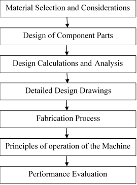
Figure 1. Working procedure for the developed Machine
In Figure 1 working procedure consists of the material selection and consideration, design of component parts, design calculations and analysis, detailed design drawings, fabrication process, principles of operation of the machine and performance evaluation.
Design of the component parts
The gear housing accommodates the gear system used for the work and it is supported by the pillar guide. The gear housing was designed, and the area was determined based on the length (L) and breadth of the plate (B), Eq. (1).
![]() (1)
(1)
Where: Ag - the area of the gear housing, L - the length of the plate, and B - the breadth of the plate.
The device was designed for 114.3 PCD (centre distance between the driving and driven gears is 57.15 mm). The driver (gear) and the driven (pinion) was designed and the torque required for removal of one (1) nut is 80 Nm. Spur gears were selected due to ease in design and manufacturing. Apart from this, the velocity ratio (V.R) in spur gear is constant. Keeping the above factors in mind and using medium carbon steel grade for the gear and pinion and the design calculation were performed. The pitch diameter (Dp) was designed based on the number of pinion teeth (Np) and diametral pitch (Pd), Eq. (2),
![]() (2)
(2)
Where: Dp - the pitch diameter, Np - the number of pinion teeth, and Pd - the diametral pitch.
Table 1 summarizes the properties and parameters of the material used for the design of the gears (medium carbon steel i.e. EN 8).
Table 1. Properties and parameters for the gear design
|
S/N |
Design Properties |
Parameters |
|
1 |
Ultimate tensile strength (δu) |
550 N/mm2 |
|
2 |
Yield strength (δy) |
280 N/mm2 |
|
3 |
Young modulus (E) |
200 GPa |
|
4 |
Poisson ratio |
0.3 |
|
5 |
Brinel hardness |
255 HB |
|
6 |
Pitch circle diameter (PCD) |
114.3 mm (for car tyre) |
|
7 |
Torgue required to remove nuts (T) |
480 Nm |
|
8 |
Average force by human (F) |
500 N |
|
9 |
Pressure angle (Ø) |
20° |
|
10 |
Number of teeth of the driven gear (NG) |
15 |
|
11 |
Number of teeth of the driver gear (NP) |
10 |
The ultimate tensile strength, yield strength, young’s modulus, poisson ratio and other properties and parameters are carefully selected before the gear designs for effective performance. The pitch diameter, together with the number of pinion teeth (Np) was then used to determine the circular pitch (P), Eq. (3).
![]() (π
= constant =3.142) (3)
(π
= constant =3.142) (3)
Where: P - the circular pitch, Dp - the pitch diameter, and Np - the number of pinion teeth.
The gear ratio (G.R) and velocity ratio (V.R) was designed using Eq. (4-5).
![]() (4)
(4)
![]() =
= ![]() (5)
(5)
Where: G.R - the gear ratio, NG - the number of teeth of the driven gear, NP - the number of teeth of the pinion, V.R - the velocity ratio.
The radial force applied and the tangential force was determined using Eq. (6-7).
![]() (6)
(6)
![]() (7)
(7)
Where: Fr - the radial force applied, Ft - the
tangential force applied, and ![]() - the pressure angle.
- the pressure angle.
The stress at the base of the involute profile (δt) was designed using Eq. (8).
![]() (8)
(8)
Geometry factor for spur gear (J) was designed using Eq. (9).
![]() (9)
(9)
Where: J - the geometry factor for spur gear, δt - the stress, Pd - the diametral pitch, and F - the face width.
Using the speed of the pinion gear (assume humans can turn the pinion gear at the rate of 30 rpm) (N) and the torque applied to remove the nuts (T), the power transmitted by the pinion gear (Pp) was designed, using Eq. (10).
![]() (10)
(10)
The torque transmitted by the driven gear (Tg) is therefore designed using the dear ratio (G.R), Eq. (11).
Where: Pp - the power transmitted by the pinion gear, N - the speed of the pinion gear, T - the torque applied and Tg - the torque transmitted by the driven gear.
The
permissible bending stress (δb) for the gears is given in Eq. (12) [4] based on the ultimate tensile strength of
the gear material ( ).
).
![]() (12)
(12)
Where: ![]() -
the permissible bending stress, and
-
the permissible bending stress, and ![]() -
the ultimate tensile strength of the gear material.
-
the ultimate tensile strength of the gear material.
To design the effective loading on the gear teeth (Feff), the combined shock and fatigue factor (Ka = 1.25), load distribution factor (Km = 1.2), tangential force applied (Ft = 469.85N) and the dynamic factor (Kv) were considered using Eq. (13).
Feff = ![]() (13)
(13)
Where: Feff - the effective loading on the gear teeth, Ka - the combined shock and fatigue factor,
Km - the load distribution factor, and Ft - tangential force applied, and Kv - the dynamic factor.
The beam strength (Fb) was designed based on the Lewis form factor (Y), face width (F), permissible bending stress (δb) and module (m), using Eq. (14).
![]() δb (14)
δb (14)
The available factor of safety (FOS) is then determined by the beam strength (Fb) and the effective loading on the gear teeth (Feff), using Eq. (15).
![]() (15)
(15)
Where: Fb - the beam strength, m - the module, F - the face width, Y - the Lewis form factor,
δb is the permissible bending stress, FOS - the factor of safety.
The design is safe if the available factor of safety is more than 1.5 and not safe if it is less than 1.5. The available factor of safety obtained is 2.42 which is higher than that of the required factor of safety, hence the design of the gear pair is safe. For shaft design, in actual practices, the shafts are subjected to shock and fatigue loading. Hence, in design of the shaft, the shock and fatigue factor are accounted by using the factor knows as combine shock and fatigue factors. Putting into consideration the speed (N) and the ultimate tensile strength (Su), the power transmitted by the input shaft to the pinion gear (Pi) and the output shaft (Po) are determined using the input torque (Ti) and the output torque (To) respectively. The diameter of the input shaft (D) and the output shaft (d) are then determined. Theoretical efficiency of the machine (ηT) is then calculated (ratio of output and input power).
Detailed design drawing
The design drawing of the developed machine was done using Solidwork software. The detailed design drawings made the fabrication process and performance evaluation easy and faster. It consists of all the machine parts including handle (input shaft), hexflange nut, gear housing plate, driven (planetary gear), output shaft, socket wrench, pinion (driver) gear, bolt and frame.
Figure 2 shows the isometric view of the 3D model of the adjustable multi nut tighter and remover.
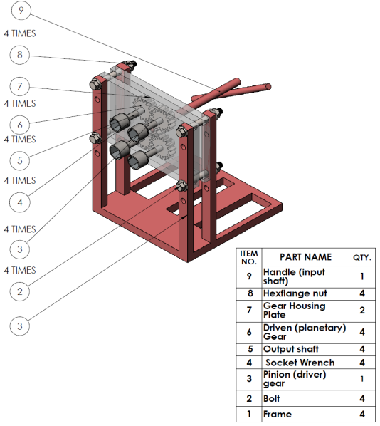
Figure 2. Isometric view of the 3d model of the adjustable multi nut tighter and remover
The exploded view of the device is presented in Figure 3 while the orthographic view of the device is shown in Figure 4.
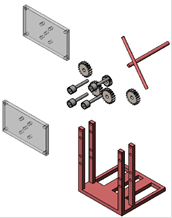
Figure 3. Exploded view of the device
|
|
|
|
|
|
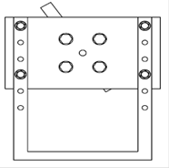
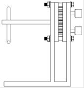
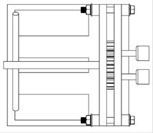
Figure 4. Orthographic view of the device
Results and discussion
The area of the gear housing and the centre distance between the gears were designed to be 640350 mm2 and 57.15 mm respectively. The machine was designed for 114.3PCD. Due to the convenience and ease in design and manufacturing, spur gears were selected for the design, similar results were obtained in the past works [1, 3-4].
Table 2 illustrates the summary of design factors and the corresponding design values while the final driver and driven gear parameters are tabulated in Table 3.
Table 2. Design factors and considerations
S/N |
Design Factors and Considerations |
Parameters |
1 |
Area of the gear housing |
640350 m2 |
2 |
Centre distance between the gears |
57.15 mm |
3 |
Torque required for removal of one (1) nut |
80 Nm |
4 |
Pitch diameter (DP) |
42.48 mm |
5 |
Circular pitch (P) |
13.35 mm |
6 |
Gear ratio (G.R) |
1.5 |
7 |
Velocity ratio (V.R) |
0.67 |
8 |
Radial force applied (Fr) |
171.01 N |
9 |
Tangential force (Ft) |
469.85 N |
10 |
Geometry factor for spur gear |
0.0964 |
11 |
Stress at the base of the involute profile (δt) |
16.88 N/mm2 |
12 |
Power transmitted by the pinion gear (Pp) |
1.508 kW |
13 |
Torque transmitted by the driven gear (TG) |
720 Nm |
14 |
Permissible bending stress for both gears (δb) |
183.33 N/mm2 |
15 |
Effective loading on the gear teeth (Feff) |
1.296 kN |
16 |
Beam strength (Fb) |
3.130188 kN |
17 |
Available factor of safety (FOS) |
2.42 |
18 |
Power transmitted by the input shaft (Pi) |
1.508 kW |
|
19 |
Diameter of the input shaft (D) |
19.749 mm |
|
20 |
Power transmitted by the output shaft (Pi) |
1.131 kW |
|
21 |
Diameter of the output shaft (d) |
22.607 mm |
22 |
Theoretical efficiency of the machine (ηT) |
75 % |
Table 3. Parameters of the driver and driven gear
|
S/N |
Parameter |
Formula |
Driver Gear (mm) |
Driven Gear (mm) |
|
1 |
Base pitch (Pb) |
PCOSØ |
12.54 |
12.23 |
|
2 |
Addendum (ha) |
1/P |
4.248 |
4.248 |
|
3 |
Dedendum (hf) |
1.2/Pd |
5.0997 |
5.0997 |
|
4 |
Base radius (Rb) |
DpCOSØ/2 |
19.96 |
29.19 |
|
5 |
Clearance |
0.2/
Pd |
0.8516 |
0.8516 |
The diameter of the input (D) and output shaft (d) are approximately 19.75 and 22.61 mm respectively, which is adequate for the mounting of the square end of the socket spanner [3]. The theoretical efficiency of the machine (ηT) (ratio of output and input power) is obtained to be 75%.
The ultimate tensile strength, yield strength and Young modulus are obtained to be 550 N/mm2, 280 N/mm2and 200 GPa respectively. These results are in line and within the range of a good design when compared with the previous results [2, 4-5]. Power transmission is an important factor in any design. The power transmitted by the input shaft (pinion gear) and output shaft are 1.508 kW and 1.131 kW, which is similar to the results obtained in the past [4].
Factor of safety was considered in the design for reproducibility and machinability. The design is safe if the available factor of safety is more than 1.5 and not safe if it is less than 1.5. The available factor of safety obtained is 2.42 which is higher than that of the required factor of safety, hence the design of the gear pair is safe.
It should be noted that for shaft design, in actual practices, the shafts are subjected to shock and fatigue loading. Hence, in design of the shaft, the shock and fatigue factor are accounted by using the factor knows as combine shock and fatigue factors. The permissible bending stress for both gears, effective loading on the gear teeth and stress at the base of the involute profile is designed to be 183.33 N/mm2, 1.296 kN and 16.88 N/mm2 respectively.
Table 4 shows the summary of the time taken to loosen and tighten 4 nuts for L shaped wrench and adjustable multi-nut tighter and remover, together with the torque applied.
Table 4. Performance Evaluation using Nissan Sunny Car
|
Tool |
Time (s) |
Torque applied (Nm) |
|
|
To loosen 4 nuts |
To tighten 4 nuts |
||
|
L shaped wrench |
110 |
120 |
560 |
|
Adjustable multi-nut tighter and remover |
65 |
75 |
480 |
|
% reduction in time spent by adjustable multi-nut tighter and remover (Nissan sunny car as a case study) |
41 % |
38 %
|
|
Performance evaluation was carried out after the designing and fabrication process of the adjustable Multi-nut tighter and remover had been completed. This was done to determine the time taken to lose and tight four-wheel nuts of car tyre.
The performance evaluation was carried out using a Nissan sunny car. At the end of using the adjustable multi-nut tighter to carry out the operations, conventional tool (L shaped socket wrench) was also used. From the result obtained above, it clearly shows that using the adjustable multi-nut tighter or remover to remove the four car wheel nuts has reduced the time spent in the process of loosening by 41 % and tightening by 38 % with less application of torque compare to when L shaped wrench is used.
Conclusions
An adjustable multi nut tighter or remover for car tyre (with 114.3 PCD) was developed. The design of the adjustable multi nut tighter or remover was completed, and the performance evaluation has been carried out successfully. From the results obtained during the performance evaluation, it clearly shows that the device can conveniently removes and tightens four-wheel nut of car tyre with little application of force and time spent. Hence, the machine can be operated by both men and women with ease.
A detail feasibility study is however recommended to find alternative materials that are lighter in weight to further reduce the weight of the device.
Also, this study should be further subjected to improvement and modification by inculcating free wheel to each of the socket wrench. This will overcome the challenges of one nut tightening faster than the rest. Provision for adjustable gear arrangement system will also make the wheel nuts to fit in perfectly into the socket wrench.
Acknowledgements
The authors would like to appreciate the effort of Mafo David who contributed immensely towards the success of this work.
References
1. Azman M., Sulaiman N., Design and fabrication of vehicle all wheel nut remover. International journal of computer science and electronics engineering, 2003, 1 (3), p. 381-384.
2. Sivabalan R., Vignesh M., Vairamuthu S. and Hameed M.S., Design and fabrication of adjustable unified wheel opener, International Journal of Innovative Research in Science, Engineering and Technology, 2014, 3 (2), p. 516-518.
3. Nurfarahin B. S., Improvement of wheel nut remover, final year project, Department of Mechanical Engineering, University of Teknikal Malaysia Melaka, 2013, p. 3-4.
4. Bhanage A. and Bhanage V., Design and fabrication of 6 in 1 all-nut remover for automobile wheels, International Advanced Research Journal in Science, Engineering and Technology (IARJSET), 2016, 3 (1), p. 33-38.
5. Gomesh N., Chawhan P.R., Thakre, A. V., Rahangdale, R.T. and Narnware V.S., Design and fabrication of four-wheeler opening spanner, International Journal for Science Research and Development (IJSRD), 2015, 3 (2), p. 1569-1570.
6. Mukhtar M. and Hussaine M.H.P., Design improvement and computer assisted fabrication on the impact wrench for a car wheel nuts puller in automotive industry, Australian Journal of Basic and Applied Science, 2014, 4 (1), p. 548-553.
7. Bhanage A. Bedse S., Devar K., Batte V., Dixit, K., Design and development of all wheel nut remover for automotive, International Journal of Applied Engineering Research, 2015, 10 (7), p. 17631-17641.
8. Kumar S.S., Shiva B., Heat treatment on en 8 and en 353 for heavy duty gears, International Journal of Mechanical Engineering and Robotics Research, 2014, 3 (2), p. 245-250.
9. Avinash S., Bharaneedharan M., Design and fabrication of multi nuts removal tool, International Journal of Scientific Research, 2014, 3 (11), p. 238-241.
10. Kumer P., Raghuvanshi, H., Design and analysis of spur gear in different geometric conditions, International Journal of Engineering and Advanced Technology, 2013, 3 (2), p. 230-236.
11. Abdullah M, Shaharuzaman A., Development of conceptual vehicle all wheel nuts remover, International Conference on Design and Concurrent Engineering, 2012, p. 199-202.
12. Chowki V., Mhatre S., Shekhawat Y.S, Yadav U. and Jhadav S., Multinut opener cum tightner for four-wheeler, International Journal of Scientific and Research Publications, 2016, 6 (3), p. 319-328.
13. Hsie W., An experimental study on cam- controlled planetary gear trains, Science direct journal, 2007, 24, p. 513-525.
14. Prashanth P.M., Akhil R.M.P., Manjunath B., Shaikh S, Gaded, N., Modelling and analysis of a multi-nut operating tool using catia and ansys, Journal of Mechanical Engineering and Automation, 2017, 7 (5), p. 139-144.
15. RahmanA.B., Aziz A., Improvement and optimization of tyre nut remover with 114 pcd, 2008, University of Malaysia, Pahang.