Engineering, Environment
Design and fabrication of low-cost electrical resistance based metal melting furnace for casting applications
Vijaya Sekhar Babu MERIGA1*, Ajay Dev BOYINA2 and Chittibabu VANDANA3
1,3Department of Mechanical Engineering, GMR Institute of Technology, Rajam, Andhra Pradesh, India
2Axis Control Technologies, Eluru, Andhra Pradesh, India
E-mail(s): 1 drmvsbabu@gmail.com; 2 ajaydevb@gmail.com; 3 chittibabu.v@gmrit.org.
* Corresponding author: email: drmvsbabu@gmail.com, phone: +918941251592.
Received: June 30, 2017 / Accepted: April 03, 2018 / Published: June 30, 2018
Abstract
Casting is an ancient technique used for making various parts. There are various types of furnaces used for melting metals and alloys, working on different principles. In this work, an electrical resistance based low-cost furnace is planned to fabricate for melting metals. The objective is to design and fabricate an electrical metal melting furnace of 3.5 kW rating with operating temperatures up to 10000C. Further, the furnace was aimed to be able to hold the melt for required amount of time. Both electrical and mechanical aspects of furnace design were presented. Finally, the fabricated furnace operation as discussed and its heating performance was tested by melting aluminium. Its operation was discussed to suit the heating requirements for various metals and alloys.
Keywords
Melting furnace; Aluminium melting; Resistance based furnace; Low-cost furnace; Metal matrix composites; Stir-casting; Casting; Electrical furnace
Introduction
The developing and under developed countries may not allocate significant funds towards the development of science and technology. Therefore, researchers and scientists look for alternate ways of getting funds. Further, they put efforts to minimise the cost of the projects to the possible extent. Bala [2] stated that for a nation to advance technologically, it must be able harness, convert its mineral resources and fabricate most of its equipment and machines locally. In these lines, the work presented in this paper is aimed at design and fabrication of low-cost electrical resistance based metal melting furnace to fulfil the metal melting requirements in the research and academic laboratories.
Metals are flexible components whose fields of use are wide in human lives. Ostwald and Munoz [3] and Gilchrist [4] found that the melting and heat treatment of metal in foundries is very important in manufacturing process. Oyawale and Olawale [5] designed and constructed an electric arc furnace to melt 5kg of steel/cast iron scraps, using locally produced Soderberg electrodes. Authors carried out tests on the furnace and conformed that it has taken 60 minutes to heat up the furnace to 1200 0C. Further, the furnace took about 95 minutes to melt the first charge of 2kg resulting in a melting rate of 21.05g/minute.
Bayindir [6] designed and constructed an electrical furnace with an automatic control to fire ceramic products. Abed [7] manufactured a gas furnace using locally sourced materials which had a heating rate of 25 0C/min and attained temperature in the heating zone as high as 1000 0C in the burning chamber and 700 C° in the inner pot, while Bala [2] carried out the design analysis of an electric Induction furnace for melting of aluminium scrap. Sahoo, Rout [8] expressed that there are various heating methods are available. There might be numerous strategy for providing heat to the stock but heat is delivered either by ignition of fuel or electric resistance. By considering cost, security, effortlessness and simplicity of fabrication authors have gone for an electrical resistance heating furnace with indirect heating provisions. Further authors extended their work for fabricating stir casting furnace for melting aluminium.
Sekar, Allesu [9] presented the design and fabrication of stir casting setup for preparing the aluminium, magnesium and copper-based metal matrix composites. In this setup, a nano particle preheating attachment at the top of the furnace was incorporated. It is a direct result of red hot condition with consistent temperature of nano particles infused by push bar into the liquid metal. The stirrer rod composed by variety of speed (0-2000rpm) for blending purpose. Naher, Brabazon [10] designed a novel fast quenched stir caster for handling Al–SiC composites in fluid and semisolid state. Ariff and Zakaria [11] designed an electric furnace based on the analysis of conceptual design. Authors have considered the appearance, the cost included, the heating method, the static weight, the most extreme temperature and the portability of the furnace. From the simulation, it was found that the heat flow due to convection collects the whole space in the furnace and is able to totally melts the aluminium. The process of melting 1kg of aluminium taken is under 45minutes, it is 62.5 % quicker contrasted with the ordinary 2 hours from utilizing conventional technique. The cost of producing this revised plan of electric heater is considerably less expensive since the aggregate cost of materials expected to manufacture this heater is just RM 5160. It gives the most temperate and moderate cost for an effective electric heater (with proficiency of 78.53%) to be utilized as a part of the little scaled craft industries.
Nandy and Jogai [12] stated that the melting furnace life and energy efficiency relies on the proper selection of refractory materials and its performance in the heating conditions. The properties and effectiveness of the refractory decide the degree of heat lost during state condition and storage heat loss during transient condition. The stoppage of furnace operation brought about by refractory failure because of corrosion and mechanical wear prompts to significant effect on energy saving. The decrease in downtime, because of refractory failure, raises the energy saving and it can be accomplished by utilizing phosphate bonded hard refractory materials. A multi-layer lining with optimised execution of layers with the service condition and appropriate establishment enhances the energy effectiveness of a furnace in future. A good quality commercially available furnaces costs from ₹1.5 lakhs to 5 lakhs depending the size and features. In this present work, it is aimed to fabricate a low-cost electrical resistance based metal melting furnace to facilitate the melting of metals in small quantities needed for applications like metal casting, metal matrix composites, etc.
Materials and methods
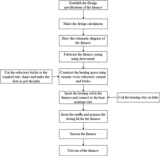
The following are the basic logical steps involved in the design and fabrication of the proposed furnace.
1) Setting the furnace specifications: A furnace of 3.5kW heating capacity was aimed to fabricate. It must be capable to heat metals to about 1000 0C. It enables the furnace to be useful to melt metals whose melting temperatures fall less than 1000 0C. Further, it has to be able to hold the melt at a set temperature for required amount of time. It must accommodate different sizes of crucibles for melting various quantities.
2) Preparation of the list of elements and components required for the furnace: A list of items which are going to be part of the furnace are prepared. The list includes
i. Furnace bricks
ii. Heating wire (heating coil)
iii. Ceramic wool
iv. Refractory cement
v. Sheet metal cabin
vi. Heat resistant wire
vii. Solid state relay
viii. PID controller
ix. K-type thermocouple
3) Making design calculations: Design calculations need to make to determine the specifications of the items in the above list. Finally, check weather, it is able to meet the heating specifications targeted in step – 1. These design aspects are presented in the appropriate subsections.
4) Geometry and layout of furnace: Fix geometry and the layout of the furnace to incorporate the elements with above specifications in to the furnace.
5) Fabrication of the furnace: Fabricate the furnace, make the electrical connections and complete the fabrication process.
6) Seasoning of the furnace: Heating the furnace without charge to about 1200 0C, holding for about 1hour and cooling it the lid in its place. This process removes any moisture in the furnace, bricks, etc., and fixes the geometry of the coils.
7) Test run of the furnace: Melting the metals to test the performance of the furnace.
The following subsections present the components of the furnace and their design aspect.
The workflow in the design and fabrication of the proposed metal melting furnace is shown in the Figure 1.
|
Figure 1. Workflow in the fabrication process of the furnace |
Furnace geometry and layout
All Basic elements of the resistance based electrical furnace are shown in the schematic diagram presented in the Figure 2. It is aimed to use ‘Bilge’ or ‘A’ type cylindrical crucible for melting metals.
|
|
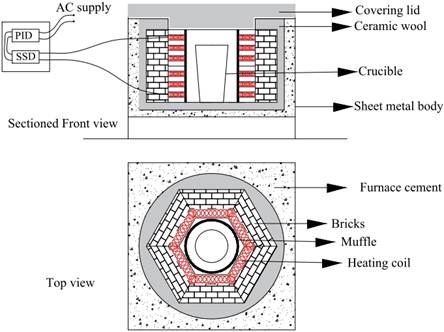
Figure 2. Schematic plan of the electric furnace
Firebricks
Refractory bricks or fire brick is a block of refractory ceramic material used in lining of furnaces and kilns. These bricks need to possess low thermal conductivity, hold heat in the furnace and withstand high temperatures. The fire bricks used for the present electrical furnace are of size 9 x 5 x 4 in. and shown in the Figure 3(a). To arrange the bricks as shown in schematic in Figure 2, these bricks were cut according to the plan shown in Figure 3(b). After cutting, the bricks shown in Figure 3(c) were obtained for use in the furnace. These bricks were arranged to attain the hexagonal heating chamber.
It is planned to have 6 turns of the heating wire passing from top to bottom in the grooves cut in the bricks. A total of 12 bricks were cut and arranged in 2 layers to form the hexagonal heating chamber. So, each layer of bricks will have 3 heating wire turns as shown in Figure 3(b). To facilitate the laying of heating wire in to 6 turns in the chamber, inclined slots were cut in 2 bricks kept one over the other as shown in Figure 3(b). The 3 slots on the brick were cut on the 9 x 5 in faces of the bricks.
|
|
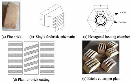
Figure 3. Fire bricks and their preparation
Heating wire
The furnace was planned to operate up to 10000C. Therefore, Kanthal wire was chosen as the heating wire for the electrical furnace. Kanthal is a ferrite-iron-chromium-aluminium alloy. It is a resistance based electrical heating wire which can be used to heat things up to 14000C. Kanthal has high electrical resistivity and very good oxidation resistance. It is widely used as electrical heating elements in high-temperature furnaces for heat treatment, ceramics, glass, steel, and electronics industries. Kanthal wire used in the furnace has a diameter of 2 mm and is shown in Figure 4(a). To build the furnace of 3.5 kW furnace, the following calculations were made based on its electrical resistance.
For a 3.5 kW furnace, the total amount of current drop required across the heating wire, Eq. (1)
![]() (1)
(1)
Where: P - power (in Watts), V - voltage (in Volts), and I - current (in Amperes).
Using Eq. (1), I was obtained as 15.22 A. The electrical resistance of the Kanthal wire is 0.446 ῼ/m as given by the manufacturer. Now, it is required to determine the total length of the wire required to use as heating wire in the furnace for dropping 15.22 A in the furnace.
From Eq. (2), the total length of the wire was found as 33.87m i.e., about 34 meters. It was planned to lay down this 34 m of wire in 6 turns around the hexagonal heating chamber in the furnace. Each of these 6 turns is composed of 6 groove segments, each of length 5.2 inches (132 mm).
![]() (2)
(2)
Where: P - Power (in Watts), I - Current (in Amperes) and R - Total resistance in the wire of length ‘L’ (in meters) i.e., (0.446 x L).
So, the Eq. (3):
![]() (3)
(3)
Where: Lg - total length of grooves (in mm), lg - length of each groove (in mm), Ng - number of groove segments/ turn and n - nounmber of turns.
From Eq. (3) the total length of grooves was obtained as 4752 mm. Therefore, it is required to accommodate the 34 m of heating wire in this 4752 mm long grooves. So, in each groove segment it is required to accommodate 944.44 mm (i.e., 34000/36) of heating wire.
|
|
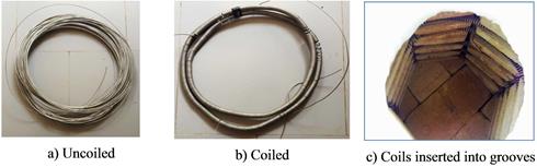
Figure 4. Kanthal heating wire before and after coiling
The groove is made in the square cross section of side 18 mm. If it is assumed to coil heating wire using a 12.5 mm diameter rod on a lathe machine, then the approximate diameter of each coil is 16.5 mm. Then, the length of each coil or wire length in each coil is 51.83 mm (i.e., π x 16.5). Therefore, the number of coils in each groove segment = 18.22 (i.e., 944.44/51.83) Then, the gap between each coil is 7.24 mm (i.e. 132/18.22). The coiled wire may be seen the Figure 4 (b), and the same was given a coil gap of about 7 mm between successive coils. The Figure 4 (c) shows the coiled inserted heating wire in the grooves.
Ceramic wool
Ceramic wool or ceramic fibre blanket is made of ceramic needle like minute particles. It is light in weight, flexible, excellent in fire protection, contain very low thermal conductivity, and store low heat, thermal shock resistant and corrosion resistant. It is a commercially available in various densities, thicknesses, widths and lengths. The ceramic blanket used in the present furnace is 1 inch thick is shown in Figure 5 (a).
Miscellaneous components
Refractory cement or furnace cement is a specially designed and mixed cement product that will withstand extremely high temperatures while maintaining its structural integrity. It was used around the ceramic wool as shown in Figure 2. A sheet metal cabin of size 23 x 23 x 14 in. was prepared to house the elements of the furnace as shown in Figure 2. A heat resistant wire was used to connect the Kanthal heating wire terminals to SSR (solid state relay). It is basically used near the metal melting furnaces to stop the heat progression out of the furnace. A solid-state relay shown in Figure 5(e) rated as 20 A is used in the furnace. Its purpose is an electronic switching device that switches on or off when a small external voltage is applied across its control terminals.
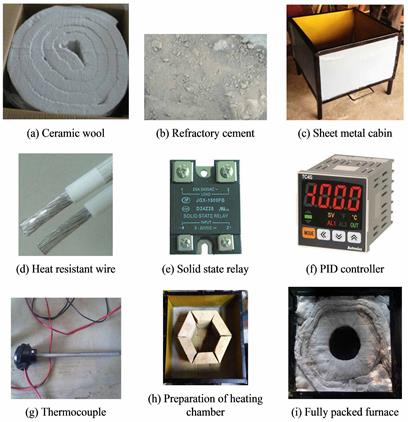
Figure 5. Miscellaneous elements used in the furnace
A K – Type thermocouple (Figure 5 (g)) is used to measure temperatures up to 13000C. It was used to measure the internal temperature of the furnace and fed it to the PID controller. A hole was drilled through the bricks to insert thermocouple and measure the temperature. A PID controller device has a feedback control mechanism. Based on the feedback i.e., temperature from thermocouple, it operates the SSR to control the temperature in the furnace. The PID controller used in the furnace is made of Autonics (TC4S) is shown in Figure 5 (f).
Fabricated setup with electrical connections
Once the components of the furnace are ready, the furnace was fabricated as per the schematic shown in Figure 2. Figure 5 (h) and 5 (i) shows intermediate stages in the furnace fabrication. Figure 6 shows the electrical connections between various elements of the furnace. The negative wire from the power supply is directly given to the heating coil, while the positive wire is connected to a terminal of solid state relay.
|
|
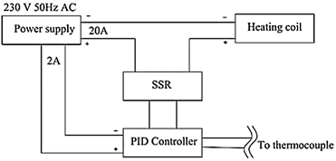
Figure 6. Electrical connections among various components of the furnace
The completely fabricated furnace is shown in Figure 7. Before using the furnace for first time it is required to season the furnace. To season the furnace, the furnace opening was closed without loading it and heated to 1000 0C. Then, it is allowed to cool down normally to room temperature. This process removes any water content or moisture content from the bricks, it hardens the heating coil and permanently fix their shape in the bricks. It also permits the user to check for leakages in the furnace and allows user to check its safety when it was heated to designed temperature.
|
|
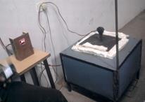
Figure 7. Fabricated induction furnace setup on working
The furnace is not advisable to use without the muffle. Because, the coils are opened to air and are prone to high electric shock. So, it always recommended to use a muffle to cover the coils. Figure 8 (a) shows the hexagonal heating chamber without muffle. Figure 8 (b) shows the PID controller used to control the temperature. A stirring attachment shown in Figure 8 (c) may be used to fabricate metal matrix composites [13-17] to meet various applications [18-21] using this electrical metal melting furnace.
|
|
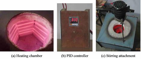
Figure 8. Furnace in working
Results and discussion
Heating performance of the furnace
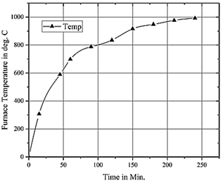
The furnace was tested by melting aluminium and its alloys. The characteristic curves i.e., heating time vs. furnace temperature. Initially, the furnace is loaded with aluminium of 0.5 kg, and as the temperatures were raising, time and temperatures were recorded continuously and characteristic curve was plotted between them and shown in the Figure 9.
|
Figure 9. Heating trend of fabricated electrical furnace. |
Usage
This furnace can be used for melting any metal whose melting points fall below 10000C. All molten metals forms oxides when react with oxygen in air. So, appropriate precautions, protective care, accessories and procedures should be employed during melting metals using the above furnace. This furnace is not suitable for melting metals like magnesium, its melting point is less than 10000C. Complete protection of magnesium melt is required from the air.
|
|
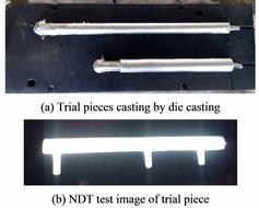
Fig. 10. Trial piece casting and its NDT test.
This furnace is not equipped with such protective accessories. This fabricated furnace was used for casting trial pieces by sand and die castings like ones shown in Fig. 10. The castings were tested using NDT Radiography testing. No Sever casting defects were found. So, it can be concluded that the furnace was able to melt the metal as per the objective. The cost of fabrication was far less when compared with a commercially available equivalent furnace. The cost of the furnace fabricated is about ₹25,000, whereas the commercially available furnace cost is about ₹2, 00,000/-. It is about 15% of the cost of commercially available furnace. The fabricated furnace meets the purpose but may not look attractive like commercially available furnaces.
Conclusion
A low-cost metal melting furnace for melting aluminium and its alloys is designed and fabricated. Both mechanical and electrical parameters were considered in designing the furnace. This furnace heating suitable for melting and holding small quantities of metals whose melting points are less than 10000C like Al, Zn, and their alloys (except magnesium like metals and alloys) for laboratory and research purposes. The heating tests were conducted for melting aluminium and furnace heating performance was analysed by drawing characteristic curve. The heating rate, melting rate are comparable to existing standard furnaces attaining a temperature of well over 700 0C within 100 min and melting the first charge in about 100 minutes. Finally, sample sand and die castings were prepared and tested using NDT radiography testing for casting defects and conformed the lack of defects.
Acknowledgements
We sincerely thank GMR Institute of Technology, Rajam for providing necessary facilities, work force and infrastructure for the successful completion of this project.
References
1. Black J.T. and Kohser R.A., Degarmo's materials and processes in manufacturing, 11th ed. International Student Edition, Wiley, 2013.
2. Bala K., Design analysis of an electric induction furnace for melting aluminum scrap, AU Journal of Technology, 2005, 9 (2), p. 83-88.
3. Ostwald P.F., Munoz J., Manufacturing processes and systems, 9th ed. John Wiley & Sons, 2008.
4. Gilchrist J.D., Fuels, furnaces and refractories: International series on materials science and technology, Elsevier, 2013, 21.
5. Oyawale F., Olawale D., Design and prototype development of a mini-electric arc furnace, Pacific Journal of Science and Technology, 2007, 8 (1), p. 12-16.
6. Bayindir R., Design and construction of an electrical furnace to fire ceramic product, 2007, 66, p. 135-140.
7. Abed E.J., Manufacture and performance of gas furnace. International Journal Metallurgical & Materials Science and Engineering, 2013, 3 (1), p. 109-118.
8. Sahoo M., Rout I.S., Patra D.R., Design and fabrication of a stir casting furnace set-up. International Journal of Engineering Research and Applications 2015, 5 (7), p. 9.
9. Sekar K., Allesu K., Joseph M., Design of stir casting machine, American Int. Journal of research in science, Technology, Engineering & Mathematics, 2013, p. 2328-3491.
10. Naher S., Brabazon D., Looney L., Development and assessment of a new quick quench stir caster design for the production of metal matrix composites, Journal of Materials Processing Technology, 2005, 166 (3), p. 430-439.
11. Ariff T., Zakaria Z.A., Enhanced heating mechanism of the electric metal melting furnace in traditional foundry, 2015, 10, 9659.
12. Nandy R., Jogai R., Selection of proper refractory materials for energy saving in aluminium melting and holding furnaces, Int. J. of Metall. Eng., 2012, 1 (6), p. 117-121.
13. Boyina A.D., Babu M.V.S., Rao K.S., and Rao D.P.S., Investigation of mechanical behavior of ilmenite based al particulate metal matrix composites, Int. J. of Mech. Eng. & Tech., 2013, 4 (5), p. 111-115.
14. Rao D.V., Babu M.V.S., Rao K.S., and Rao P.G, Experimental investigation of mechanical behaviour of tin alloy based particulate metal matrix composites, Int. J. of Chem. Sciences, 2016, 14 (3), p. 1730-1736.
15. Babu M.V.S., Krishna A.R., Suman K.N.S., Improvement of tensile behaviour of tin babbitt by reinforcing with nano ilmenite and its optimisation by using response surface methodology. Int. J. of Manufact., Materials, and Mech. Eng., 2017, 7 (1), p. 37-51.
16. Babu M.V.S., Krishna A.R., Suman K.N.S., Evaluation of bearing performance of ilmenite/tin babbitt metal matrix nanocomposite in journal bearing’s end-use conditions, Journal of Manufacturing Technology Research, 2017, 8 (1-2).
17. Babu M.V.S., Suman K.N.S., Krishna A.R., Improvement of fatigue strength of tin babbitt by reinforcing with nano ilmenite, J. of Eng. Sc. and Tech., 2017, 12 (8), p. 1999 – 2009.
18. Casati R., Vedani M., Metal matrix composites reinforced by nano-particles — a review, Metals, 2014. 4 (1), p. 65.
19. Hashim J., Looney L., Hashmi M., Metal matrix composites: production by the stir casting method, Journal of Materials Processing Technology, 1999, 92, p. 1-7.
20. Miracle D.B., Metal matrix composites – from science to technological significance. Composites Science and Technology, 2005, 65 (15–16), p. 2526-2540.
21. Babu M.V.S., Krishna R.A., Suman K.N.S., Review of journal bearing materials and current trends, American Journal of Materials Science and Technology, 2015, 4 (2), p. 72-83.