Engineering, Environment
Design, development and testing of an orthogonal shaft transmission lawn mowing machine
Emmanuel ABOLARINWA1 and Segun ADEDAYO 2*
1Vehicle Inspection office, Ministry of Works and Transport, Ilorin, Nigeria
2Department of Mechanical Engineering, University of Ilorin, Nigeria
E-mails: 1bobsege@yahoo.com; *2adyos1@yahoo.com
2*Corresponding author phone: (+234) 8033821984
Received: February 23, 2018 / Accepted: June 26, 2018 / Published: June 30, 2018
Abstract
A lawn mowing machine with an orthogonally powered transmission system from a 5.5 HP engine via a bevel gearing to a moulded tool steel cutter blade was designed, developed and tested. A 5.5 HP internal combustion engine serves as the power source, transmitting power horizontally through a vee belt to a pair of meshing bevel gears that transmitted the power orthogonally to the cutter blade. The cutter blade was moulded from 3mm thick tool steel cutting tools. A structural frame built from 25 x 25 mm structural angle iron and supported on a large rear wheel of 350 mm diameter and frontage wheel of 150 mm was used to enhance smooth movement on rugged terrains. An adjustable height push – behind handle that allows for easy directional change was used. Tests carried out on a lawn of average weed height 800mm showed a cutting rate of 3.16 m2/min. while operating at an average operator pace as against 1.77m2/min. when manually cut, indicating a 78.53% productivity increase. Maximum observed vibration level on push handle was 152.4 and 71.7 mm/sec. under cutting tool attachment and detachment respectively. Maximum noise levels with cutting tool attachment and detachment was 94.1 and 77.36 dB respectively.
Keywords
Bevel gear; Cutter; Noise level; Mould; Orthogonal; Productivity; Transmission; Vibration
Introduction
Grass cutting machines are widely used by workers in agriculture, gardening, and landscaping and residential houses compound maintenance. Various concepts are presently in use of mower design. They comprise of petrol, diesel and electric powered. There exists direct and indirect couplings in transmission of power to cutting tools. Electric powered mowers are more conveniently operated when cordless [1]. Pokharel [2] designed a lawn mower which uses a reciprocating motion from rotary motion to cut grass. Nkakiniet et al. [3] designed, fabricated and evaluated a spiral blade lawn mower. It consists of an internal spur gear system which transfers the torque to the mower spiral mechanism. A limitation of earlier listed designs is lack of ability to mow large, unsmooth and thick grasses. Today, powerful tractors, robots and hovercraft are used to keep lawn tidy. Common to all mowers is a rotating blade powered by a motor or engine.
Blade designs emphasizes on profile angle, resistance to bending and shear stresses and corrosion resistance [4]. The blade sits within a casing (deck) which keeps grass from flying in all direction. The deck is mounted on four wheels. Most rotary lawn mowers are powered by an internal combustion engine of two – cylinder or four – cylinder capacities. Rotary lawn mowers that use electric motor do have extension cords or recharge battery with solar cells. A 3-in-1 mower allows bagging, mulching or side discharge of grass dipping [5].
Direct power transmission from engine to cutter obtains in some mower designs while in some others transmission is done via belts or chain. Choice of chain is applicable to high power transmission in the range of 10 – 100 HP, while belts are for 1 – 10 HP [6]. Intermediary transmission through belts allows for easy absorption of shock loads. Reduction of vibration and noise are areas of focus in several works on mower. Causes of vibration are bent blade, bent crankshaft, unbalanced blade and large debris [7]. An attempt is made in this work to design a mower manually pushed with capacity to cut thick shrubs, operate in undulating terrains, controlled vibration and stall safely in event of a shock load [8].
Materials and Method
Design and product development
The design principle comprises of a structural frame supported at the rear with two 400 mm diameter wheels and two small diameter 150 mm in front. The different tire sizes allows for easy movement on uneven terrains. An internal combustion engine rated 5.5 HP transmitting power horizontally through a V – belt to a pair of bevel gears for orthogonal transmission of power to the cutting tool.
Figure 1 and Table 1 shows the pictorial outlook of the designed mower and the list of component parts.
Figure 1. Component parts of the designed lawn mowing machine
Table 1. Designated numbers and name of the parts
|
No. |
Name of parts |
Part specifications |
|
1
2 3 4 5 6 7 8 9 10 11 12 |
Shaft
Wheel Push handle Engine (prime mover) Height adjuster Gear Pulley Shaft holder Frame Bearing Bearing housing Casing |
AISI 1020 cold-drawn steel,(Dia.: 23.1 mm) (G = 85Gpa ; L = 300 mm ; θ =0.0175c ) Rubber (Metallic rim); Dia.250mm BS1387:1967 steel pipe I.C.E, 5.5HP Angle iron S275 C1050 medium carbon steel BS 3790:1995 AISI 1020 cold-drawn steel BS 1449 ISO 3290-1:2014 BS535A99 AISI 1020 cold-drawn steel Indented steel plate |
Detailed stress analysis was carried out on some selected parts in order to obtain safe dimensional specifications when fully loaded.
The parts are: shaft, cutter, bevel gears and keys. A typical analysis carried out on the vertical shaft (Part number 1(b) in Figure 1) based on source engine power of 5.5 HP is as shown: Power rating of the internal combustion engine (p) = 5.5 HP (4103 Watts).
Relationship between forces on the tension and slack sides of the vee belt is as indicated in Eq. (1):
F1 = 5F2 (1)
Where: F1 – force in belt at upper side between pulleys; F2 – force in belt at lower side between pulleys.
Torque transmitted to the vertical shaft is obtained from the relationship: T2 = (F1 - F2) Dm/2, where: ω = 3000 rpm and shaft bevel gear speed = 1949.7 rpm.
From torsion theory, Eq. (2-4):
![]() (2)
(2)
![]() (3)
(3)
d = ![]() (4)
(4)
Where: d - diameter of vertical shaft; dm - pulley diameter on gear shaft; F1, F2 - tight and slack sides forces of vee belt; G - modulus of rigidity; J - polar moment of inertia; L - length of vertical shaft; P - power rating of internal combustion engine; r - radius of vertical shaft; T2 - torque transmission on gear pulley; T - torque on vertical shaft; ω - engine speed; θ - twist angle.
This will give the minimum diameter for the driven shaft based on the torsion or twisting moment caused by the prime mover via the pulley system.
Manufacturing procedure
All parts of the mower except standard parts were produced using established workshop procedures such as machining, grinding, drilling, fitting, joining etc. Close tolerance of 0.2 mm were maintained in the production of all machined components. A typical procedure of manufacture for the vertical shaft entails marking out a specified length of 302 mm on a bar of Ф 25.00 mm. Turning of the horizontal and vertical shaft to diameters 22.46 and 23.10 mm respectively was carried out. Threading of the vertical shaft was carried out on the lathe machine with threaded 24 mm cutter. Key ways of length 20 mm were milled out on both the horizontal and vertical shaft. Figure 2 shows an abridged production process chart highlighting the various steps taken in making the machine.
Figure 2. Abridged production process chart
Performance tests
Vibration tests
Vibration test on three (3) vital parts of the fabricated machine was carried out. The parts are: the push handle, the engine and the frame. The vibration was measured using a vibration meter (Model Vb-8206SD).
Range (0.5-199.9mm/s), and accuracy of ±5%. The vibration meter was mounted on the machine part through a RS232 knob with a magnetic base.
The velocity unit is used in this research work in order to allow for comparison of results with existing ISO 2372 standards on limits of vibration level for human operators.
Noise level measurement
The noise level was measured using Auto-Range Sound Level Meter (RS 232 Interface LT lutron-SL-4012) to measure the sound from the machine.
The meter was within 1m distance to the machine in order to measure the sound emanating from the machine.
Sound level at the following stages were measured:
(i) Before the engine was cranked.
(ii) After cranking the engine without incorporating the belt.
(iii) After cranking the engine with belt incorporated.
(iv) After cranking the engine with belt and blade 1 fitted.
(v) After cranking the engine with belt and blade 2 fitted.
Actual sound of machine torque transmitting component is obtained by subtracting average noise level when the machine is not cranked from average noise level when running the machine with belt engaged.
Productivity tests
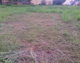
The machine was tested on a grass of mean height of 800 mm, width 20 mm and 16 mm2 demarcated area as shown in Figure 3 (a and b).
Operational time under manual and machine cut were taken with a stop watch.
Machine time spent in cutting under normal working speed condition was subtracted from manual cutting time applicable to standard average human speed.
Productivity increase (%) = ![]() (5)
(5)
|
Figure 3 (a). Uncut grass of mean height 800 mm |
Figure 3 (b). Cut grass of mean height 60 mm |

Results and Discussion
Vibration test results
Vibration velocity amplitude with time for the frame, engine and push handle with and without belt connection are shown in Figures 4 and 5 respectively.
Average velocity amplitudes of frame, engine and push handle when transmission belt is connected were 141.30, 140.95 and 115.50 mm/sec. respectively. The frame vibration is highest because of the combination of cutter and engine seat vibrations that are transmitted to it. Corresponding vibration values when no belt was connected were 27.4, 51.10 and 36.06 mm/sec.
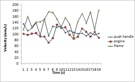
Figure 4. Vibration levels with belt connected
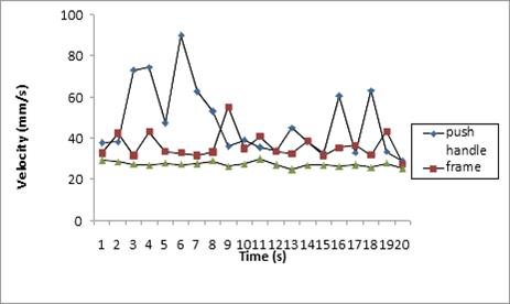
Figure 5. Vibration levels without belt connection
The engine vibration is highest at no load due to its own rotating parts while other sources of vibration such as cutter is nil. A significant increase of vibration obtains when transmission belt was connected due to the effect of high vibration transmission from the cutter to other parts of the mower.
Productivity test results
Machine time spent in cutting was 5.07 minutes under normal working speed condition while manual cut of the same area was 9.03 minutes at average human speed. The mean height of the grass after cut was 60 mm as shown in Figure 3 (b). Productivity increase due to use of machine is 43.84 %.
Noise level test results
The measured noise level reading from different stages of the running machine is presented in Table 2.
Table 2. Noise level of the Lawn Mowing Machine
|
S/N |
Sound before cranking the engine (dB) |
Sound when engine is running and belt engaged (dB) |
Sound when engine is running without belt engaged (dB) |
Sound when engine is running with belt and blade engaged (dB) |
|
1 2 3 4 5 |
52.8 49.6 50.2 49.3 48.9 |
83.4 88.1 87.7 85.2 83.2 |
76.8 77.2 77.8 79.1 75.4 |
92.1 92.1 92.0 92.4 92.3 |
Derived from Table 2 above are the following values:
(i) Average noise level when running the machine with belt engaged = 85.57 dB
(ii) Average noise level when machine is off = 49.1 dB
(iii) Actual noise level of machine with belt engaged = 36.43 dB
(iv) Average noise level without belt engagement = 77.32 dB
(v) Actual noise level of prime mover and mower frame = 28.22 dB
(vi) Actual noise level of gear, pulley and bearings = 8.21 dB
(vii) Average noise level with belt and blade engaged = 92.18 dB
(viii) Actual noise made by blade alone = 6.61 dB
Environmental noise accounted for 49.1 dB. Highest noise level of gross value 92.18 and a net value of 36.43 dB was observed when machine operates with transmission belt engaged. This resulted from a combination of noise from the prime mover, frame, pulleys, bearings, gears and belt. The low noise level of transmission elements which is 8.21 dB is due to effective lubrication of the gears and bearings.
Conclusion
The following conclusions can be drawn from the research:
(a) An orthogonal power transmission weed cutting machine was designed, fabricated and tested. The machine had a productivity increase of 48.85% when compared with manual grass cutting process.
(b) Vibration caused by the machine is high and the machine tends to vibrate higher when the belt is engaged than when disconnected. The machine vibrates highest in the push handle as compared to the engine itself and the frame when belt is not engaged. Highest vibration level of 178.5 mm/s at the handle is below stipulated international standards for vibration in humans (above 200 mm/s for 8 hours exposure is very uncomfortable for human (ISO 2631).
(c) Maximum net sound level of 36.43 dB was produced by the machine (ISO benchmark for safe hearing is 85 dB (ISO 4871)).
Acknowledgement
The authors wish to acknowledge the Department of Mechanical Engineering, University of Ilorin, Nigeria who partly sponsored this research. The technical assistance of Mr. Ologbonsaiye during fabrication and testing is acknowledged and Mr. Dada for carrying out the welding and fittings.
References
1. Okafor B., Simple design of self-powered lawn mower, International Journal of Engineering and Technology, 2013, 3 (10), p. 933-938.
2. Pokhare R., Manually operated lawn mower applicable for grass cutting, International Journal of Scientific Research, 2014, 13 (4), p. 1-15.
3. Nkakini S.O. and Yabefa B.E., Design, fabrication and evaluation of a spiral blade lawn mower, European Int. Journal of Science and Technology, 2014, 3 (4), p. 1–8.
4. Tremonia F., Concerning the sharpness of blades, (available on www.hroar.com...../sharpness.pdf, accessed on 20th March, 2014).
5. Schumacher L., How lawn mower works, (available on: http://home.howstuffworks.com/Lawn-mower.htm (accessed on 18th November, 2015).
6. Mott R.L. Machine elements in mechanical design, 2013, 5th Edition, Pearson.
7. Cleveland V. C., How to fix vibration in a push behind mower, (available at: http://www.ehow.com/how-fix-vibration-push-mower.html, accessed on 18th November, 2015).
8. Alex H., Clark C., Jean-Francois L., Erica M., Design and building of a battery powered electric reel mower, Final design report, Reel Mower Team 15, Department of Mechanical Engineering, Dalhousie University, U.S.A, 2014 (available on http://www.poisson .me.dal.ca/-dp_13_15/the team.html, accessed on 12th,April, 2018).