Engineering, Environment
Novel multilayer composite of conductive fiber for enhancement of the parameters electromagnetic interference shielding
Tahar MERIZGUI 1,2*, Abdechafik HADJADJ 2, Mecheri KIOUS 3, Bachir GAOUI 1
1 Laboratoire des Semi-conducteurs et Matériaux Fonctionnels, Université Amar Telidji de Laghouat, BP 37G, Laghouat 03000, Algeria
2 Laboratoire d’Analyse, de Commande des Systèmes d’Energie et Réseaux électriques, Université Amar Telidji de Laghouat, BP 37G, Laghouat 03000, Algeria
3 Département d'électronique, Université Amar Telidji de Laghouat, BP 37G, Laghouat 03000, Algeria
E-mail(s): t.merizgui@lagh-univ.dz; a.hadjadj@mail.lagh-univ.dz;
m.kious@mail.lagh-univ.dz; b.gaoui@lagh-univ.dz
* Corresponding author, phone: +213 775 424 422
Received: July 28, 2018 / Accepted: October 29, 2018 / Published: December 30, 2018
Abstract
In this work, we propose a new multilayer arrangement structure based on the composite materials in order to improve the shielding efficiency of materials. The structure was built from alternating composite (fiber of copper) embedded dielectric (silicon) layers, this dielectric layers are sandwiched between composite films to get a symmetrical structure that absorbed the electromagnetic waves from its both direction. From the obtained results of reflection, and the total shielding effectiveness mechanisms, the multi-layered proposed in this paper is a better than the monolayer composite in the frequency range from 1 to 10 GHz under the near field regime. The smart stacking of this multilayer structure can improve the shielding effectiveness of materials due to its mismatched impedances (dielectric permittivity, electrical conductivity, and permeability) which increase the multiple reflection mechanism. Another advantages presented by the proposed multi-layered structure are the efficiency and the lightweight that make it an interesting material in shielding applications.
Keywords
Lightweight design; Composite; Electromagnetic interference shielding; Electrical proprieties; Copper fibers
Introduction
Due to mass constraints, multilayer composites are increasingly being used to replace metal alloys in several applications such as operation and control of the commercial electronic equipment and systems [1]. All electric and electronic equipment generate with each other the undesirable electromagnetic fields which is called the electromagnetic interferences (EMIs) which has a harmful impacts on the performance of the devices, human health, and the surrounding environment [2-3].
Recently, Aircraft and spacecraft industries use the composite materials reinforced by metals such as copper and carbon due to its high conductivities, mechanical properties, and the its lightweight that make the composite materials an attractive material especially where the mass of materials should be low as possible. Several strategies proposed by authors [4-9] have obtained a promising results by adding different materials like copper Cu, CuAlMn, CF, MWCNTs, CNT and Fe3O4.
Practical experiences were conducted on these composites that showed their applicability in the most of industries thanks to its advantages that including: (a) providing a feasible way to produce lightweight and multifunctional materials, (b) improving the elastic modulus, damping as well as storage modulus, (c) being simple, low cost, and environmentally-friendly and having potential industrial applications in the future. In fact, composite materials for EMC applications contain conductive inclusions or fibers embedded in a dielectric medium.
The multilayer composites that made up of fiber cross-sections of copper embedded in the matrix (Si) have a lighter weight than the monolayer composite, and their electrical characteristics are relatively similar; these composites are the best candidates for electromagnetic shielding applications due to their efficiency, high flexibility, and low cost [10-12].
The aim of this paper is to treat the problem of mass constraints in electromagnetic compatibility (EMC) and especially of EMI shielding by novel multilayer composites made of copper (Cu) fibres dispersed in silicon matrix (Si).
The comparison between the monolayer composite and our proposed structure which is obtained by placing a dielectric layer between two composite layers prove the efficiency of our multilayer material. The insulating layer (Si) is sandwiched between two composites of (CuF) with the same thickness, resulting in a better electromagnetic shielding performance due to the high conductivity of copper and the multilayer structure which trap the waves inside.
The first mechanism of EMI shielding, reflection (R), depends on the permittivity (ɛ) and electrical conductivity (σ) from the shield slab.
The second mechanism, absorption (A), is based on magnetic permeability of the sample.
The third mechanism, multiple reflections (M), depends on physical properties and the geometric design of the materials. In the first case, we aim at studying the monolayer structure of composite material composed of 58 fibers of (CuF); copper has a high conductivity σ = 5.8*107 S/m, and 0.035 mm radius embedded inside the dielectric layer (Si) a high permittivity ɛ = 11.9 with 0.5 mm thick. Silicon has perfect properties, better chemical stability, high flexibility, and premium corrosion resistance with lighter weight. The traced curves represent the reflection, absorption, multi reflection, and EMI shielding mechanisms. In the second case, we have proposed a novel multi-layer structure which is a two layered composite separated by a dielectric layer (0.25 µm thick) to improve its immunity against the electromagnetic waves.
The structure has the same composite layer as the monolayer structure containing 58 fibers (CuF) with an σ = 5.8*107 S/m, and 0.035 µm radius embedded inside the dielectric layer (Si) a ɛ = 11.9 with 0.5 µm thick. From the presented results in this paper, we can conclude that the proposed multilayer structure CuF/Si–Si–CuF/Si can increase the shielding effectiveness by increasing the reflection and multiple-reflection waves between the layers, and also by giving optimum estimate of absorption mechanism. The obtained results demonstrate the efficiency of our proposed multilayer composite with low weight compared to the monolayer composite.
Material and method
Monolayer composite
The homogenisation method considered in this study is based on the design of a new inclusion, different from the traditional method as in the previous works [13]. The monolayer proposed is composed of 58 fibers of (CuF) with a high conductivity σ = 5.8*107 S/m, at 0.035 mm radius, and volume fraction Vf = 0.31, the dielectric layer (Si), a high permittivity ɛ = 11.9 at 0.5 mm thick, as shown in Figure 1.
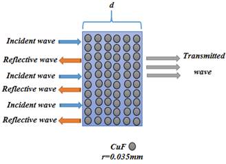
Figure 1. Monolayer structure of composite
The shielding effectiveness of a material is defined by the ratio of the transmitted power (Pt) through the material to the incident power (Pi) of an electromagnetic wave, Eq. [1].
|
SE = -10 log (Pt/Pi)/2 |
(1) |
The sum of absorption and multiple reflection mechanism contributions were calculated by subtracting the reflection from the total shielding effectiveness.
When the shielding slab is illuminated by a perpendicular plane wave, the theoretical model of SE can be expressed as Eq. [2], [13]:
|
SE = SEA+SEM-SER |
(2) |
Where: SEA - the attenuation of the wave caused by the absorption of the material, SEM - the shielding effectiveness by multiple reflection and SER - the shielding effectiveness by reflection.
Also, the shielding effectiveness by absorption which is the first contribution in the total shielding can be expressed as Eq. [3]:
|
SEA = 20 log10 |exp(-jkl)| |
(3) |
Where: ![]() , ɛ and σ -
are the permittivity and conductivity of the material in the direction of the
incident electric field EI and µ - the magnetic permeability in the
direction of the incident magnetic field HI.
, ɛ and σ -
are the permittivity and conductivity of the material in the direction of the
incident electric field EI and µ - the magnetic permeability in the
direction of the incident magnetic field HI.
The second contribution corresponds to reflection, Eq. [4]:
|
SER = 20 log10 |p| |
(4) |
Where: is
the transmission coefficient depending on
is
the transmission coefficient depending on ![]() , the refractive index of the medium.
, the refractive index of the medium.
The third attenuation is caused by multiple reflections inside the material, Eq. [5].
|
SEM = 20 log10 |1-q2*exp(-2jkl)| |
(5) |
Where:  - is the reflection
mechanism.
- is the reflection
mechanism.
So the total resistance of the composite can be obtained as in Eq. [6]:
|
1/RC = 1/Rf1+1/Rf2+…+1/Rf58+1/Rm |
(6) |
When considering the expression ![]() in Eq. [6], we got after some
manipulation, Eq. [7-8]:
in Eq. [6], we got after some
manipulation, Eq. [7-8]:
|
σC= σf ƩAft/AC + σm Am/AC |
(7) |
|
σC= σf Vf+ σm (1-Vf) |
(8) |
In the situation of an insulating matrix, in which 𝜎 ≈ 0, Eq. [9] minimize to:
|
σC ≈ σf * Vf |
(9) |
Where: σc - electrical conductivity of the composite (S/m), σm - electrical conductivity of the matrix (S/m), Vf - volume fraction of the copper fibres, Rm, Rc, Rf - the resistance of the matrix, composite and fiber respectively, A - cross-section area of fuselage skin (m2).
Several researchers [13-14 and 15] indicate that the fiber volume fraction is among the essential parameters in the determination of mechanical properties. So, we want to determine its exact estimate. Mostly, fiber volume fraction is calculated according to ASTM D2584 as Eq. [10], [19-20].
|
Vf = [ρm * ωf / (ρm * ωf + ρf * ωm )] |
(10) |
Where: Vf - volume fraction of fibers, Wf - weight of fibers, Wm - weight of matrix, ρf - density of fibers, ρm - density of matrix.
In this work, we have chosen fibre of copper with length (0.6 mm) and weight (Wf = 0.205 x 10⁻⁶ kg). In addition, the matrix of silicon (a high permittivity ɛ = 11.9) for 0.5 mm thick, at weight (Wm = 0.167 x 10⁻⁴ Kg). The variation in electrical conductivity vs volume fraction as shown in Figure 2.
Figure 2. Variation in electrical conductivity vs volume fraction
The proposed multilayer composite
From the multilayer structure proposed, we have obtained the desired objectives as the results showed a decrease of the absorption mechanism by the increase of the reflection and the multi-reflection mechanism, which means an improvement in the shielding effectiveness with a lightweight.
In this report, we have proposed a new multi-layer structure with two layers (1 and 3) presenting the same characteristics and containing 58 fibres (CuF) with an σ = 5.8*107 S/m, at 0.035 µm radius embedded via a dielectric layer (Si) a ɛ = 11.9 with 0.5 µm thick. The two layers are separated by a dielectric layer (Si) at 0.25 µm thick as shown in Figure 3a.
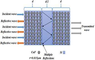
Figure 3a. The proposed multilayer structure CuF/Si–Si–CuF/Si
When the wave reaches the slab we obtain the following reflection, absorption or transmission, S-parameters can be defined as Eq. [11].
|
A = 1- R - T |
(11) |
Where: R and T - are the reflection and transmission power respectively, calculated based on the S parameters; it can be defined from the VNA as follows Eq. [12-13].
|
R = |S11|2 = |S22|2 , R = |S12|2 = |S21|2 |
(12) |
|
S11 = S22 = Γ(1 – T2)/1- Γ2T2 , S21 = S12 = T(1 – Γ 2)/1- Γ2T2 |
(13) |
Where: |Sij|2 - represents the power reflection (i=j) and
transmission (i![]() j)
from port i to port j.
j)
from port i to port j.
Thus, the complex permittivity and the complex permeability can be expressed as Eq. [14-17].
|
μr / εr = (1+Γ/1-Γ) = C1 , μr εr = - {(C/ωt) ln 1/Z }2 = C2 |
(14) |
|
εr2 = C1/C2 , μr2 = C1C2 |
(15) |
|
Γ = Z – Z0/Z + Z0 |
(16) |
|
Z2 = exp(-j2ω2 μ ε d) |
(17) |
Where: d - the thickness of the sample.
Figure 3b shows the procedures selected in calculating the shielding effectiveness.
Figure 3b. Algorithm of methods
Results and discussion
Comparison between monolayer and the proposed multilayer structure composite
Copper (Cu) is a so strong metal with the best properties and has a great potential for much structural, electrical, electronic applications, high conductivity, and low cost. In addition, it is used at a very high rate given its proprieties (low penetration depth and reflection of EM waves) which were considered as an interesting material in the most shielding applications. Metals based on EM absorption are impossible to obtain because the metals serve as mirror due to its conductivity so the EM waves do not penetrate the shield slab, but instead they reflect the waves.
The object of shielding by absorption mechanism is to increase of the multiple reflections within the material. The following simulation results of the reflection, absorption, multi-reflection and the shielding effectiveness have proven the efficiency of the analytical model that has been used in [14-18].
Figures 4, and 5 display the EMI reflection, and shielding effectiveness mechanisms of the multilayer structure (CuF/Si-Si) and the monolayer composite (CuF/Si). Moreover, the multilayer proposed in this paper is composed of two reflective composite layers separated by a dielectric layer (CuF/Si-Si).
Figure 4. Reflection mechanism of a composite material
Figure 4 presents the reflection loss in the frequency range 1 to 10 GHz. Through these results, we noticed a clear difference: the proposed multilayer composite has a better performance compared to the monolayer composite material.
The results showed varying values in favour of the multilayer material, good performance and an impedance disparity between the dielectric layer and conductive fibre (CuF). At the same time, the presence of multi-reflection increases the total reflection inside the composite material; this is mainly due to the multi-reflection between the dielectrics layers due to the high mismatched impedances.
Figure 5 displays the variation of EMI shielding effectiveness versus frequency; the proposed multilayer composite presents a best attenuation of EMI SE.
Figure 5. Shielding effectiveness of a composite material
As the wave progresses in the multilayer composite material, reflection rises but it occupies the place inside the composite material.
The results presented here prove also the enhancement of the EMI shielding effectiveness. For the mass problem, we have chosen the multilayer composite (CuF) separated by dielectric layer because its low weight.
Due to the increase of impedance in the multi-reflection mechanism, the reflection loss increases in all the frequency range 1– 10 GHz.
The electromagnetic parameter analysis of the proposed multi-layer composites
The electromagnetic property of CuF/Si multi-layer composite is resolved by complex permittivity (ε= ε'- jε"), permeability (μ = μ'- jμ"), and impedance (z = z' - jz'') [10].
The real part of the electromagnetic key parameters (ε', μ') is a measure of the amount of polarization taking place in the proposed material and show the ability for magnetic or electric power storage, while the imaginary part (ε", μ") represents the power loss.
The real part ɛ' and imaginary part ɛ'' of the proposed multi-layer as shown in Figure 6 at frequencies between 1–10 GHz. As displayed in Figure 6, the real part of the permittivity gradually decreases with increased frequency and takes the values from 5.67 at 1 GHz, and 5.35 at 10 GHz.
Figure 6. Real and imaginary parts of permittivity (ɛ) of the analysed multi-layer proposed
These results from Figure 6 indicate that the electric power storage capability of multilayer composites has a better performance.
The imaginary part of the permittivity increases with increased frequency; this evolution is estimated from 0.25 at 1 GHz, and 1.29 at 10 GHz. The result obtained supports the amelioration of the EMI SE.
The real part µ' and imaginary part µ'' of the proposed multi-layer as shown in Figure 7, when frequency increases from 1 GHz to 10 GHz.
Figure 7. Real and imaginary parts of permeability (µ) of the analysed multi-layer proposed
As shown in Figure 7, the real part of the permeability is relatively increasing with the frequency and changes from 0.5022 at 1 GHz, to peak at 0.505 at 10 GHz.
The imaginary part of the permeability decreases gradually by increased frequency; so, the value changes from 0.5032 at 1 GHz, and 0.5028 at 10 GHz. The result obtained supports the improvement of the EMI SE by less absorption mechanism.
The real part z' and imaginary part z'' of the proposed multi-layer as shown in Figure 8, when frequency increases from 1 GHz to 10 GHz.
As shown in Figure 8, the real part of the impedance is relatively increasing (z'>0) with increased frequency and changes from 2.08 at 1 GHz, to peak at 34.83 Ω at 9.2 GHz, to return to the same value with the first value 2.08 Ω at 10 GHz.
Figure 8. Real and imaginary parts of impedance (z) of the analysed multi-layer proposed
The imaginary part of the impedance changes relatively (Figure 8) so that it takes both positive and negative values with increased frequency, from -1.316 Ω at 1GHz, 23.18 Ω at 9.2GHz, and 0.3 at 9.2GHz. The result obtained supports the improvement of the EMI SE by the multi-reflection mechanism.
Conclusions
A new multilayer material built from alternating composite of (CuF) and dielectric layers of silicon (Si) shows a great performance of shielding effectiveness by less outside reflection. The absorption mechanism contribution and the symmetrical structures of the composite give a perfect protection of the electronic devices.
Major studies demonstrated that the effectiveness of the proposed multilayer composite regarding electromagnetic waves is clear, thanks to its elevated conductivity, thus a great reflection mechanism, and an increasing value of multiple internal reflection waves between the composite layers which serve as a snare that traps the wave within the stacked composite arrangement with less outside reflections.
Also, the proposed structure has the advantage of being a high efficiency, lightweight and low cost compared to the monolayer composite.
References
1. Gnidakouong J.R.N., Kim M., Park H.W., Park Y.B., Jeong H.S., Jung Y.B., Ahn S.K., Han K., and Park J.M., Electromagnetic interference shielding of composites consisting of a polyester matrix and carbon nanotube-coated fiber reinforcement, Composites Part A: Applied Science and Manufacturing, 2013, 50, p. 73–80.
2. Kwon S. and Lee H.K., A computational approach to investigate electromagnetic shielding effectiveness of steel fiber-reinforced mortar, Computers, Materials & Continua (CMC), 2009, 12 (3), p. 197.
3. Gaoui B., Hadjadj A., and Kious M., Novel multilayer arrangement of conductive layers traps the electromagnetic interferences by multiple internal reflections at high frequency in the far field, Journal of Materials Science: Materials in Electronics, 2017, 28 (4), p. 3924–3930.
4. Ji X., Wang Q., Yin F., Cui C., Ji P., and Hao G., Fabrication and properties of novel porous cualmn shape memory alloys and polymer/cualmn composites, Composites Part A: Applied Science and Manufacturing, 2018, 107, p. 21–30.
5. Chen J., Wu J., Ge H., Zhao D., Liu C., and Hong X., Reduced graphene oxide deposited carbon fiber reinforced polymer composites for electromagnetic interference shielding, Composites Part A: Applied Science and Manufacturing, 2016, 82, p. 141–150.
6. Wang H., Zheng K., Zhang X., Du T., Xiao C., Ding X., Bao C., Chen L., and Tian X., Segregated poly (vinylidene fluoride)/mwcnts composites for high-performance electromagnetic interference shielding, Composites Part A: Applied Science and Manufacturing, 2016, 90, p. 606–613.
7. Nam I., Lee H.K., and Jang J., Electromagnetic interference shielding/absorbing characteristics of cnt-embedded epoxy composites, Composites Part A: Applied Science and Manufacturing, 2011, 42 (9), p. 1110–1118.
8. Sudha J., Sivakala S., Patel K., and Nair P. R., Development of electromagnetic shielding materials from the conductive blends of polystyrene polyaniline-clay nanocomposite, Composites Part A: Applied Science and Manufacturing, 2010, 41 (11), p. 1647–1652.
9. Zhang H., Zhang G., Li J., Fan X., Jing Z., Li J., and Shi X., Lightweight, multifunctional microcellular pmma/fe3o4@ mwcnts nanocomposite foams with efficient electromagnetic interference shielding, Composites Part A: Applied Science and Manufacturing, 2017, 100, p. 128–138.
10. Wong K., Pickering S., and Rudd C., Recycled carbon fibre reinforced polymer composite for electromagnetic interference shielding, Composites Part A: Applied Science and Manufacturing, 2010, 41 (6), p. 693–702.
11. Sharma S., Singh B.P., Chauhan S.S., Jyoti J., Arya A.K., Dhakate S., Kumar V., and Yokozeki T., Enhanced thermomechanical and electrical properties of multiwall carbon nanotube paper reinforced epoxy laminar composites, Composites Part A: Applied Science and Manufacturing, 2018, 104, p. 129–138.
12. Yang S., Lozano K., Lomeli A., Foltz H.D., and Jones R., Electromagnetic interference shielding effectiveness of carbon nanofiber/lcp composites, Composites Part A: applied science and manufacturing, 2005, 36 (5), p. 691–697.
13. Préault V., Corcolle R., Daniel L., and Pichon L., Influence of skin effect on the effective shielding effectiveness of composite materials, Journal of Applied Physics, 2014, 115 (15), p. 154904.
14. Karteri I., Altun M., and Gunes M., Electromagnetic interference shielding performance and electromagnetic properties of wood-plastic nanocomposite with graphene Nano platelets, Journal of Materials Science: Materials in Electronics, 2017, 28 (9), p. 6704–6711.
15. Nedjem Z., Seghier T., and Hadjadj A., New multilayer arrangement of dielectric layers for enhancement of the magnetic shielding absorption at low frequency in the near field, Journal of Materials Science: Materials in Electronics, 2016, 27 (4), p. 3202–3208.
16. Liu L., Bian X.M., Hou Z.L., Wang C.Y., Li Z.S., Hu H.D., Qi X., and Zhang X., Electromagnetic response of magnetic graphene hybrid fillers and their evolutionary behaviours, Journal of Materials Science: Materials in Electronics, 2016, 27 (3), p. 2760–2772.
17. Saboor A., Khan A.N., Cheema H.M., Yaqoob K., and Shafqat A., Effect of polyaniline on the dielectric and emi shielding behaviours of styrene acrylonitrile, Journal of Materials Science: Materials in Electronics, 2016, 27 (9), p. 9634–9641.
18. Gaoui B., Hadjadj A., and Kious M., Enhancement of the shielding effectiveness of multilayer materials by gradient thickness in the stacked layers, Journal of Materials Science: Materials in Electronics, 2017, 28 (15), p. 11292–11299.
19. Pan N., Theoretical determination of the optimal fiber volume fraction and fiber-matrix property compatibility of short fiber composites, Polymer composites, 1993, 14 (2), p. 85–93.
20. Batch G.L., Cumiskey S., Macosko C.W., Compaction of fiber reinforcements, Polymer composites, 2002, 23 (3), p. 307–318.