Engineering, Environment
Static stress analysis and displacement of a tricycle rear shock absorber using finite element analysis
Temitope Olumide OLUGBADE 1*, Tiamiyu Ishola MOHAMMED 2, Oluwole Timothy OJO1
1 Department of Industrial and Production Engineering, Federal University of Technology, PMB 704, Akure, Ondo State, Nigeria
2Department of Mechanical Engineering, Federal University of Technology, PMB 704, Akure, Ondo State, Nigeria
E-mails: tkolugbade@futa.edu.ng1*, timohammed@futa.edu.ng2, otojo@futa.edu.ng1
*Corresponding Author, Phone: +2348068859326
Received: August 14, 2018 / Accepted: November 19, 2018 / Published: December 30, 2018
Abstract
The static stress analysis and displacement of a tricycle rear shock absorber using finite element analysis (FEA) were carried out. The design of spring in the suspension system was also studied. A physical model (pressure model and flow model) was adopted and implemented for the modelling of the tricycle shock absorber. The pressure model determines the internal pressures while flow model calculates the oil flow between the tricycle chambers. Static stress analysis and displacements were performed by varying materials for suspension spring and considering the tricycle weight at a loading capacity of 1500 kg as well as when the loading capacity was exceeded by 200 kg. The analysis was done to validate the strength and determine the best spring material for this application. A comparison was made between the existing spring material Model and other available spring materials. The results showed that the spring made of Inconel X-750 has the least stress value when compared to other spring materials. This makes it a better material in terms of load bearing capability. However, the material retained its position as the most considerable material for making springs when the loading capacity of the tricycle was exceeded and when there is unexpected overloading.
Keywords
Static stress analysis; Finite element analysis; Shock absorber; Tricycle
Introduction
In vehicle dynamics, shock absorbers are part of the suspension system and the importance of suspension cannot be overemphasized. It is needed to guarantee good handling, braking, and comfort. Due to its complexity, it is sometimes challenging to design and model a shock absorber of a suspension. It is therefore important to consider some factors while designing for shock absorber, which includes geometry, strength, durability, and functionality. A shock absorber is a mechanical assembly which is majorly used to support the weight, absorb road shock and maintain tire contact as well as the proper wheel to chassis relationship in automotive industries and structure analysis [1-2]. It does not only smooth out or damp shock impulse but also absorb and dissipate the impact kinetic energy in such a way that accelerations imposed upon the airframe are reduced to a tolerable rate [3]. Major problems associated with tricycle operation are low ride quality, discomfort when over rough ground and unnecessary disturbances. Also, the spring is compressed too quickly most times when a tricycle is traveling on a level road and the wheels strike a bump. These problems can be resolved by designing a good shock absorber for the tricycle using finite element analysis (FEA). This was accomplished by designing a shock absorber using FEA which will, in turn, control the spring and suspension movement.
Nowadays, several methods are available to model suspension system in a tricycle. The applicability of these methods, discrete or diffuse depends on how they account for the supposed discontinuity. To model a shock absorber, node splitting, cohesive surfaces, hybrid discrete and finite element analysis are the common techniques using discrete methods [4-8]. Finite element analysis (FEA) has been considered as an effective tool in shock absorber design to reduce the error caused by the simplification of equations [9]. It has been presented to solve many problems and equations numerically, for examples, modelling for chloride binding in mesoscale concrete [10], phase-field solution for modelling brittle fracture [11], dynamics of flexible beams [12], modelling hybrid all terrain trike [13], solid-shell formulation [14], determining the reference geometry [15] and modelling helical compression spring for vehicle automotive front suspension [16].
Recently, studies on shock absorber and the suspension system have been a subject of investigation. It has been established that without suspension, the tires could lose contact with the road, traction would be lost, the ride would be uncomfortable, and chassis would as well be subjected to damaging shock loads (9, 17-19). Finite element analysis (FEA) tools and analytical solutions were used to compare the different stress and deflection values in shock absorber components. Świtoński et al. [20] studied and analysed stiffness and damping of shock absorber system. The results emphasized that the stiffness and damping value for shock absorber is strongly related to the capacity of the shock absorber that was considered. Some other factors such as damping force, control energy, and time constant are also important when designing for shock absorber [21-23]. These factors and others like material selection and strength, impact energy, toughness and durability are essential when designing for engineering components [36-42].
Despite the various work done, few or little work has been done on the static stress analysis and displacement of suspension spring of a tricycle. The comparison of different spring materials that can be used for the design and analysis of the suspension spring of a tricycle has also not been properly investigated.
In the present work, static stress analysis and displacement of a tricycle rear shock absorber using finite element analysis (FEA) was carried out by varying coil springs made of different materials. Firstly, a shock absorber used in the rear of a tricycle was designed and a 3D model was created. In addition, a comparison was made between the current spring material (Monel K-500) and four other common spring materials to determine the best for making suspension springs in tricycle shock absorber. The physical damper model is adopted for the pressure model and flow model of the tricycle.
Materials and methods
Design calculations for the suspension spring shock absorber
The suspension spring shock absorber comprises of coil spring (helical), damper, piston and fluid (oil). The analytical calculation for the considered suspension assembly was performed using the basic design calculations and the same was compared with the ANSYS results. Figure 1 illustrates the working algorithms of the designed tricycle rear shock absorber.
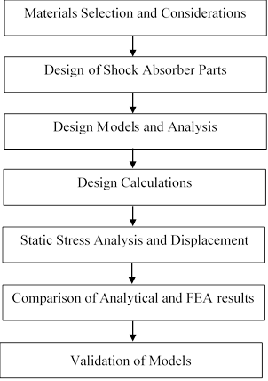
Figure 1. Working algorithm of the designed tricycle rear shock absorber.
In Figure 1, the working algorithm of the designed tricycle rear shock absorber include the materials selections, design of shock absorber parts, design models, analysis and calculations, and validation of models. The design of the coil-over helical spring was done using the following vehicle data and information. Wet weight of tricycle (W) is 1200 kg (weight include oil, fuel etc.). Loading capacity of tricycle is 1500 kg (weight includes added masses such as persons). The rear axle bears the 63% of total weight (i.e.945 kg with load and 756 kg without load) while front axle bears the remaining 37%.
Using the above vehicle data, the force on rear axle
with and without load was obtained to be 9450N and 7560 N respectively. The
tricycle has two rear shock absorbers. With load, the force exerted on each
rear shock absorber was 4725 N while it was 3870 N without load. The vertical force (with
load) was 4725 N and the vertical displacement of the tire ground contact with
respect to chassis (with load) was 220 mm. By calculation, the ride rate of the
tricycle with load (vertical force per unit vertical displacement of the tire
ground contact with respect to chassis) was obtained to be![]() .
The ride rate of the tricycle with and without load are 21.47 Hz and
.
The ride rate of the tricycle with and without load are 21.47 Hz and ![]() respectively
and the difference in the ride rate with and without load is 4.29 Hz. This
implies that the rate at which tricycle operates and moves (when fully loaded)
is more convenient and comfortable to users compared to the tricycle without
load, which agrees with the previous findings [19, 24-25].
respectively
and the difference in the ride rate with and without load is 4.29 Hz. This
implies that the rate at which tricycle operates and moves (when fully loaded)
is more convenient and comfortable to users compared to the tricycle without
load, which agrees with the previous findings [19, 24-25].
Design considerations for the suspension spring (Helical)
In the present study, proper design of compression springs was taken into consideration which requires the knowledge of both the potential and the limitations of available materials together with simple formulae. The design of a coil spring involves the following basic considerations: space into which the spring must fit and operate, working forces and deflections, accuracy, reliability, tolerances, ride height, environmental conditions such as temperature, cost and quality. These factors were used to select a material and suitable values for the wire size, the number of turns, the coil diameter and the free length, type of ends and the spring rate which is needed to meet the working force deflection requirements. The primary design constraints are that the wire size should be commercially available and that the stress at the solid length be no longer greater than the torsional yield strength.
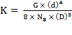
The spring rate was calculated using the primary features which include the inside diameter, wire diameter, coil mean diameter and number of active coils. The implication of spring rate is that the greater the rate, the stiffer the spring and the more pounds of load it takes to compress the spring one inch, Eq. [1], [17].
 (1)
(1)
Where: K - spring rate, G - modulus of rigidity, d - wire diameter, D - coil mean diameter, Na - number of active coils.
Evident from Eq. (1), suspension spring dimension including the wire diameter, mean coil diameter, and the number of active coils is the major factors affecting the spring rate of a steel coil. In the design analysis, value for modulus of rigidity was 2.124E+5 MPa, mean diameter of a coil (D) was 80 mm, total no of coils (C) was 10, height (h) was 220 mm, diameter of the wire (d) was 10 mm and the outer diameter of spring coil (D) was 90 mm, which was obtained by the addition of inner and outer diameter of the spring coil. The axial load exerted on the spring using the data in the design analysis was obtained to be 4725 N. The model of the shock absorber assembly comprises the bottom part, top part and coil spring.
The physical damper model for the tricycle
The physical damper model adopted [26] was used for the modelling and analysis of the tricycle rear shock absorber. The damper model was split into pressure model and flow model. The pressure model predicts the internal chamber pressures while the flow model determines the oil flow (Q) between the chambers in function of the pressure drop ∆p through a set of static equations. From the rebound and compression chamber pressures, friction and bumper force, the damper force is obtained, Eq. [2].
![]() (2)
(2)
Where: F- damper force, Apt – area of pressure tube, Arod – area of damper rod, Preb – rebound pressure, Pcom – compression chamber pressure, Fbumper - bumber force
Pressure model
Through a set of differential equations, the pressure model determines the dynamic features of the damper. At low frequencies, the set of differential equations are related to the adiabatic compression of the gas present in the reserve tube. It is important to note that some undesirable effects such as the mixture of gas and oil in the pressure tube [27] can directly affect the value of the bulk compressibility. The presence of such effects can greatly affect the damper efficiency due to low bulk modulus. Double-tube and mono-tube design are considered under the pressure model. This is because the difference in modelling of both types is most relevant to pressure model. For double-tube design, the set of differential equations which can predict the built-up of pressure in the pressure tube are presented in Eq. [3-4].
![]() (3)
(3)
![]() (4)
(4)
Where: Ṗreb – rebound pressure (differentiation), Ṗcom – compression pressure (differentiation), Qpv – flow rate of piston valve, Lpt – length of pressure tube, α – compressibility (Pa-1), x - displacement (m), ẋ - differentiation of x, x0 – initial displacement, bv – base valve, pv – piston valve
For the reserve tube, the compressibility of the oil is infinitesimal compared to the present gas. Hence, the reserve tube can be predicted from a polytrophic compression or expansion, during the compression and rebound stroke, Eq. [5].
![]() (5)
(5)
Where: Prt - pressure of
reserve tube, Prt.0 - pressure of reserve tube, at original point, Vrt.gas.0
–volume of reserve tube, gas at original point, x-displacement (m),![]() -
polytropic exponent.
-
polytropic exponent.
For mono-tube design, only one tube is present and the change of volume inside the damper body is compensated by a volume of gas at high pressure. In the rebound chamber, the pressure remains the same while the pressure in the compression chamber is determined by the compressed gas, Eq. [6-7].
![]() (6)
(6)
![]() (7)
(7)
Where: Pcom.0 – compression pressure, at original point, Vcom.gas.0 – compression volume, at original point.
Flow model
The flow model shows the relationship between the flow rates through the valve assemblies and the pressure drops. Pressure flow and intake flow are the two major models under flow model. The pressure flow is responsible for the build-up of pressure drop across the piston while the intake flow does not build up any important pressure drop across the valve assembly, Eq. [8].
![]() (8)
(8)
Where: Δp -pressure drop, Bi – global restriction coefficient, Qri – flow rate restriction coefficient.
The series is truncated at two terms (m=2) with r1 = 1 and r2 mostly lies between 1 and 2. From literatures [28-29] r2 is usually fixed as 2 and calculate the coefficient B2, Eq. [9].
![]() (9)
(9)
Where: B2 - coefficient, ρ – oil density (kg/m3), CD – discharge coefficient, AV – valve area.
The discharge of coefficient CD is usually a function of the Reynolds number, the Cauchy number, the acceleration number and the thickness to length ratio of the restriction [17]. Using B2 = 1.75, Reybrouck [30] argues that, Eq. [10].
![]() (10)
(10)
Where: Kleak – orifice stiffness, V1/4 – volume (m3), Qleak7/4 – orifice flow rate.
Considering the blow-off condition, Eq. [11].
![]() (11)
(11)
Where: ΔPblow-off – blow-off pressure drop, ΔP0 – specific pressure developed
Blow-off valve can be modelled using Eq. [12]:
![]() (12)
(12)
Where: Kspring – stiffness of blow-off spring, Qblow-off – blow-off flow rate
Based on literatures [17, 29, 31-33], Kspring and ∆Po can be obtained with Eq. [13, 14].
![]() (13)
(13)
![]() (14)
(14)
Where: CD – discharge coefficient, П – constant (3.142), dv – valve diameter, Av – valve area
The total valve feature is determined by taking into consideration, Eq. (15-17).
![]() (15)
(15)
![]() (16)
(16)
![]() (17)
(17)
Where: ΔPtotal – total pressure drop, ΔPport – pressure drop in port channel, ΔPparallel – pressure drop in parallel, ΔPleak – pressure drop in orifice, Qtot - total flow rate, Qleak - orifice flow rate, Qblow-off - blow off flow rate.
In series, the pressure drop across two elements is the addition of the pressure drop across each element (Eq. [15]). The pressure drop in parallel, across two elements is the same to the drops across each element (Eq. (16)) while the total flow of two valves in parallel is equal to the sum of the flows across individual elements (Eq. (17)).
Finite element approach (FEA)
The model was validated by comparing with the results obtained from Pinjarla and Lakshmana [3] and Sudarshan et. al [19]. The parameters used for the validation (compares between the developed model and the published results) are the loading capacity, force exerted, analytical stress, boundary conditions and material properties. The percentage error between the analytical stress obtained from this work compared with the previous result [3, 19] is 2.11 % while the percentage error in terms of loading capacity is 1.98 %, which is similar with the previous work [19, 24]. FEA was used to predict the behaviour of a model in response to loads that it will be subjected to. FEA allows for model development to be carried out at low cost and can result in the removal unnecessary mass should it be determined that the design would still retain enough strength properties without it.
Results and Discussion
Static stress analysis and displacement of selected wire materials
The analytical and FEA results obtained from the static stress analysis and displacements of selected shock absorber wire material are presented in Tables 1-4.
Table 1. Static stress analysis and displacements of selected shock absorber wire material
|
No |
Material |
Young’s modulus (E) MPa |
Density (Kg/m3) |
Force (N) |
|
1 |
Nickel Base Alloy (Monel K500) |
1.79×10⁹ |
8440 |
4725 |
|
2 |
High-carbon Steel (ASTM A 228) |
2.1×10⁹ |
7850 |
4725 |
|
3 |
Alloy steel (ASTM A401) |
2×10⁹ |
7850 |
4725 |
|
4 |
Stainless Steel (AISI 302/304) |
1.93×10⁹ |
7860 |
4725 |
|
5 |
High temperature alloy (Inconel X-750) |
2.124×10⁹ |
8280 |
4725 |
Table 2. Summary of FEA result at tricycle loading capacity (4725N) for different shock absorber wire materials
|
No |
Wire material |
Minimum deflection (mm) |
Maximum deflection (mm) |
Maximum stress (MPa) |
Density (Kg/m3) |
|
1 |
Monel K500 |
0.0064707 |
0.010246 |
37.213 |
8440 |
|
2 |
ASTM A 228 |
0.0066108 |
0.010461 |
37.761 |
7850 |
|
3 |
ASTM A401 |
0.0067469 |
0.010678 |
38.534 |
7850 |
|
4 |
AISI 302/304 |
0.0068492 |
0.010841 |
39.130 |
7860 |
|
5 |
Inconel X-750 |
0.0064742 |
0.010244 |
36.978 |
8280 |
Table 3. Summary of FEA result at tricycle overloaded capacity (5000N)
|
No |
Wire material |
Minimum deflection (mm) |
Maximum deflection (mm) |
Maximum stress (MPa) |
Density (Kg/m3) |
|
1 |
Monel K500 |
0.008932 |
0.013518 |
43.434 |
8440 |
|
2 |
ASTM A 228 |
0.009174 |
0.013761 |
44.217 |
7850 |
|
3 |
ASTM A401 |
0.009337 |
0.014006 |
45.000 |
7850 |
|
4 |
AISI 302/304 |
0.009499 |
0.014250 |
45.782 |
7860 |
|
5 |
Inconel X-750 |
0.009012 |
0.013498 |
43.043 |
8280 |
Table 4. Comparison of numerical (FEA) and theoretical values of maximum deflection (loading capacity of 4725N)
|
No |
Method loading (4725 N) |
Monel K500 |
ASTM A228 |
ASTM A401 |
AISI 302/304 |
Inconel X-750 |
|
1 |
Numerical (FEA) |
0.010246 |
0.010461 |
0.010678 |
0.010841 |
0.010244 |
|
2 |
Theoretical |
0.015394 |
0.013122 |
0.013778 |
0.014277 |
0.012973 |
|
Loading (5000 N) |
|
|
|
|
|
|
|
1 |
Numerical (FEA) |
0.013518 |
0.013761 |
0.014006 |
0.014250 |
0.013498 |
|
2 |
Theoretical |
0.0162905 |
0.013885 |
0.014579 |
0.015108 |
0.013728 |
As shown in Tables 1-4, the selected shock absorber wire materials are nickel base alloy (Monel K500), high-carbon steel (ASTM A228), alloy steel (ASTM A401), stainless steel (AISI 302/304) and high temperature alloy (Inconel X-750) (Table 1). The different stress and deflection values in shock absorber wire material was obtained using ANSYS FEA tool. The results obtained at loading capacity (4725 N) for different shock absorber wire materials are summarized in the Table 2. The results obtained when the loading capacity was exceeded for different shock absorber wire materials were also summarized in Table 3. The absorber geometries such as the thickness of spring have influence on the deflection in stiffness and damping of shock absorber system. In addition, the stiffness and damping value for shock absorber are strongly related to the capacity of the shock absorber. The geometric study was considered putting into consideration the damping force, control energy and time constant.
Moreover, Table 4 shows the results obtained when the loading capacity of the tricycle was exceeded. This is required for load bearing structural members to determine their behaviour when there is unexpected overloading. From the results obtained, Inconel X-750 retained its position as the most considerable material for making springs.
|
(a) |
(b) |
(c) |
||
(d) |
(e) |
(f) |
||
|
(g) |
(h) |
(i) |
||
|
(j) |
||||
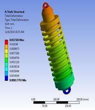
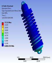
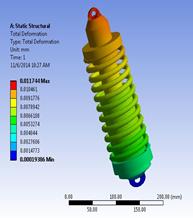
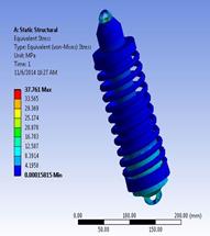
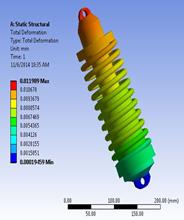
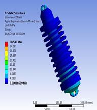

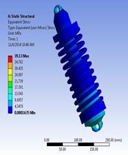
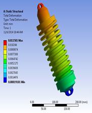
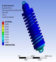
Figure 2. The magnitude of maximum deflection in the spring and the equivalent stress in the shock absorber (a) and (b) nickel base alloy (Monel K500), (c) and (d) high carbon steel (ASTM A228), (e) and (f) alloy steel ASTM A401, (g) and (h) stainless steel (AISI 302/304), (i) and (j) high temperature alloy (Inconel X-750).
Figure 2 a-j shows the magnitude of maximum deflection in the spring and the equivalent stress in the shock absorber of the five (5) selected shock absorber wire materials. For nickel base alloy (Monel K500), the magnitude of maximum deflection in the spring is 0.010246 mm, as shown in Figure 2a and the maximum shear stress in the shock absorber is 37.213MPa, as shown in Figure 2b. Also, from Figure 2b, the values of deflection in Monel K-500 wire under static load of 4725 N force are obtained within the range of 0.0064707 mm and 0.010246 mm.
The magnitude of maximum deformation in the spring for high carbon steel (ASTM A228) is as shown in Figure 2c while Figure 2d shows the maximum shear stress in the shock absorber. The magnitude of maximum deformation in the spring is 0.010461 mm and the maximum shear stress in the shock absorber is 37.761 MPa. Within the range of 0.0066108 mm and 0.010461 mm, from Figure 2d, the values of deflection in ASTM A228 wire under static load of 4725 N force are obtained within the range of 0.0066108 mm and 0.010461 mm. Figure 2e shows the magnitude of maximum deformation in the spring for alloy steel ASTM A401. Figure 2f shows the maximum shear stress in the shock absorber. The magnitude of maximum deformation in the spring is 0.010678 mm and the maximum shear stress in the shock absorber is 38.534 MPa. In Figure 2f, the values of deformation in ASTM A401 wire under static load of 4725N force are obtained within the range of 0.0067469 mm and 0.010678 mm.
In Figure 2g, the magnitude of maximum deformation in the spring for stainless steel (AISI 302/304) is illustrated. Figure 2h shows the maximum shear stress in the shock absorber. The magnitude of maximum deformation in the spring is obtained to be 0.010841 mm and the maximum shear stress in the shock absorber is given as 39.13 Mpa. Figure 2h also showed that the values of deformation in AISI 302/304 wire under static load of 4725 N force are obtained within the range of 0.0068492 and 0.010841 mm. The magnitude of maximum deformation in the spring for high temperature alloy (Inconel X-750) is illustrated in Figure 2i while Figure 2j shows the maximum shear stress in the shock absorber. The magnitude of maximum deformation in the spring is 0.0064742 mm and the maximum shear stress in the shock absorber is 36.978 MPa. The values of deformation in Inconel X-750 wire under static load of 4725N force are obtained within the range of 0.0064742 mm and 0.010244 mm, as evident in Figure 2j.
From Table 3, it can be deduced that the shock absorber made of spring material Inconel X-750 has the least stress value of 36.978 MPa which makes it a better material in terms of load bearing capability, which agrees with the previous results [25, 34]. In terms of deflection or deformation, Monel K-500 has the least deformation with value of 0.0064707mm. This compared with deformation in Inconel X-750 with value of 0.0064742mm is very insignificant and not noticeable. Though, materials with larger deflection value has tendency to buckle than materials with less deflection value, but Inconel X-750 has less deflection value compared to the rest of the materials, as established from previous studies [35].
Weight is also an important aspect of the product development, and every attempt must be made to adhere to the specified weight of the shock absorber. The springs of the various materials are of equal volume with different densities. Inconel X-750 has a density which is lesser than that of Monel K-500 translating to the fact that it is lighter. Compared with the previous reports [17, 28], the shock absorber design is safe because the equivalent stress obtained with the entire materials is lesser than their respective yield strength. Inconel Alloy has higher resistance to deformation and failure because it has the least stress value than Monel K-500; hence, it can be used as an alternative material for making helical springs in tricycle shock absorber, similar conclusion was made [24-25].
Analytical approach
To validate the above result, theoretical calculation is being carried out below for Monel K500, ASTM A 228, ASTM A401, AISI 302/304, Inconel X-750. Consequently, for all the spring materials, the spring constant, maximum deflection (for loading capacity of 4725 N and overloaded capacity 5000 N), spring index and maximum shear stress are calculated using Eq. (18-22):
![]() (18)
(18)
![]() (19)
(19)
![]() (20)
(20)
![]() (21)
(21)
![]() (22)
(22)
Where: G - modulus of rigidity, d - wire diameter, D - mean coil diameter, n - no of
active coils, δ - maximum deflection, F - maximum force, k – spring
constant, C - spring index, ![]() -
maximum shear stress, W - wahl
correction factor.
-
maximum shear stress, W - wahl
correction factor.
The maximum deflection and stress values obtained from the analytical approach are summarized and compared with the numerical values as shown in Table 4.
Comparison of numerical (FEA) and theoretical values of maximum deflection
Figure 3 represents the numerical results of maximum deflection at loading capacity of 4725 N and overloaded capacity of 5000N for different suspension spring materials while the maximum shear stress numerical results for various spring materials at different loading capacity are shown in Figure 4.
|
Figure 3. ANSYS results of maximum deflection at loading capacity of 4725 N and overloaded capacity of 5000 N for different suspension spring materials |
Figure 4. ANSYS results of maximum stress for different suspension spring materials at loading capacity of 4725 N and overloaded capacity of 5000 N |
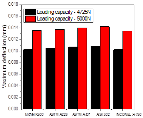
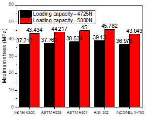
In both the numerical and theoretical analysis, AISI302/304 (among the suspension spring materials) has the highest maximum deflection and stress at loading capacity of 4725 N and 5000 N. At 4725 N, the maximum deflection for numerical and theoretical analysis are 0.010841 mm and 0.014277 mm respectively (Figure 3) while it is 0.014250 mm and 0.015108 mm for numerical and theoretical analysis respectively, at 5000 N (Figure 4).
|
Figure 5. Comparison of numerical (FEA) and theoretical values of maximum deflection for different suspension spring materials at loading capacity of 4725 N |
Figure 6. Comparison of numerical (FEA) and theoretical values of maximum deflection for different suspension spring materials at loading capacity of 5000N |
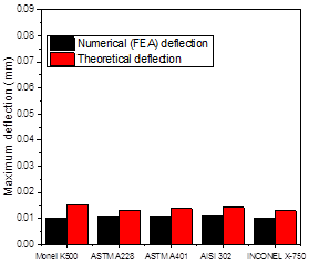
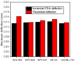
The results obtained from numerical (FEA) and theoretical analysis or both maximum deflection and maximum shear stress are compared, as shown in Figure 5 and Figure 6. The comparison was done when the loading capacity is 4725 N and when there is overloaded capacity (5000N) for the different suspension spring materials.
As evident in Figure 5 and Figure 6, for all the suspension spring materials except Monel K500, it is observed that the numerical and theoretical values for both maximum deflection and shear stress are close when the loading capacity is 4725 N and 5000 N. The significant difference between the numerical and theoretical values of Monel K500 is a little bit more compared to the differential values of the remaining four (4) suspension spring materials.
Conclusions
Statistical stress analysis of suspension spring of a tricycle was carried out to solve the major problems associated with tricycle operation which include low ride quality, discomfort when over rough ground, unnecessary disturbances and quick compression of springs. This was done by designing a good shock absorber for the tricycle using finite element analysis (FEA), which in turn control the spring and suspension movement. The essential points of this work are as follows:
(1) The physical damper model which consist of pressure model and flow model, was adopted for modelling the tricycle, to determine the internal pressure and calculate the oil flow between the tricycle chambers. Static stress analysis of five (5) different suspension spring materials was done. Two different analysis methods are implemented: the numerical analysis using finite element method and theoretical analysis which was employed for validation purpose.
(2) The analysed stress values are less than their respective yield stress values. This makes the design distinct. By comparing the results for the five (5) materials, the spring made of Inconel X-750 has the least stress value, deformation and a density of 8280 kg/m3 which is lesser than that of Monel K-500. It can be concluded that Inconel X-750 is the best material for making helical springs in a tricycle rear shock absorber because of its low deformation value, less weight and cost. This conclusion was confirmed in line with the computations for numerical examples that were studied using the developed model.
(3) The method of finite element analysis was employed to evaluate the performance of different coil spring materials, to determine the material with the least deformation under a given condition (loading).
In future work, the combination of experimental, numerical and theoretical approach will be adopted for the structural and modal analysis of shock absorber. In addition, finite-element formulation based on interpolation of strain measures will be developed and dynamics of flexible spring following the same approach.
Acknowledgements
Special thanks to Fashade Olalekan for his assistance during this research. This research did not receive any specific grant from funding agencies in the public, commercial or profit sectors.
References
1. Cottanceau E., Thomas O., Véron P., Alochet M. and Deligny R., A finite element/quaternion/asymptotic numerical method for the 3D simulation of flexible cables, Finite Elements in Analysis and Design, 2017, 139, p. 14–34.
2. Fernando L., Muñoz P. and Roehl D., A continuation method with combined restrictions for nonlinear structure analysis, Finite Elements in Analysis and Design, 2017, 130, p. 53-64.
3. Pinjarla P. and Lakshmana K.T., Design and analysis of a shock absorber, International Journal of Research in Engineering and Technology (IJRET), 2012, 1 (4), p. 578-592.
4. Peng G.L. and Wang Y.H., A node split method for crack growth problem, Appl. Mech. Mater, 2012, (182–183) p. 1524–1528.
5. Azevedo N.M. and Lemos J., Hybrid discrete element/finite element method for fracture analysis, Comput. Methods Appl. Mech. Eng, 2006, 195 (33–36), p. 4579–4593.
6. Moës N., Dolbow J. and Belytschko T., A finite element method for crack growth without remeshing, Int. J. Numer. Methods Eng, 1999, 46 (1), p. 131–150.
7. Moës N., Gravouil A. and Belytschko T., Non-planar 3D crack growth by the extended finite element and level sets – Part I: mechanical model, Int. J. Numer. Methods Eng, 2002, 53 (11), p. 2549–2568.
8. Gürses E., Miehe C., A computational framework of three-dimensional configurational-force-driven brittle crack propagation, Comput. Methods Appl. Mech. Eng, 2009, 198 (15–16), p. 1413–1428.
9. Budynas N., Mechanical springs, Shigley’s mechanical engineering design, 8-th edition, McGraw−Hill Companies, New York, USA, 2006, p. 500 – 542.
10. Benkemoun N., NajiHammood M. and Amiri O., Embedded finite element formulation for the modelling of chloride diffusion accounting for chloride binding in meso-scale concrete, Finite Elements in Analysis and Design, 2017, 130, p. 12-26.
11. Molnár G. and Gravouil A., 2D and 3D abaqus implementation of a robust staggered phase-field solution for modelling brittle fracture, Finite Elements in Analysis and Design, 2017, 130, p. 27-38.
12. Češarek P., Saje M. and Zupan D., Dynamics of flexible beams: finite-element formulation based on interpolation of strain measures, Finite Elements in Analysis and Design, 2013, 72, p. 47-63.
13. Dutta P.P., Dutta M., Das D., Shukla A.K., Shukla S.S., Konwar A., Kumar V., Sharma S. and Bora C.K., Design, FEA analysis and fabrication of a hybrid all terrain trike, Aspects of Mechanical Engineering and Technology for Industry, 2014, 2, p. 97 -103.
14. Flores F.G., Nallim L.G. and Oller S., Formulation of solid-shell finite elements with large displacements considering different transverse shear strains approximations, Finite Elements in Analysis and Design, 2017, 130, p. 39-52.
15. Lua J. and Linlin L., Determining the reference geometry of plastically deformed material body undergone monotonic loading and moderately large deformation, Finite Elements in Analysis and Design, 2017, 130, p. 1–11.
16. Gundre S.N. and Wankhade P.A., A finite element analysis of helical compression spring for electric tricycle vehicle automotive front suspension, International Journal of Engineering Research and Technology (IJERT), 2013, 2 (6), p. 1800 -1805.
17. Lang H.H., A study of the characteristics of automotive hydraulic dampers at high stroking frequencies, Ph.D. Dissertation, University of Michigan, Ann Arbor, USA, 1997.
18. Ashfak A., Saheed B., Abdul-Rasheed K.K. and Abdul-Jaleel J., Design, fabrication and evaluation of MR Damper, International Journal of Aerospace and Mechanical Engineering, 2001, 5 (1), p. 29-36.
19. Sudarshan M., Jangale Y.N. and Motgi N.S., Design and analysis of shock absorber, International Journal of Application or Innovation in Engineering & Management (IJAIEM), 2013, 2 (3), p. 197-199.
20. Świtoński E., Mężyk A., Duda S. and Kciuk S., Prototype magnetic rheological fluid damper for active vibration control system, Journal of Achievements in Materials and Manufacturing Engineering (JAMME), 2007, 21 (1), p. 15-20.
21. Nguyen Q.H., Choi S.B. and Kim K.S., Geometric optimal design of MR damper considering damping force, control energy and time constant, Journal of Physics Conference, 2009, 149, p. 30-35.
22. Ferdek U. and Łuczko J., Modelling and analysis of a twin-tube hydraulic shock absorber, Journal of Theoretical and Applied Mechanics, 2012, 50 (2), p. 27-38.
23. Joseph P., Dynamic shock absorber, International Journal of Research in Engineering and Technology (IJRET), 2007, 1, p. 23-35.
24. Ansari A.A and Jain K.K., Finite element analysis of helical compression spring for two-wheeler automotive front suspension, Global Journal of Engineering Science and Researches, 2016, 3 (3), p. 22-32.
25. Chavhan G.R., Burande S.W. and Dhole L.P., Analysis of shock absorber using different material of spring, International Journal of Adv. Engr. Technology, 2014, 4, p. 19-21.
26. Stefaan W.R. and Duym S., Simulation tools, modelling and identification, for an automotive shock absorber in the context of vehicle dynamics, Vehicle System Dynamics, 2000, 33, p. 261-285.
27. Duym S., Stiens R., Baron G. and Reybrouck K., Physical modelling of the hysteretic behaviour of automotive shock absorbers, SAE Transactions – Journal of Passenger Cars, SAE paper, 1997, 970101.
28. Lee K., Numerical modelling for the hydraulic performance prediction of automotive monotube dampers, Vehicle System Dynamics, 1997, 28 (1), p. 25-39.
29. Mollica R., Nonlinear dynamic model and simulation of a high pressure monotube shock absorber using the bond graph method. Master Thesis, Masssachusetts Institute of Technology, 1997, 82.
30. Reybrouck K., A non-linear parametric model of an automotive shock absorber, Vehicle Suspension System Advancements, Special Publication, SAE paper, 940869, 1994, 103 (2), p. 79-86.
31. Segel L. and Lang H.H., The mechanics of automotive hydraulic dampers at high stroking frequencies, Vehicle System Dynamics, 1981, 10, p. 82-85.
32. Morman K.N., A modelling and identification procedure for the analysis and simulation of hydraulic shock absorber performance, ASME Winter Annual Meeting, New Orleans, Louisiana, 1984.
33. Van K.P., Modelling and control of continuously adjustable shock absorbers for the imitation of passive dampers, Technische Universiteit Eindhoven, 1997, 64.
34. Christopher P.J. and Pavendhan R., Design and analysis of two-wheeler shock absorber coil spring, International Conference on Advances in Engineering and Management (ICAEM), 2011, 4, p. 133-140.
35. Rajurakar H. and Swami M.C., Analysis of helical compression spring for two-wheeler automotive rear suspension, IOSR Journal of Mechanical and Civil Engineering (IOSR-JMCE), 2003, 13 (2), p. 29-33.
36. Ogedengbe T.I., Olugbade T.O. and Olagunju O.R., Application of house of quality matrix to material selection for engineering designs, British Journal of Applied Science and Technology, 2015, 10 (4), p. 1 – 11.
37. Akinnuli B.O. and Olugbade T.O., Development and performance evaluation of piggery and water hyacinth waste digester for biogas production, International Journal of Engineering and Innovative Technology, 2014, 3 (10), p. 271 – 276.
38. Akinola A.O., Olugbade T.O. and Adamolekun T.M., Development of a 3-seater chair-bed, International Journal of Engineering and Innovative Technology, 2014, 4 (1), p. 177 – 181.
39. Mohammed T.I., Olugbade T.O. and Odesanmi G.A., Development and performance evaluation of a pedal operated hydraulic jack, Journal of Scientific Research and Reports, 2015, 8 (2), p. 1 – 8.
40. Abioye T.E., Olugbade T.O. and Ogedengbe T.I., Welding of dissimilar metals using gas metal arc and laser welding techniques: A review, Journal of Emerging Trends in Engineering and Applied Sciences, 2017, 8 (6), p. 225-228.
41. Akinnuli B.O and Olugbade T.O., Application of queue model for performance assessment of multi-channel multi-servers motor spirit filling station, International Journal of Engineering and Innovative Technology, 2014, 3 (7), p. 74 – 81.
42. Ojo O.T. and Olugbade T.O., Development of an adjustable multi nut tighter or remover for car tyre, Leonardo Electronic Journal of Practices and Technologies, 2018, 32, p. 27-40.