Engineering, Environment
Development and performance evaluation of palm nut cracker
Rotimi Adedayo IBIKUNLE, Peter Pelumi IKUBANNI *, Olayinka Oluwole AGBOOLA and Bamidele Tope OGUNSEMI
Department of Mechanical Engineering, College of Science and Engineering, Landmark University, Omu-Aran, Nigeria
E-mail(s): ibikunle.rotimi@lmu.edu.ng; ikubanni.peter@lmu.edu.ng; agboola.olayinka@lmu.edu.ng; ogunsemi.bamidele@lmu.edu.ng
*Corresponding author phone: +234-0-706-599-3936, 07065993936
Received: February 01, 2018 / Accepted: November 30, 2018 / Published: December 30, 2018
Abstract
In this paper, palm nut cracking machine was designed, fabricated and the performance evaluation done using locally sourced materials. The cracking machine was developed to have the hopper, the cracking chamber which incorporates the shaft and cracking hammers, the outlet, electric motor, belt and pulleys. The performance of the machine was evaluated to consider the cracking time, the shaft speed and the throughput. At shaft speed of 800 rpm, the average cracking time and throughput values are 86.14 s and 11.606 g/s, respectively for 1 kg of palm kernel nuts. The average cracking time and throughput values at 1200 rpm and 1400 rpm are 59.54 s and 16.799 g/s, and 47.58 s and 21.061 g/s, respectively. The results obtained show that as the shaft speed increases, the cracking time reduces and throughput increases. The efficiency of the machine is averagely estimated to be 74.2%. The throughput of the machine is determined to be 75.6kg nuts/ hour. This mechanized system of cracking is faster, less tedious with increased rate of production compared to traditional (manual) cracking method.
Keywords
Cracking; Development; Evaluation; Machine; Palm nut
Introduction
The palm organic product (Elaeis guineensis) stands out amongst the most imperative wellsprings of oil for household and mechanical purposes in West Africa and the whole world. As a drupe, it is comprised of three noteworthy layers: the external layer known as epicarp; a beefy mesocarp from which palm oil is removed and a hard endocarp (shell) which constitutes the nut [1]. The palm kernel is the palatable seed of the oil palm organic product. The natural product yields two unmistakable oils: palm oil and palm kernel oil. The palm oil is gotten from the external piece of the natural product, while the palm kernel oil is gotten from the nut. The oil palm tree is an enduring plant. It is initially from Africa particularly the southern parts of Nigeria and Ghana [2].
The developed oil palm tree is typically single stemmed, around 20 m tall with a stout trunk of around 75 cm in breadth, with an outside root framework. The organic products (fruit) take around 5-6 months to develop from the onset of fertilization to development. The oil palm organic product comprised of an external skin (exocarp), a mash (mesocarp) containing the palm oil in a stringy framework, a focal nut comprising of a shell (endocarp) and the bit which itself contains an oil [3]. The preparation of the palm natural product to get the palm kernel begins with the extraction of palm oil from the palm organic product, the division of the nuts from the fiber, drying the nuts, and afterward the popping of the nuts to acquire the kernel which can then be handled to get palm kernel oil [2].
Palm kernel oil discovers application in cleanser producing enterprises, oil preparing businesses, nourishment handling ventures, makeup enterprises and pharmaceutical ventures [4]. Extraction of oil from palm kernel is such a critical part of palm kernel processing, and as the palm oil generation experiences a lot of mechanical improvement, the palm kernel oil creation is still less motorized and this generation procedure really start with the division of the fibre from the palm nuts from which kernel oil is determined. Consequently, separating the palm nut to get the kernel is an extremely significant part of kernel processing as the ability to crack open the nut without causing harm to the kernel itself is important to limit waste, and thereby increasing productivity [5].
Cracking palm nuts is a critical step that can affect the quality of kernel oil [6]. The manual (traditional) and mechanical (mechanized) method are the two commonly used methods for cracking. In traditional processing, the nuts from the oil palm fruits are cracked manually using a stone, or any other heavy and dense object one at a time. As a result of this, the processing altogether takes excess time. Moreover, this method is labour intensive, time consuming and cumbersome [7]. In cases where demand is high, a large labour force is required to meet up with such demand, which in turn increases the overall cost of the process as a result of an increase in the amount paid as wages to workers; thereby increasing the selling price of its final products. In areas where a palm nut cracking machine exists, they are usually too expensive for local processors to afford, as most of the machines are imported due to the lack/short supply of locally fabricated palm nut cracking machine.
Ismail et al. [2] developed and improved palm kernel shelling and sorting machine with a shelling and sorting efficiency of 90%, and throughput of 59 kg/h. The whole kernel recovery was 70 percent. Adejuyigbe et al. [8] designed an improved palm kernel shelling and sorting machine which can be used to crack various sizes of palm kernel with an incorporated sorting unit for separation. The efficiency of the machine was determined to be 98% with 95 nuts per second as the processing rate. A comparison was made with an existing palm kernel machine of 90% efficiency and 87 nuts per second processing rate without separation.
A modified design of palm kernel cracker was done by Asibeluo and Abu [9] in which a cracking rectangular channel was welded to a cracking flywheel with a centralized hole through which every nut must pass through and capable of making contact with every nut; hence cracking nearly all the nuts. This design was incorporated with two different separators. Oyebanji et al. [6] performed the evaluation of two different palm kernel nut cracker designed. It was stated that the vertical centrifugal palm kernel cracker is more efficient than the centrifugal impact approach palm kernel cracker considering their respective efficiencies of 71.3% and 50.38%. Some other works on palm kernel cracking were done by [6; 10; 11] and many others. Due to the ever increasing demand for products derived from processed palm kernel, there is a need to improve on the traditional method of cracking through mechanisation to ensure ready availability. The nut cracking is one of the most time consuming activities of the palm kernel processing, therefore the introduction of a machine to crack and separate palm kernel from its shell at a faster rate will go a long way in speeding up the process, and helping to meet demand.
The purpose of this work is to develop a new palm nut cracking machine and to carry out its performance evaluation. The cracking time and throughput will be determined in comparison to the shaft speed. This will enable us to ascertain the efficiency and throughput of the machine produced. Hence, the production of this machine will reduce the laborious task of manually cracking the palm nuts and save time.
Material and method
In the methodology for this work, the design analysis of the palm nut cracking were done, material selection for each component designed were determined, the design calculations of the machine parts were done, operating description of the system was discussed and the engineering drawings were shown. Electric motor serves as the primary source of driving the machine so as to perform the required action of cracking palm nuts.
The flow chart involved is as shown in Figure 1.
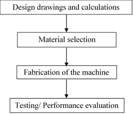
Figure 1. Flow chart of the methodology
Machine description and working principle
The palm nut cracking machine is made up of about five units viz: the feed-in unit called the hopper; the cracking unit called the drum; the driving unit consisting of an electric motor, pulley and V-belt; the driven unit which consists of a rotating shaft that bears the cracking hammers’ being driven by a V-belt connected to a prime mover.
The stand and the supporting frame is made of angle iron of gauge 50 mm by 50 mm by 6 mm. The hopper is made of mild steel of 3 mm thickness and has a capacity of 0.018 m3; and can accommodate palm nuts of about 10.8 kg at its full capacity. The cracking drum is made of mild steel of 10 mm thick, the rotating shaft is supported at both ends on bearings and it is of length 300 mm with a diameter of 25 mm for a length of 50 mm from one end and 25 mm diameter for a length of 100 mm from the other end with 30 mm diameter for a length of 150 mm at the centre, where the hammers are attached. The hammers are made of mild steel of 8 mm thick, 50 mm wide and 130 mm long. The electric motor of the driving unit is rated 1hp with frequency of 50 Hz, speed of 1400 rpm. The pulley has a diameter of 80 mm which is connected to a V-belt of length 480 mm, 12 mm wide and 9 mm thick. The pulley attached to the rotating shaft has a diameter of 175 mm.
When the palm nuts are fed into the hopper, they descend into the cracking chamber by gravity, aided by vibration agitated by the prime mover. The high rotating hammer impacts force on the nuts suddenly; the nuts are then thrown towards the wall of the cracking drum. The nuts also impact energy on the wall of the cracking drum. The sudden impact load of the hammer on the nuts lead to the breaking of the nuts and the shells are fragmented into smaller parts due to centrifugal action. The kernel and the fragmented shells are force driven out of the cracking chamber to the collecting bowl at the outlet.
Design consideration and material selection for production
In order to have efficient design, various design considerations were put into place. The hopper, drum, the cracking mechanism parts (hammer), shaft and frame were from mild steel. The thickness of the mild steel used for the hammer is more than that used for the hopper. This is expected to be because the cracking of the palm nuts require harder materials to crack the nuts and a designed speed of rotation for the shaft. The materials selected for the design and construction of the machine were majorly the stainless steel and the mild steel. The criteria of selecting these materials are: (i) durability of the material, (ii) strength of the material, (iii) suitability of the material for cracking operation, (iv) availability of the material and (v) the cost of the material.
Cracking requirement
Kinetic energy of kernels are impact energy of kernels on the cracking wall, Eq. [1]:
![]() (1)
(1)
Where: m - mass and v – velocity.
Impact energy on the cracking wall represents work required to deform a kernel, Eq. [2]:
![]() (2)
(2)
Where: F - the force or load applied and x - the distance travelled.
Impact loads applied on the kernel, Eq. [3]:
![]() (3)
(3)
Where: P - the impact loads applied to kernels and r - the ratio of the stress under impact to the direct stress or the deformation under impact to the corresponding deformation.
The ratio of stress under impact to the direct stress or the deformation under impact to the corresponding deformation is given by Eq. [4]:
![]() (4)
(4)
Where: ![]() and
and ![]()
Therefore r = 2, and F = 2P
Deformation energy can be obtained using Eq. [5]:
Hence, ![]() (5)
(5)
Where: Pe - the deformation energy and is given as 0.9012 dura nuts.
Shaft requirement
Radius of gyration of hammer, Eq. [6]:
![]() (6)
(6)
Where: h - the total height of the hammer.
To allow a gap of only 0.03 mm between the hammer and the drum, a total hammer height of 0.32 m is required.
Moment of inertia about x-axis is obtainable using Eqs. [7-8]:
![]() (7)
(7)
![]() (8)
(8)
Where: m - the mass, k - the radius of gyration, Ixx - the moment of inertia about x - axis, b and h - the width and height of the hammer, respectively.
Eqs. [9-11] illustrate the tangential force to be the tangential force
![]() (9)
(9)
![]() (10)
(10)
![]() (11)
(11)
The torque is obtained using Eq. [12]
![]() (12)
(12)
Where: ω - angular velocity and a - angular acceleration.
Mechanical power requirement
The minimum power requirement, Eq. [13]:
![]() (13)
(13)
Therefore, an electric motor of one horse power (1hp), with speed of 1400 rpm and power rating of 750 W was chosen.
Power transmitted, Eq. [14]:
![]() (14)
(14)
Where: P - power, N - speed in rpm and T - Torque produced by electric motor, T = 5.12 Nm
Density of mild steel is 7850 kg/m3, and Eq. [15] is applied to calculate the mass of the hammer:
![]() (15)
(15)
Eq. [16] was employed to determine the volume:
![]() (16)
(16)
Using the above formula, the mass of a single hammer was calculated to be 0.628 kg and the weight was derived to be 6.16 N. However, three (3) hammers were acting at a point; therefore, the point load was determined to be 18.48 N.
Design for belts
The centripetal tension of the belt was deduced using Eq. [17]:
![]() (17)
(17)
Where:
![]() - centripetal tension,
- centripetal tension, ![]() - mass and
- mass and ![]() - the speed.
- the speed.
Mass per unit length of belt, m = 0.3 kg/m; Belt Length = 48 cm = 0.48 m; Belt Breadth = 0.012 m; Belt thickness = 9 x 10³ m. Assume maximum stress in belt is 1200 kN/m2, and tension in slack side is 40% of tension in tight side.
The velocity can be derived from Eq. [18]:
![]() (18)
(18)
Angular velocity can be obtained using Eq. [19]:
![]() (19)
(19)
Where: ![]() -
angular velocity and N - speed of rotation in revolution per minute.
-
angular velocity and N - speed of rotation in revolution per minute.
Note that the ratio of the driving pulley speed to driven pulley speed is the same as the ratio of the driven diameter to the driving diameter as shown in Eq. [20].
![]() (20)
(20)
Where: N1
- r.p.m of driving pulley; N2 - r.p.m of driven pulley; d1
- diameter of driving pulley; d2 - diameter of driven pulley. From
calculation, ![]() ,
,
![]() and
and ![]() .
.
Power transmitted by the belt
This is calculated using Eq. [21]:
![]() (21)
(21)
Where: P - power
transmitted by the belt, T1 - tight side tension, T2 -
slack side tension and ![]() - the velocity. Utilizing Eq. [22], the angle of lap was
obtained:
- the velocity. Utilizing Eq. [22], the angle of lap was
obtained:
![]() (22)
(22)
Where: D - driven diameter (d1), d - driving diameter (d2), C - centre distance between the two diameters and θ - angle of lap.
Performance evaluation of the machine
Utilizing Eq. [23], the throughput capacity of the machine can be deduced Eq. [24]:
![]() (23)
(23)
or
![]() (24)
(24)
The cracking efficiency
By utilising Gbabo et al. (2013) equation for efficiency which was adopted for the dehulling efficiency for the Moringa dehulling machine by Ikubanni et al. (2017), the cracking efficiency for the palm nut cracker was derived using Eq. [25].
![]() (25)
(25)
Machine parts and fabrication
The Hopper
The hopper is the feed-in unit of the machine. It has the shape of a hollow frustum, and is made of mild steel. It has a height of 300 mm, a length of 30 mm at the bottom and 300 mm at the top of two of its plates. The other two plates have a length of 140 mm at the bottom and 300 mm at the top. The four plates are marked and cut out from a metal sheet of 3 mm thick, welded together using electric arc welding. The hopper is placed vertically on a drum to allow the nuts fall under gravity.
The Drum
The drum is the cracking unit of the machine made of mild steel plate. It is made in the shape of a hollow cylinder with a diameter of 415 mm, has a height of 200 mm, and the plates are 10 mm thick. The cylinder is covered on both sides with a circular plate 420 mm diameter which has circular openings of 50 mm diameter for shafts to pass through. Inside the drum is a portion of the shaft to which the hammers are attached. The rotating action of the hammers, as a result of the rotation of the shaft, cracks the palm nuts fed into the chamber. At the top of the drum is an opening 30 mm by 140 mm which opens up to the hopper. At the bottom also are series of openings through which cracked nuts fall out of the drum.
The Driven Unit
The driven unit consist of the shaft to which six hammers are attached and a pulley. The pulley has a diameter of 175 mm. the shaft is made of mild steel, and has a diameter of 25 mm for a length of 50 mm at one end of the shaft, a diameter of 39 mm for a length of 150 mm (to which the hammers are attached) at the centre, and a diameter of 25 mm at the other end of the shaft for a length of 100 mm.
The Hammers
The hammers are made of mild steel plates of 50 mm width, 130 mm long and 8 mm thick. Each hammer has two sections; one which is attached permanently to the shaft, and another attached to the initial plate by a temporary joint. The section attached to shaft has a length of 60 mm and is slotted at its centre to allow total change in length of the hammer. The section is 100 mm long, and is drilled 15 mm from the bottom to allow screws pass through (the same screws pass through the slot available on the first section). The change in length is required in case of wear of the tip of the hammer as a result of hitting the nuts at very high speed. The hammers are placed in pairs horizontally along the length of the shaft and an angle of 1200 separating the shafts on the circumference of the shaft.
The Driving Unit
The driving unit consist of an electric motor and a pulley. The electric motor is rated one horse power (1hp), with frequency of 50 Hz and revolves at 1400 rpm. The pulley is of diameter of 80 mm connected to the driven pulley by a belt 480 mm long, 12 mm wide and 9 mm thick.
The orthographic projection of the machine is as shown in Figure 2.
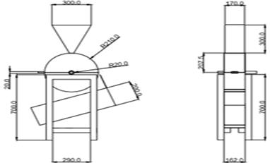
Figure 2. Orthographic projection of the machine
The isometric view of the machine indicating some of the parts is as shown in Figure 3.
|
|
|
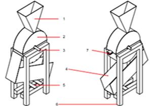
Figure 3. Isometric view of the machine
Figures 4 and 5 show the pictorial view of the machine when the cracking unit was covered and when the cracking unit was opened, respectively.
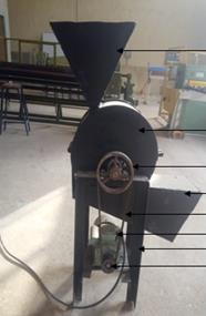
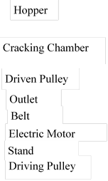
Figure 4. Pictorial view of the machine showing external parts
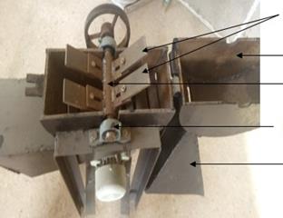
Figure 5. Pictorial view showing the cracking hammer
The cracking unit contains the rotating shaft, cracking hammers, bearing and so on.
Results and discussion
Table 1 shows the performance evaluation results for the developed palm kernel nuts cracking machine, with speed of 1400 rpm. The experimental tests show that at the same speed, 1 kg of palm kernel nut will crack at an average time of 47.58 seconds. The average mass for the un-cracked palm nuts, cracked palm nuts and partially cracked palm nuts were 0.21 kg, 0.742 kg and 0.048 kg, respectively.
Table 1. Performance tests on the developed palm kernel nuts cracking machine at 1400 rpm
|
Mass of palm kernel nuts (kg) |
Cracking time (s) |
Mass of Un-cracked nuts (kg) |
Mass of cracked nuts (kg) |
Mass of partially cracked nuts (kg) |
|
1 |
46.13 |
0.3 |
0.64 |
0.06 |
|
1 |
50.02 |
0.2 |
0.76 |
0.04 |
|
1 |
48.26 |
0.27 |
0.66 |
0.07 |
|
1 |
44.21 |
0.18 |
0.8 |
0.02 |
|
1 |
49.27 |
0.1 |
0.85 |
0.05 |
|
Average |
47.58 |
0.21 |
0.742 |
0.048 |
As observed from Table 1, the experiments carried out in evaluating the machine show that 1kg of palm kernel nut cracks at an average time of 47.58 seconds. This implies that in 1 second, the machine will crack 0.021 kg of palm kernel, that is, 0.021 kg/s or 21 g/s.
This is the estimated throughput value of the machine as shown in Table 2. The hopper has the shape of a frustum of a pyramid. The total mass of the palm nuts that can be accommodated in the hopper is 10.8 kg. Since 1 kg of palm nut takes 47.58 sec, therefore 10.8 kg will take 514 secs which is about 9 mins. Based on the average amount of cracked palm nuts obtained after the cracking operation from the supplied palm nuts into the machine, it can be said that the average efficiency of the machine is about 74.2 %. The palm kernel nut cracking machine has an average efficiency of about 74.2 %.
The efficiency of the machine which is not too high might be due to so many factors. This could include error in design and fabrication when there is no precision welding. It can be stated that the size of the nuts has little or no effect on the efficiency of the cracking machine developed. The average amount of palm nuts cracked per day by the cracking machine is about 1872 kg. This will take an average farmer about 144 kg per day to achieve this.
Table 2. Cracking time and throughput of the palm nut cracking machine at 1400 rpm
|
Mass of palm kernel nuts (g) |
Cracking time (s) |
Throughput (g/s) |
|
1000 |
46.13 |
21.678 |
|
1000 |
50.02 |
19.992 |
|
1000 |
48.26 |
20.721 |
|
1000 |
44.21 |
22.619 |
|
1000 |
49.27 |
20.296 |
|
Average |
47.58 |
21.061 |
As illustrated in Table 2, it can be deduced that the lower the cracking time at constant speed of 1400 rpm, the higher the throughput of the machine. Tables 2 – 4 show the obtained values of cracking time and throughput capacity of the machine at three different shaft speeds.
Table 3. Cracking time and throughput of the palm nut cracking machine at 1200 rpm
|
Mass of palm kernel nuts (g) |
Cracking time (s) |
Throughput (g/s) |
|
1000 |
59.53 |
16.798 |
|
1000 |
60.03 |
16.658 |
|
1000 |
58.13 |
17.203 |
|
1000 |
59.77 |
16.73 |
|
1000 |
60.22 |
16.606 |
|
Average |
59.54 |
16.799 |
As shown in Table 3, the average cracking time and throughput value at 1200 rpm shaft speed are 59.54 s and 16.799 g/s, respectively. Cracking time is a determinant in obtaining higher or lower through put which also depend largely on the speed of rotation of the shaft carrying the hammer.
Table 4. Cracking time and throughput of the palm nut cracking machine at 800 rpm
|
Mass of palm kernel Nuts (g) |
Cracking time (s) |
Throughput (g/s) |
|
1000 |
86.52 |
11.558 |
|
1000 |
85.23 |
11.733 |
|
1000 |
85.47 |
11.7 |
|
1000 |
87.11 |
11.479 |
|
1000 |
86.49 |
11.562 |
|
Average |
86.14 |
11.606 |
The average cracking time and throughput value at 800 rpm shaft speed are 86.14 s and 11.606 g/s, respectively as shown in Table 4.
The average cracking time and throughput of the machine at different shaft speed was obtained as shown in Table 5.
Table 5. Average cracking time and throughput of the machine at different shaft speed
|
Shaft Speed (rpm) |
Average Cracking time (s) |
Throughput (g/s) |
|
800 |
86.14 |
11.606 |
|
1200 |
59.54 |
16.799 |
|
1400 |
47.58 |
21.061 |
It was observed that the cracking time reduces as the shaft speed increases and the throughput increases as shaft speed increases. This agrees with the work of Udo et al. (2015) that as the shaft speed increases, the cracking time declines while there is increase in throughput. This implies that the lower the shaft speed, the higher the cracking time and the lower the throughput of the machine.
Conclusions
A palm nut cracking machine with an efficiency of 74.2 %, a throughput capacity of 75.6 kg/hr has been successfully and economically designed and developed. The machine was developed using locally sourced materials. Also, maximum loading of the hopper which is about 10.8 kg and 0.02 m3 in volume will be cracked in about 9 minutes. The average amount of palm nuts cracked per day by the cracking machine is about 1872 kg. The cracking time decreases and throughput increases as the shaft speed increases. The machine is easy to operate, efficient and affordable. Therefore, the cracking machine using locally sourced materials will help increase productivity and efficiency in the palm nut cracking process in the rural areas.
Acknowledgements
The authors wished to appreciate the effort of the technicians in the Mechanical workshop of Landmark University for the assistance during the fabrication of the machine.
References
1. Okokon F., Okoko P., Akanga A., Umani K., Obot N., Effect of rotor speeds of centrifugal palm nut cracker on the characteristics of the constituents of the crack mixture, International Journal of Agricultural Policy and Research, 2015, p. 324-327.
2. Ismail S., Ojolo S., Orisaleye J., Adediran A., Fajuyitan O., Design and development of an improved palm kernel shelling and sorting machine, European International Journal of Science and Technology, 2015, p. 225-240.
3. Udo S., Adisa A., Ismail S., Adejuyigbe S., Development of palm nut cracking machine for rural use, Agric Eng Int: CIGR Journal Open access, 2015, p. 389-406.
4. Global Food book: Some important facts about palm kernels (accessed February 7, 2017, available from: https://globalfoodbook.com/some-important-facts-about-palm-kernels/).
5. Poku K., Small scale palm oil processing in Africa, FAO Agricultural Services Bulletin, Publishing Management Service, Information Division, Rome, 2002, 148, p. 56.
6. Oyebanji, J.A., Oyedepo S.O., Adekeye T., Performance evaluation of two palm kernel nut cracker machines, Proceeding of ICCEM, 2012, p. 211-223.
7. Oke P.K., Development and performance evaluation of indigenous palm kernel dual processing machine, Journal of Engineering and Applied Sciences, 2007, 2 (4), p. 701-705.
8. Adejuyigbe I.T., Oyegunwa O.A., Iliya A.A., Aigbogun J.O., Oyelami A.T., Olusunle S.O.O., Design and development of an improved palm kernel shelling machine and separator, Physical Science International Journal, 2017, 14 (3), p. 1-9.
9. Asibeluo I.S., Abu A.L., Design and construction of a palm kernel cracker and separator, International Journal of Engineering Trends and Technology, 2015, 20 (3), p. 159-165.
10. Koya O., Palm nut cracking under repeated load, Journal of Applied Sciences, 2006, 6 (11), p. 2471-2475.
11. Jimoh M.O., Olukunle O.J., Design of an effective automated machine for quality palm kernel production, IOSR Journal of Mechanical and Civil Engineering, 2013, 6 (1), p. 89-97.
12. Gbabo A., Liberty J.T., Fadele O.S., Design, construction and assessment of African locust bean (Parkia biglobosa) dehuller and separator, International Journal of Engineering and Innovative Technology, 2013, 3 (5), p. 438-444.
13. Ikubanni P.P., Komolafe C.A., Agboola O.O., Osueke C.O., Moringa seed dehulling machine: A new conceptual design, Journal of Production Engineering, 2017, 20 (2), p. 73-78.